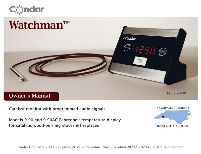
CGX AIM User manual

Description
The AIM Physiological Monitor provides
pulse oximetry (PPG), heart-rate
variability (HRV), oxygen saturation
(SpO2), respiration, temperature,
galvanic skin response (GSR), and
four EXG channels in a portable, self-
contained, wireless system.
Wireless technology allows the subject
to move about while real-time data is
collected and displayed.
The device uses a modular design; any
AIM Physiological Monitor
CGX A Cognionics Company
Note
• This is an investigational device designed for research and development eorts.
• It is not an FDA-approved medical device.
• There are no known side eects from the use of this product.
This manual contains general operating instructions, precautionary measures,
maintenance instructions, and information for use of the CGX AIM Physiological
Monitor. Please read this manual carefully and familiarize yourself with the
controls and accessories before using the product.
combination of sensors can be used at
any time, from a single sensor to every
sensor simultaneously.
Sensor channels are sampled at a time
resolution of 500Hz and converted to
digital data at 24 bits of resolution.
The AIM Physiological Monitor provides
research-grade signal quality and is
ideally suited for laboratory and field
environments.

Page 2
Warnings
TheAIMisintendedtobeusedto
acquirebiometricsignalsandtransmit
themwirelesslytoacomputer.
ThisDeviceIsIntendedForResearch
Only.
ItIsNotIntendedForTheFollowing
Uses:
• monitoring of patients in a clinical
environment
• use in medical diagnosis
• on subjects undergoing surgery
• use in sterile environments
• use with sleeping subjects
DoNotUseThisProductInThese
Situations:
• near high-frequency surgical equipment
• if exposed to ionizing radiation
• in oxygen-rich environments
(concentration > 25% at 1 atm)
• in wet environments
• in the presence of ammable anesthetics
or gases
PrecautionsForThePractitioner
• Do not drop, sit on, or step on the
product.
• Check if your subject has a sensitive
dermatological condition causing sensor
intolerance.
• To avoid cross-subject contamination,
do not use with subjects having open
wounds or infections.
• The AIM is not a diagnostic tool.
Any medical diagnosis related to the
measurements should be derived by a
certied physician.
SubjectConsiderations
• This device is intended for human use
only.
• Subject should have healthy skin.
• Do not use with infants or neonates.
FollowTheseAdvisoriesToKeepYour
AIMInGoodWorkingOrder
• Do not immerse any part of the system in
liquid.
• Do not expose the system to direct
sunlight or heat source, moisture,
vibration, mechanical shock, excessive
dust, or humidity.
• Do not open, modify or disassemble any
part of the system — this will void the
warranty.
• Do not use if any part of the system is
damaged.
• Do not use when wet — if moisture
penetrates the system, let it thoroughly
dry prior to use.
• Do not use caustic or abrasive cleaners
on the system or sensors.
• Avoid sharply bending the lead wires.
DisposableSensorsMayBeA
Biohazard
Dispose of EXG sensors after each use.
AlwaysUseSuppliedAccessories
Using accessories other than those
supplied with your system may result
in damage or diminished ecacy of the
system.
AvoidCross-SubjectContamination
Clean the device and clean or replace
sensors after use following the cleaning
instructions on Page 10 to avoid cross-
subject contamination.

Page 3
PackageContents
ThePackageContainsThe
FollowingItems
AIM Wireless Amplier
Bluetooth Dongle
11 Passive Lead Wires
PPG/HRV/SpO2 Sensor
Temperature Sensor
Respiration Sensor Set
30 Skintact ECG Electrodes
USB Charging Cable
Wall Charger
Carrying Case
Manual
4 EXG Ports
GND
Respiration
SpO2
Temperature
GSR
AIMPhysiologicalMonitor
Micro USB
Charging Port
Battery LED
Power LED
Trigger LED
Power Button

DeviceOverview
AIM
Wireless amplifier
collects signals and
transmits to Bluetooth
Dongle.
BlutoothDongle
High-speed receiver
dongle plugs into your
computer’s USB port.
PassiveLeadWires
Passive lead wire for
ExG, GSR and GND
PPG/HRV/SpO2 Temperature SkinTactElectrodesRespiration
Combined pulse
oximeter (PPG)/heart-
rate variability (HRV)/
oxygen saturation
(SpO2) sensor
provided in a clip form-
factor for application
on the earlobe or
fingertip.
Respiration paddles
applied just below the
collarbones provide
respiration data and
ECG.
Place the temperature
sensor anywhere on
the body to record
surface temperature.
Sticky electrodes for
use with ExG sensors,
GSR sensors, and
Respiration paddles

Page 5
SensorSetupGuide
You can use any combination of sensors concurrently.
PPG/SpO2/HRSensor
To acquire PPG/SpO2/HR, connect the PPG/SpO2/HR
module to the 9-pin port on the top left side of the amplier.
You do not need to attach a ground terminal (GND).
• Clip PPG/SpO2/HR sensor onto the ngertip or earlobe.
• Go to the Display tab in the software and change the
channels from All to 1
• Set the Show Page drop-down menu to EEG7to7.
• View SpO2 and heart rate data on the Status tab in the
software.
• Heart rate is listed in beats per minute.
• SpO2 is listed as a percentage of blood oxygen
saturation.
RespirationSensorPaddles&ECGMeasurements
To acquire respiration and ECG signals:
1. Attach the two respiration paddles to the positive and
negative respiration inputs on the AIM device.
2. Attach a lead to the ground terminal (GND).
3. Snap Skintact electrodes into the respiration and
ground sensors.
4. Attach ground.
5. Apply respiration paddles to the subject so arrows
on the paddles face each other and point toward the
midline. Paddles should sit just below the collarbone.
6. To view both the ECG and respiration signals in the
software, go to the Display tab in the software and
change the channels from All to 2
7. Set the Show Page drop-down menu to EEG5to6
TemperatureSensor
To acquire temperature:
1. Connect the temperature module to the AIM. You do
not need to attach a lead to the ground terminal (GND).
2. Hold the temperature sensor in the hand or tape under
the arm for increased accuracy.
3. View temperature data (Celsius) on the Status tab in
the software.
SensorOverview
PPG/SpO2/HRSensor
RespirationPaddles
TemperatureSensor

Page 6
SensorOverview
GSRSensor
To acquire a GSR signal:
1. Connect passive lead wires into the positive and
negative GSR ports.
2. Attach a lead to the ground terminal (GND).
3. Snap Skintact electrodes into the GSR and ground
sensors.
4. Attach ground and GSR sensors to the body.
5. To display the GSR channel, go to the Display tab in
the software and change the channels from All to 1.
6. Set the Show Page drop-down menu to EEG10to10
EXGSensors
1. Attach passive lead wires to the positive and the
negative ExG channel inputs for however many ExG
channels you want to acquire.
2. Attach a lead to the ground terminal (GND).
3. Snap Skintact electrodes into each sensor.
4. Place the leads and ground onto the subject on the
desired locations.
5. To selectively display ExG channels, go to the Display
tab in the software and change the channels from All
to 1.
6. Navigate between the ExG channels by using the Show
Page drop-down menu.
EXGSensors
Use passive lead wire and
Skintact electrode.
GSRSensor
Use passive lead wire and
Skintact electrode.

Page 7
CommonConfigurations
EmotionalArousal/StressTest
Measure emotional arousal in response to presented
stimulus, capturing changes in respiration, heart rate, and
galvanic skin response.
• Respiration paddles.
• GSR sensors placed close together on the palm of the
hand.
CardiacOutputTest
Measure common cardiac functions for monitoring heart
health including blood oxygen saturation, heart rate
variability, and respiratory sinus arrhythmia.
• SpO2 on ear.
• Respiration paddles.
ECG+EMG+RespirationTest
Measure physiological response in a light ambulatory
setting, capturing muscle EMG from the leg.
• Respiration paddles.
• ECG electrodes across the heart on the left upper chest
with the medial sensor placed above the heart and the
lateral sensor below.
• EMG electrodes to the upper quadricep with one sensor
placed above the other.
EmotionalArousal/Stress
CardiacOutput
ECG+EMG+Respiration

Page 8
ProductFeatures
PowerButton
Push button to turn the device on and o.
MicroUSBPort
Use the Micro USB port to charge the AIM Physiological
Monitor.
TriggerLED
The Trigger Status Light is for use with the optional CGX
Wireless StimTrigger, and indicates when the headset is
receiving trigger signals from the StimTrigger unit.
Off Wireless StimTrigger Out Of Range
Blue Wireless StimTrigger In Range
BatteryLED
The bottom light is the battery indicator.
• Red indicates charge is not complete.
• Green indicates full charge.
Note: Fully charge the battery before use.
BeltClip
The back face holds the optional belt clip for ambulatory
signal capture.
PowerLED
GreenOn
YellowLow Battery
RedBattery Critically Low
TriggerLED
OffOut Of Range
BlueIn Range
Power
Indicator
Trigger
Indicator
Battery LED
Belt Clip
Micro
USB Port

Page 9
USBDongle
Plug the dongle into your computer and Windows should
automatically install the correct drivers. Verify driver
installation by checking the Device Manager for problems,
marked by a yellow exclamation mark.
• The dongle is specic to each headset.
• For best performance, ensure a clear line of sight between
the dongle and the front of the headset
If Windows did not successfully install the driver for
the dongle, refer to the FTDI driver installation manual
on our website.
Each AIM is permanently paired to a receiver dongle. The
pair automatically discover and initiate a connection when
both are powered on and within a 10m range.
The light on the dongle indicates its current state:
Green Power On, Not Paired
Purple Searching For Device
Blue Device Found
FlashingBlue Data Transmitting
Preparation
AIMDongle
Green Not paired
Purple Searching for device
Blue Device found
FlashingBlue Data
transmission
StarttheAcquisitionSoftware
Have the CGX Data Acquisition software installed and
ready.
Insert the AIM Physiological Monitor’s Bluetooth dongle
into your computer’s USB port. If you are using a desktop
computer, insert the dongle into a port facing the subject
not obscured by the computer’s chassis.
Double click on the CGX Data Acquisition Software icon.
You should see CGXAIMPhys.Mon. under Discovered
Devices. If you do not, remove and re-insert the dongle,
then restart the software.
Click the device name in this window to select the AIMand
click Connect.
You should see a small pop-up window asking if you wish
to auto-congure. Click Yes. If you do not see the pop-up,
check beneath the main window of the software.
You should now see the device conguration window
momentarily. If you do not, double check to make sure the
AIM is powered on and in standalone mode.
Keep settings in their default values. Click WritetoDevice
andStart
You will now see data streaming into the display.
AcquisitionSoftware
Download the latest copy here:
http://cognionics.com/
wiki/pmwiki.php/Main/
DataAcquisitionSoftware

Page 10
RecordingASession
After you have an acceptable connection on all applicable
sensor channels, go to:
• Device>Recordto begin recording.
• To end recording, click StopRecordingunder the same
tab.
EndingASession
• Close out the current le in the software if one is active
and exit the program.
• Press the power button once to turn o the device.
• Disconnect all leads from the system before storing.
RecordingASession
To avoid cross-subject contamination, follow the cleaning
instructions to clean sensors and system after each use.
This device is not intended to be sterilized in an autoclave.
CleaningSensors
Use hand sanitizer or 70% alcohol wipes to clean
components that contact the skin.
BatteryStorage
Remove the batteries when system is not in use.
DisposalInstructions
To protect the environment, always follow local law, rules,
and policies regarding electronic and battery disposal. You
may also return the system to CGX for proper disposal.
Use the supplied carrying case when transporting the
system to avoid damage to the amplier or any of the
components.
CareAndHandling
PositionOfTheSubject
DuringRecording
Use the AIM Physiological
Monitor for subjects in an
upright position or for low-
impact ambulatory recordings.
Do not let the subject lie or
sleep on the sensors.

Page 11
ResettingtheAmplifier
Resetting the amplier will set the device back to its original
settings and can resolve a wide range of issues.
If the AIM Physiological Monitor has been miscongured
or is otherwise unable to contact the software, reset the
amplier by turning the device on and o.
Since the AIM’s settings are stored in the device, this reset
process can cause issues if you have changed the auto-
conguration screen to t your experiment. Please contact
CGX support if you have changed your settings and need to
reset your device.
PowerIssues
If the AIM Physiological Monitor does not power on OR
powers on but quickly shuts o, check to make sure the
battery is fully charged.
OtherIssues
If you nd still have issues or questions, please contact us
Troubleshooting

Page 12
The most important aspect of AIM recording is that
output data is only as good as the recording input. While
algorithms exist to remove artifacts, poorly recorded data
cannot be xed in post processing.
Recording good data requires preparation of the participant
for optimal sensor contact:
1. Clean each sensor location on the subject with a cotton
swab soaked with 70% alcohol.
2. It is important for subjects to reduce tension in the
head, neck, and shoulders during readings.
UnderstandingReadings
Using the EXG leads without
ground will cause the channel
to be obscured by electrical
(50/60Hz) noise.
MissingGround
TroubleshootingReadings
EXGMissingALead
Using a single EXG lead
will cause the signal to be
obscured by electrical noise.

Page 13
UnderstandingReadingsUnderstandingReadings
GSRMissingGround
GSRMissingALead
Using the GSR leads without
ground will display a sinusoidal
artifact and the module will not
show functional data.
Using the GSR with only a
single lead will cause a at
line.

Page 14
UnderstandingReadings
RespirationPaddlesTooCloseTogether
Respiration paddles placed
too close to each other display
poor signal quality. Amplitude
of respiration and ECG
channels will be lower than
expected.
Only1RespirationPaddleConnected
Without using both respiration
paddles, the respiration signal
presents as noise and the ECG
will be unreliable and noisy.
RespirationPaddlesPlacedProperly
When the respiration paddles
are placed properly the
ECG channel will display
a distinct and clean signal
and the respiration paddle
will be responsive to actual
respiration.

Page 15
RunningTheAcquisitionSoftware
DeviceConfiguration
• DiscoveredDevicesConnected dongles will be listed
here. Select the device name of your system and hit
Connect.
• The software automatically connects to your device to
retrieve stored settings.
• The DeviceConfigurationwindow is only for your
information; changing the settings will not change the
conguration of the device. If you need to change device
conguration, contact support at CGX.
DataRecording
• Record Click to open a le dialog. Select the desired
location, le name, and le type. (CSV les have a time
stamp built in). Recording begins when you press OK.
• ToStopRecordinghit the button again. Elapsed time is
shown in the box above the button.
• StartLabStreamingLayerHit the Start
LabStreamingLayerbutton.
• StartRDAServer To use the BCI2000 software with the
Data Acquisition Software, click on this button. Then,
connect to the application in BCI2000.
• Timer The timer allows you to limit le recording to a
specic length.
DeviceTab

Page 16
RunningTheAcquisitionSoftware
DisplayTab
The display tab controls
scaling and other viewing
parameters for the signals.
Scaling:Headset
• Time sets the x axis time window. By default, it is set to 2
seconds.
• Scale(EEG) sets the y axis vertical gain for the EEG
channels on the head.
• Scale(ACC) sets the y axis vertical gain for the
accelerometer channels.
• Channels sets the maximum number of channels
displayed per screen. To ip through the pages of
channels, use the option below.
• ShowPage switches between dierent pages of
channels.
Scaling:AIMPhysiologicalMonitor
Filtering
• HighPass sets the oor (removes osets and slow
signals) corner frequency for the display.
• Lowpass sets a ceiling (removes high frequency signals
and noise) corner frequency for the display.
• Note: ltering is for display only. Data les are saved
raw and unltered to preserve the maximum amount of
information.
MaskHi-ZChannels
Threshold hides channels with sensor impedances above
the specied threshold from the display.

Pa ge 17
RunningTheAcquisitionSoftware
The top half of the Channels
tab contains a table
displaying information about
each channel in the system
including its number, name,
contact impedance (Z (kΩ))
and sensor oset (O (mV)).
The oset is calculated
relative to the reference
channel A1.
ChannelsTab
The bottom half is a graphical map of sensor contact
quality. Red circles indicate poor contact, whereas light
green circles indicate acceptable contact. Dark green
circles indicate ideal contact.
The threshold for this contact quality is, by default:
Red Above 5000 kΩ
LightGreen Between 2500-5000 kΩ
DarkGreen Below 2500 kΩ
This threshold can be changed with the Mask Hi-Z menu
on the display tab.
Red 100% or greater of Hi-Z threshold
LightGreen Between 50%-100% of Hi-Z threshold
DarkGreen Below 50% of Hi-Z threshold

Page 18
RunningTheAcquisitionSoftware
MarkersTab
ReceivedTriggers
• The box shows all of the received triggers chronologically.
• If no trigger is in range, value received will be 47831 (in
hex: 0xBAD7).
• ClearHistoryThis button will clear all of the triggers in the
box. It will not delete triggers from the recording itself.
InsertManualTriggers
• You have the option to select any one of eight trigger
codes to insert into the recording. These will be inserted
in the same way as a normal trigger sent from our
Wireless StimTracker. However, we recommend only
using the trigger for precision event marking, and to use
these software triggers for general annotation.
TCPTriggers
• PortNumber Allows you to choose which port to receive
triggers.
• StartTCPReceiver Starts the receiving service.
• Do not use for precision event marking.
• For general annotation only.

WirelessAmplier
A/DResolution 24-Bit simultaneous sampling
analog-to-digital converters
SamplingRate 500 samples per second
Bandwidth 0-131 Hz with true DC coupling
Accelerometer 3-axis, measures head motion
WirelessRange 10 meters
Noise <1.0 μV RMS from 1-30 Hz,
shorted inputs
Sensors
Included
Sensors
PPG/SpO2/HR
Bioimpedance-based Respiration
12-bit solid state Temperature
GSR (EDA)
4 Channels ExG
Specifications
DataStream
Streaming
Stream data using the simple API
in C, C++, C#, Java, MATLAB or
Python.
ExportDataTo EEG or CSV (text)
API Open API to build custom
applications.
Power
Power Rechargeable Lithium-Ion battery
SupplyVoltage 3.7 V DC
Power
Consumption 0.4 VA , 5 hour battery life
General
Weight 190g
Dimensions
(LWH) 14 x 8 x 3 cm

Device
3 year warranty on manufacturing defects. 90 day warranty on disposable parts. All units
returned to CGX for repair and assessment must have an RA number, issued by CGX. CGX
will pay outbound shipping costs only.
Returns
Ship all returns with an RA number to:
CGX
Attn: Service
8445 Camino Santa Fe, #104
San Diego, CA 92121
WarrantyandService
CoveredbyPatentsissuedand/orpendingunderlicensefromCognionics,IncUS9314183B2,
US9615761B2, US9935726B2, US8798710B2, and International patents. © 2020 CGX, LLC. Doc: AIMPM100120
8445 Camino Santa Fe, #104
San Diego, CA 92121
858-864-9400
CGX A Cognionics Company
Imported By:
Brain Products GmbH
Zeppelinstrasse 7
82205 Gilching, Germany
www.brainproducts.com
Table of contents
