CH Hanson Palmgren Powergrind-XP 9682072A User manual

9682072A, 9682073A & 9682075A
Bench Grinders
Read carefully and follow all safety rules and operating
instructions before first use of this product.
9643556.01-1018
Operating Manual & Parts List
9682073A shown.

2
Palmgren Operating Manual & Parts List 9682072A, 9682073A and 9682075A
DESCRIPTION
Palmgren Bench Grinders are equipped with a totally enclosed ball
bearing motor. Armature assembly is dynamically balanced for
smooth operation. Motor housing is compact so long pieces of
work can press against both wheels without touching the motor
frame. Removable wheel guards allow for easy changing of wheels.
Two-way tool rests are adjustable for wheel wear and angle grind-
ing. Grinders come complete with spark guards, safety eyeshields
and dust collection hose. .
UNPACKING
Check for shipping damage. If damage has occurred, a claim must
be filed with the carrier immediately. Check for completeness. Im-
mediately report missing parts to dealer.
To be certain the grinding wheels have not been damaged in ship-
ment, strike the edges slightly with a metal object. A ringing sound
indicates a good wheel, but a dull noise may signal a fracture.
WARNING: If you suspect a wheel of being fractured, replace it
immediately. Fractured wheels may shatter, causing serious injury.
SPECIFICATIONS
9682072A, 6” Bench Grinder
Horsepower . . . . . . . . . . . . . . . . . . . . . . . . . . . . . . . . . . . . . . . . . . . . . . . . . . 1/2
Voltage . . . . . . . . . . . . . . . . . . . . . . . . . . . . . . . . . . . . . . . . . . . . . . . . . . 115/230
Amperes . . . . . . . . . . . . . . . . . . . . . . . . . . . . . . . . . . . . . . . . . . . . . . . . . . 5.5/2.8
Hertz . . . . . . . . . . . . . . . . . . . . . . . . . . . . . . . . . . . . . . . . . . . . . . . . . . . . . . . . . . 60
Phase . . . . . . . . . . . . . . . . . . . . . . . . . . . . . . . . . . . . . . . . . . . . . . . . . . . . . . Single
RPM . . . . . . . . . . . . . . . . . . . . . . . . . . . . . . . . . . . . . . . . . . . . . . . . . . . . . . . . 3600
Rotation (viewed from left side) . . . . . . . . . . . . . . . . . . . . . . . . Clockwise
Wheel diameter . . . . . . . . . . . . . . . . . . . . . . . . . . . . . . . . . . . . . . . . . . . . . . . . 6”
Wheel bore . . . . . . . . . . . . . . . . . . . . . . . . . . . . . . . . . . . . . . . . . . . . . . . . . . 1/2”
9682073A, 8” Bench Grinder
Horsepower . . . . . . . . . . . . . . . . . . . . . . . . . . . . . . . . . . . . . . . . . . . . . . . . . . . . 1
Voltage . . . . . . . . . . . . . . . . . . . . . . . . . . . . . . . . . . . . . . . . . . . . . . . . . . 115/230
Amperes . . . . . . . . . . . . . . . . . . . . . . . . . . . . . . . . . . . . . . . . . . . . . . . . . . . . 10/5
Hertz . . . . . . . . . . . . . . . . . . . . . . . . . . . . . . . . . . . . . . . . . . . . . . . . . . . . . . . . . . 60
Phase . . . . . . . . . . . . . . . . . . . . . . . . . . . . . . . . . . . . . . . . . . . . . . . . . . . . . . Single
RPM . . . . . . . . . . . . . . . . . . . . . . . . . . . . . . . . . . . . . . . . . . . . . . . . . . . . . . . . 3600
Rotation (viewed from left side) . . . . . . . . . . . . . . . . . . . . . . . . Clockwise
Wheel diameter . . . . . . . . . . . . . . . . . . . . . . . . . . . . . . . . . . . . . . . . . . . . . . . . 8”
Wheel bore . . . . . . . . . . . . . . . . . . . . . . . . . . . . . . . . . . . . . . . . . . . . . . . . . . 5/8”
9682075A, 10” Bench Grinder
Horsepower . . . . . . . . . . . . . . . . . . . . . . . . . . . . . . . . . . . . . . . . . . . . . . . . . . 1½
Voltage . . . . . . . . . . . . . . . . . . . . . . . . . . . . . . . . . . . . . . . . . . . . . . . . . . 115/230
Amperes . . . . . . . . . . . . . . . . . . . . . . . . . . . . . . . . . . . . . . . . . . . . . . . . . . 15/7.5
Hertz . . . . . . . . . . . . . . . . . . . . . . . . . . . . . . . . . . . . . . . . . . . . . . . . . . . . . . . . . . 60
Phase . . . . . . . . . . . . . . . . . . . . . . . . . . . . . . . . . . . . . . . . . . . . . . . . . . . . . . Single
RPM . . . . . . . . . . . . . . . . . . . . . . . . . . . . . . . . . . . . . . . . . . . . . . . . . . . . . . . . 1800
Rotation (viewed from left side) . . . . . . . . . . . . . . . . . . . . . . . . Clockwise
Wheel diameter . . . . . . . . . . . . . . . . . . . . . . . . . . . . . . . . . . . . . . . . . . . . . . 10”
Wheel bore . . . . . . . . . . . . . . . . . . . . . . . . . . . . . . . . . . . . . . . . . . . . . . . . . . . . 1”
SAFETY RULES
WARNING: For your own safety, read operating instructions
manual before operating tool.
PROPOSITION 65 WARNING: Some dust created by using
power tools contain chemicals known to the state of California to
cause cancer, birth defects or other reproductive harm.
Some examples of these chemicals are:
• Lead from lead-based paints
• Crystalline silica from bricks and cement and other masonry
products.
• Arsenic and chromium from chemically treated lumber.
Your risk from these exposures varies, depending on how often you
do this type of work. To reduce your exposure to these chemicals;
work in a well ventilated area and work with approved safety
equipment. Always wear OSHA/NIOSH approved, properly fitting
face mask or respirator when using such tools.
BE PREPARED FOR JOB
• Wear proper apparel. Do not wear loose clothing, gloves, neck-
ties, rings, bracelets or other jewelry which may get caught in
moving parts of machine.
• Wear protective hair covering to contain long hair.
• Wear safety shoes with non-slip soles.
• Wear safety glasses complying with United States ANSI Z87.1.
Everyday glasses have only impact resistant lenses. They are
NOT safety glasses.
• Wear face mask or dust mask if operation is dusty.
• Be alert and think clearly. Never operate power tools when tired,
intoxicated or when taking medications that cause drowsiness.
PREPARE WORK AREA FOR JOB
• Keep work area clean. Cluttered work areas and work benches
invite accidents.
• Do not use power tools in dangerous environments. Do not use
power tools in damp or wet locations. Do not expose power
tools to rain.
• Work area should be properly lighted.
• Use proper extension cord. Make sure your extension cord is in
good condition. When using an extension cord, be sure to use
one heavy enough to carry the current your product will draw.
An undersized cord will cause a drop in line voltage resulting in
loss of power and overheating. Extension Cord Table on page 4
shows the correct size to use depending on cord length and
nameplate ampere rating. If in doubt, use the next heavier gage.
The smaller the gage number, the heavier the cord.
• Keep visitors at a safe distance from work area.
• Keep children out of the workplace. Make workshop childproof.
Use padlocks, master switches or remove switch keys to prevent
any unintentional use of power tools.
TOOL SHOULD BE AINTAINED
• Always unplug tool prior to inspection.
• Consult manual for specific maintaining and adjusting
procedures.
• Keep tool clean for safest operation.
• Remove adjusting tools. Form habit of checking to see that
adjusting tools are removed before turning machine on.
• Keep all parts in working order. Check to determine that the
guard or other parts will operate properly and perform their
intended function.
• Check for damaged parts. Check for alignment of moving parts,
binding of moving parts, breakage of parts, mounting and any
other condition that may affect a tool’s operation.
• A guard or other part that is damaged should be properly re-
paired or replaced. Do not perform makeshift repairs. (Use the
parts list to order replacement parts.)
• Maintain tools with care. Keep tools sharp and clean for best
and safest performance. Follow instructions for lubricating and
changing accessories.

3
Palmgren Operating Manual & Parts List 9682072A, 9682073A and 9682075A
SAFETY RULES (CONTINUED)
KNOW HOW TO USE TOOL
• Use right tool for job. Do not force tool or attachment to do a
job for which it was not designed.
• Disconnect tool from power when changing accessories such as
grinding wheels, buffing wheels and the like.
• Avoid accidental start-up. Make sure that the switch is in the off
position before plugging in.
• Do not force tool. It will work most efficiently at the rate for
which it was designed.
• Keep hands away from moving parts and grinding surfaces.
• Never leave a tool running unattended. Turn the power off and
do not leave tool until it comes to a complete stop.
• Do not overreach. Keep proper footing and balance.
• Never stand on tool. Serious injury could occur if tool is tipped
over.
• Know your tool. Learn the tool’s operation, application and
specific limitations.
• Use recommended accessories. Understand and obey all safety
instructions supplied with accessories. The use of improper
accessories may cause risk of injury to persons.
• Do not over tighten wheel nut. Replace cracked wheel
immediately. Use only flanges supplied with the grinder.
• Adjust distance between wheel and tool rest to maintain 1/16”
or less gap.
• Handle the workpiece correctly. Whenever possible, use tool
rest to support workpiece during grinding operation. Turn tool
off if it jams.
• Secure work. Use clamps or a vise to hold work when practical.
It's safer than using your hand and it frees both hands to oper-
ate tool.
• Always use guards and eyeshields.
• Clean grinding dust from beneath tool frequently.
• Direction of feed. Feed work into a blade or cutter against the
direction of rotation of the blade or cutter only.
ASSEMBLY
Parts to be fastened to the unit should be located and accounted
for before assembly.
I PORTANT: Do not attempt assembly if parts are missing. Use this
manual to order replacement parts.
A Knob (2)
B Flat washer, 5/16” (6)
C Tool rest bracket (2)
D Tool rest (2)
E Flat washer, 3/8” (2)
F Knob (2)
G Pan head screw, 3/16” x 3/8” (4)
H Upper eyeshield bracket (2)
I Eyeshield (2)
Lower eyeshield bracket (2)
K Knob (2)
L Spark Deflector (2)
M Knob (2)
TOOL REST ASSE BLY
Refer to figure 1
1. Place tool rest (D) over tool rest bracket (C) and secure in
position with knob (F) and flat washer (E).
2. Attach tool rest bracket (C) to the bottom of the wheel guard
(O) using knob (A) and flat washer (B). Make sure that the slot of
the bracket is located over the raised boss on the wheel guard.
Secure in position with knob.
3. Position tool rest (D) so that distance between tool rest (D) and
wheel (P) is less than 1/16”. Reposition angle of tool rest if
necessary. Secure all knobs.
• Mount right tool rest in a similar manner.
EYESHIELD ASSE BLY
Refer to figure 1
1. Attach spark guard (L) to left wheel guard (O) using knob (M),
spring washer (N) and flat washer (B).
2. Mount left upper eyeshield bracket (H) to eyeshield (I) and
lower eyeshield bracket ( ) using two pan head screws (G).
NOTE: Left upper eyeshield bracket is stamped “L” for identification.
3. Slide knob (K) through hole at top of left spark deflector (L) into
upper eyeshield bracket (H) and secure in position.
4. Locate eyeshield in desired position for protecting operator and
secure all knobs and bolts.
• Mount right eyeshield assembly in a similar manner.
DUST COLLECTION HOSE
• A dust collector hose has been provided with grinder. Slide
hoses onto sides of T-connector and flanges. Mount the hose by
sliding the flanges at each end over the exhaust ports on the
left and right wheel guards. Attach 2½” shop vacuum hose to
collector hose. Be sure hose is mounted securely.
DANGER: Be sure to empty shop vacuum of all flammable
material (flammable liquids and vapors, paper, wood, plastic, etc.)
before connecting vacuum to grinder. Hot sparks from grinder may
ignite flammable materials in shop vacuum.
INSTALLATION
OUNT GRINDER
• Mount grinder to a solid horizontal surface (hardware not pro-
vided). If mounted to metal pedestal, align mounting holes with
corresponding holes in pedestal. Insert a 1/4-20 x 1¼” hex head
bolt with flat washer through base of grinder. From bottom of
pedestal, place a 1/4” flat washer and 1/4”-20 hex nut onto the
bolt. Tighten only until space between grinder base and
pedestal is 1/8” (base should be flush for 9682075A). Using sec-
ond nut on each bolt, jam tighten against the first to prevent
loosening by vibration.
G
O
P
C
B
B
D
EF
A
K
L
M
I
H
Figure 1 – Left Tool Rest and Eyeshield Assembly

INSTALLATION (CONTINUED)
• To mount grinder to wooden bench top, use 1/4 x 1¼” wood
screws with flat washers beneath heads. Tighten screws until
space between grinder base and bench top is 1/8” (base should
be flush for 9682075A).
GROUNDING INSTRUCTIONS
WARNING: Improper connection of equipment grounding con-
ductor can result in the risk of electrical shock. Equipment should
be grounded while in use to protect operator from electrical shock.
• Check with a qualified electrician if grounding instructions are
not understood or if in doubt as to whether the tool is properly
grounded.
• This grinder is equipped with an approved 3-conductor cord
rated at 300V and a 3-prong, grounding type plug (See Figure 2)
for your protection against shock hazards.
• Grounding plug should be plugged directly into a properly
installed and grounded 3- prong grounding-type receptacle
(See Figure 2).
• Do not remove or alter grounding prong in any manner. In the
event of a malfunction or breakdown, grounding provides a
path of least resistance for electrical shock.
WARNING: Do not permit fingers to touch the terminals of plug
when installing or removing from outlet.
• Plug must be plugged into matching outlet that is properly
installed and grounded in accordance with all local codes and
ordinances. Do not modify plug provided. If it will not fit in out-
let, have proper outlet installed by a qualified electrician.
• Inspect tool cords periodically, and, if damaged, have repaired
by an authorized service facility.
• Green (or green and yellow) conductor in cord is the grounding
wire. If repair or replacement of the electric cord or plug is nec-
essary, do not connect the green (or green and yellow) wire to a
live terminal.
• Where a 2-prong wall receptacle is encountered, it must be re-
placed with a properly grounded 3-prong receptacle installed
in accordance with National Electric Code and local codes and
ordinances.
WARNING: This work should be performed by a qualified
electrician.
• A temporary 3-prong to 2-prong grounding adapter (See Figure
3) is available for connecting plugs to a two pole outlet if it is
properly grounded.
• Do not use a 3-prong to 2-prong grounding adapter unless per-
mitted by local and national codes and ordinances.
(A 3-prong to 2-prong grounding adapter is not permitted in
Canada.) Where permitted, the rigid green tab or terminal on the
side of the adapter must be securely connected to a permanent
electrical ground such as a properly grounded water pipe, a prop-
erly grounded outlet box or a properly grounded wire system.
• Many cover plate screws, water pipes and outlet boxes are not
properly grounded. To ensure proper ground, grounding means
must be tested by a qualified electrician.
EXTENSION CORDS
Use proper extension cord. Make sure your extension cord is in
good condition. When using an extension cord, be sure to use one
heavy enough to carry the current your product will draw. An un-
dersized cord will cause a drop in line voltage resulting in loss of
power and overheating. Table shows the correct size to use de-
pending on cord length and nameplate ampere rating. If in doubt,
use the next heavier gage. The smaller the gage number, the heav-
ier the cord.
ELECTRICAL CONNECTIONS
WARNING: All electrical connections must be performed by a
qualified electrician. Make sure tool is off and disconnected from
power source while motor is mounted, connected, reconnected or
anytime wiring is inspected.
• Motor and wires are installed as shown in wiring diagram (See
Figure 4). Motor is assembled with approved, 3-conductor cord
to be used at 115/230 volts. Motor is prewired at the factory for
115 volts.
• To use the grinder with a 230 volt power supply, have a qualified
electrician rewire motor and attach a 230 volt, 15 amp three-
prong plug onto grinder line cord.
OPERATION
CAUTION: Always follow proper operating procedures as defined
in this manual even if you are familiar with use of this or similar
tools. Remember that being careless for even a fraction of a second
can result in severe personal injury.
WARNING: Always wear safety glasses complying with United
States ANSI Z87.1 (shown on package) before commencing power
tool operation.
• Keep a steady, moderate pressure on the work and keep it
moving at an even pace for smooth grinding.
• Pressing too hard overheats the motor and prematurely wears
down the grinding wheels.
• Note the original bevel angle on the item to be sharpened and
try to maintain that angle. Sharpening a cutting edge requires
removing burrs from edge.
4
Palmgren Operating Manual & Parts List 9682072A, 9682073A and 9682075A
Figure 3 – 2-Prong Receptacle with Adapter
Grounding Lug
Adapter
3-Prong Plug
2-Prong Receptacle
Make sure this is
connected to a known
grounded receptacle.
Figure 2 – 3-Prong Receptacle
Properly Grounded Outlet
Grounding Prong
3-Prong Plug
Figure 4 – Wiring Diagram
Yellow Black
White
Red
Yellow
Red
Black
White
Volts
115 25 50 100
230 50 100 200
06 18 16 16
6 10 18 16 14
10 12 16 16 14
12 16 14 12
More Not
Than More Than Minimum Gage for Cord
Total Length of Cord in Feet
Not Recommended
Ampere Rating
Extension Cord Table
115 V 230 V

5
Palmgren Operating Manual & Parts List 9682072A, 9682073A and 9682075A
OPERATION (CONTINUED)
• Deburring edge is done best by using the grinder to pull burr
from edge across the bevel angle.
• The grinding wheel should rotate into object being sharpened.
• Dip work into a coolant regularly to prevent overheating. Over-
heating can weaken metals.
MAINTENANCE
• As wheels wear, tool rests should be positioned closer to the
face of the wheels.
• The gap between the wheel and the tool rest should not be
greater than 1/16”. When the wheels are worn to the extent that
the 1/16” maximum gap cannot be maintained, the wheels
should be replaced.
• Models 9682072A and 9682073A: Replacement wheels must
have a minimum rated speed of at least 3600 RPM.
• Model 9682075: Replacement wheels must have a minimum
rated speed of 1800 RPM.
• Maximum wheel diameter is 6” for 9682072A, 8” for 9682073A,
and 10” for 9682075A.
• To loosen nuts holding the wheels, disconnect power and push
a wood wedge between the tool rest and the wheel to keep the
shaft from turning. The threads on the right side of the grinder
(facing unit) are right hand; threads on the left side are left
hand. Tighten nuts securely before operating the grinder.
• For grinding efficiency, wheels should be dressed periodically,
especially if they become clogged from grinding soft metals.
SY PTO
Grinder won’t start
Excessive vibration
Motor overheating
Fuses are being blown or circuit
breakers are being tripped
Motor does not develop proper torque
POSSIBLE CAUSE(S)
1. Blown line fuse or tripped circuit breaker
2. Low line voltage
3. Material wedged between wheel
and guard
4. Defective switch
5. Defective, blown capacitor
1. Improper mounting of grinder or
accessories
2. Grinding wheel out of balance
3. Improper wheel mounting
1. Excess pressure required to grind material
2. Grinding on side of wheel
3. Motor not turning freely (without power)
1. Overloading due to binding
2. Defective plug
3. Defective cord
4. Defective switch
5. Motor wired for different line voltage
6. Faulty internal wiring
1. Motor wired for different line voltage
CORRECTIVE ACTION
1. If fuse is blown, replace with fuse of
proper size. If breaker tripped, reset it
2. Check power supply for voltage and
correct as needed
3. Turn grinder off and remove material
4. Replace switch
5. Replace capacitor
1. Remount
2. Dress wheels or replace wheels
3. Remount wheels, but rotate one wheel 90º
with respect to its previous position. Other
wheel should remain in its original
position
1. Dress wheel or replace wheel with one of
proper grit
2. Grind only on face of wheel
3. Clean around wheels and shaft and/or
replace bearings
1. Clean around wheels and shaft and/or
replace bearings
2. Replace plug
3. Replace cord
4. Replace switch
5. Rewire motor as per wiring diagram,
(See Installation, Page 4)
6. Contact your Palmgren distributor
1. Rewire motor as per wiring diagram,
(See Installation, Page 4)
TROUBLESHOOTING
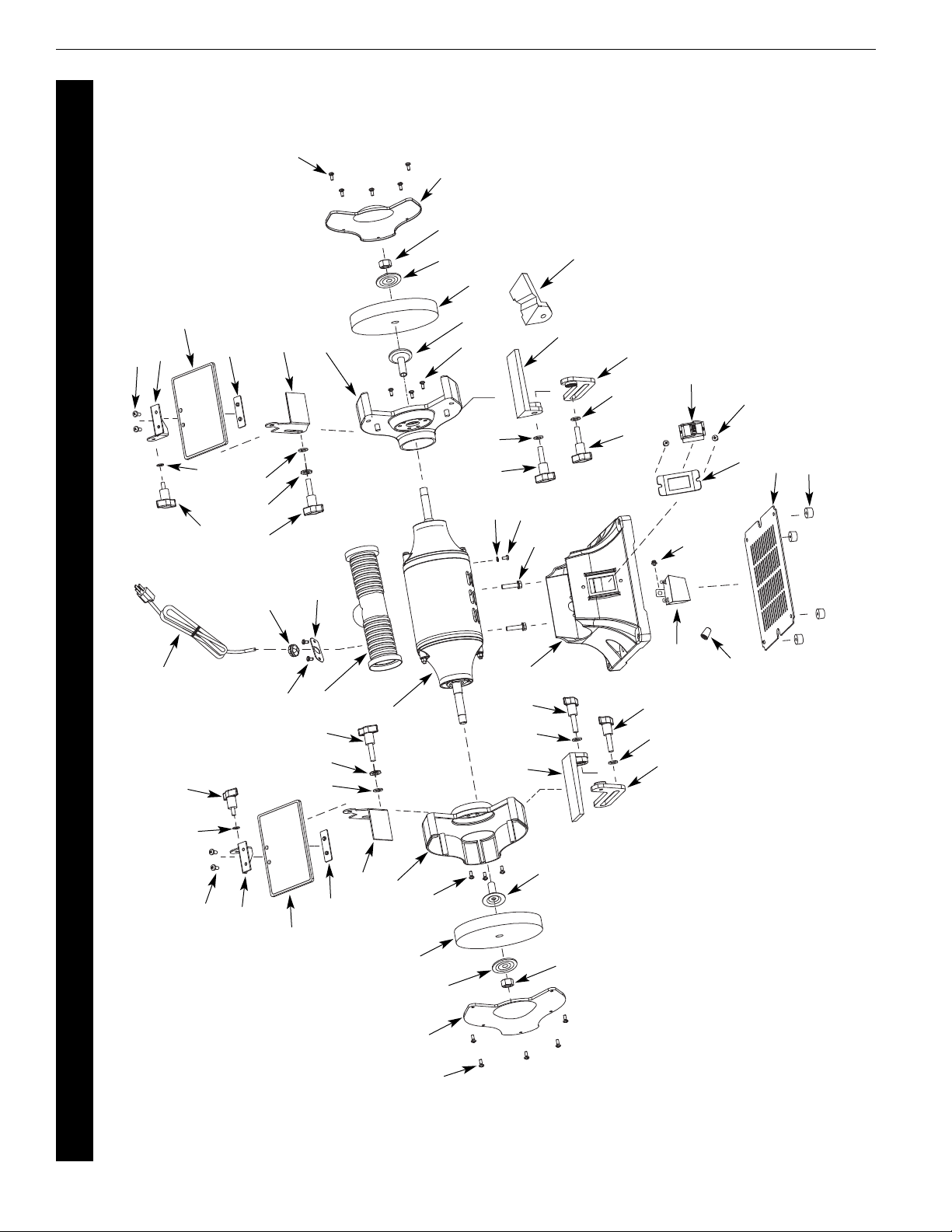
Palmgren Operating Manual & Parts List 9682072A
REPAIR PARTS ILLUSTRATION FOR 9682072A, 6˝ BENCH GRINDER
6
1
2
44
4
43
28
23
17
16
15
46
18
13
26
7
12
11
10
9
8
6
5
4
2
1
24
16
27
14
3
39
33
34
32
38
35
22
20
21
19
10
9
8
7
30
29
12
11
25
15 13
16
48
17
24 26
33
47
20
41
42
14
6
31
16
28
48
Figure 5 – Repair Parts Illustration for 9682072A, 6˝ Bench Grinder

1 Philips Screw, 3/16˝ × 3/8˝ * 10
2 Wheel Guard Cover 9624464.02 2
3 Hex Nut, 1/2˝-12, LH Thread 9600064.00 1
4 Outer Wheel Flange 9618904.00 2
5 Grinding Wheel, 36 Grit, 1/2˝ Bore 9602034.00 1
6 Philips Hex Bolt, Spring Washer, 1/4˝ × 5/8˝ * 6
7 Wheel Guard 9624465.02 2
8 Spark Deflector (Set of 2) 9616841.02 1
9 Eyeshield Plate N/A 2
10 Eyeshield Kit (Includes 9, 10, 12) Set of 2 9632291.01 1
11 Upper Eyeshield Bracket (Set of 2) 9625177.02 1
12 Philips Screw, 3/16˝ × 1/2˝ * 4
13 Flat Washer, 1/4˝ * 2
14 Inner Wheel Flange 9617315.01 2
15 Locking Knob, 1/4˝ × 1/2˝ 9625816.00 2
16 Flat Washer, 3/8˝ * 4
17 Spark Deflector Knob, 3/8˝ × 1/2˝ 9625817.02 2
18 Motor N/A 1
19 Clip Plate 9608099.01 1
20 Philips Screw, 3/16˝ × 1/4˝ * 4
21 Cord Clip * 1
22 Power Cord 9600067.01 1
23 Tool Rest, Left 9625813.02 1
24 Locking Knob, 5/16˝ × 1˝ 9625812.00 2
25 Base N/A 1
26 Flat Washer, 5/16˝ * 2
27 Tool Rest Bracket, Left 9625810.02 1
28 Locking Knob, 3/8 × 1/2˝ 9625817.02 2
29 Grooved Tool Rest, Right 9625825.01 1
30 Tool Rest, Right 9625825.02 1
31 Tool Rest Bracket, Right 9625826.02 1
32 Philips Screw, Spring Washer, M6 × 15 * 2
33 Philips Screw, 3/16˝ × 1/4˝ * 2
34 Star Lock Washer, 3/16˝ * 1
35 Capacitor 9616908.02 1
38 Base Plate 9623758.02 1
39 Rubber Foot 9623991.00 4
41 Switch Plate 9636282.01 1
42 Switch 9608066.01 1
43 Grinding Wheel, 120 Grit, 1/2˝ Bore 9602041.00 1
44 Hex Nut, 1/2˝-12, RH Thread 9600548.00 1
46 Dust Port Assembly 9608070.08 1
47 Wire Nut * 1
48 Spring Washer, 3/8˝ * 2
∆ Operating Instructions & Parts Manual 9643556.01 1
Ref. Part
No. Description Number Qty.
Ref. Part
No. Description Number Qty.
7
Palmgren Operating Manual & Parts List 9682072A
REPAIR PARTS LIST FOR 9682072A, 6˝ BENCH GRINDER
(∆) Not shown.
(N/A) Not available as repair part.
(*) Standard hardware item, available locally.
8
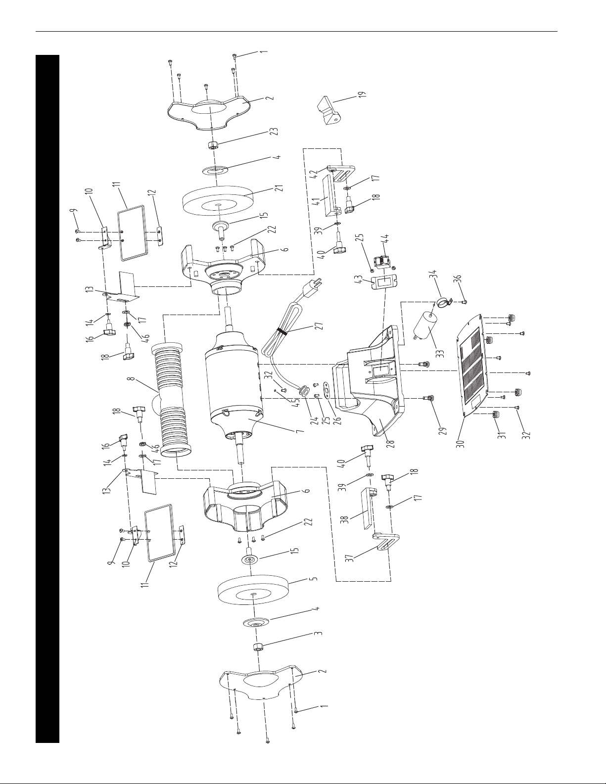
Palmgren Operating Manual & Parts List 9682073A
Figure 6 – Repair Parts Illustration for 9682073A, 8" Bench Grinder
REPAIR PARTS ILLUSTRATION FOR 9682073A, 8" BENCH GRINDER

1 Philips Screw, 3/16˝ × 3/8˝ * 10
2 Wheel Guard Cover 9624496.03 2
3 Hex Nut, 5/8˝, LH Thread 9600088.00 1
4 Outer Wheel Flange 9600089.01 2
5 Grinding Wheel, 36 Grit, 5/8˝ Bore 9602038.00 1
6 Wheel Guard Inner Cover 9626056.02 2
7 Motor Assembly N/A 1
8 Dust Port Assembly 9608070.09 1
9 Philips Screw, 3/16˝ × 1/2˝ N/A 4
10 Eyeshield Mounting Plate (Set-L&R) 9625177.02 1
11 Eyeshield (includes 9, 11, 12) Set of 2 9632291.01 1
12 Eyeshield Plate N/A 2
13 Spark Deflector (Set of 2) 9625815.02 1
14 Flat Washer, 1/4˝ * 2
15 Inner Wheel Flange 9624498.01 2
16 Locking Knob, 1/4˝ × 1/2˝ 9625816.00 2
17 Flat Washer, 3/8˝ * 4
18 Locking Knob, 3/8˝ × 1/2˝ 9625817.02 4
19 Grooved Tool Rest, Right 9625825.01 1
21 Grinding Wheel, 120 Grit, 5/8˝ Bore 9602042.00 1
22 Philips Hex Bolt, Spring Washer, 1/4˝ × 5/8˝ * 6
23 Hex Nut, 5/8˝ * 1
24 Cord Clip * 1
25 Philips Screw, 3/16˝ × 1/4˝ * 4
26 Clip Plate 9608099.01 1
27 Power Cord 9600090.00 1
28 Base N/A 1
29 Philips Hex Bolt, Spring Washer, M6 × 15 * 2
30 Base Plate 9624500.02 1
31 Rubber Foot 9623991.01 4
32 Philips Screw, 3/16˝ × 1/4˝ * 8
33 Capacitor, 125 V/300 UF 9616646.02 1
34 Capacitor Support 9616655.01 1
37 Tool Rest Bracket, Left 9631447.02 1
38 Tool Rest, Left 9625813.02 1
39 Flat Washer, 5/16˝ * 2
40 Locking Knob, 5/16˝ × 1˝ 9625812.00 2
41 Tool Rest, Right 9625825.02 1
42 Tool Rest Bracket, Right 9631448.02 1
43 Switch Plate 9636282.01 1
44 Switch 9608066.01 1
45 Toothed Lock Washer, 3/16˝ * 1
46 Spring Washer, 3/8˝ * 2
∆ Operating Instructions & Parts Manual 9643556.01 1
Ref. Part
No. Description Number Qty.
Ref. Part
No. Description Number Qty.
9
Palmgren Operating Manual & Parts List 9682073A
REPAIR PARTS LIST FOR 9682073A, 8" BENCH GRINDER
(∆) Not shown.
(N/A) Not available as repair part.
(*) Standard hardware item, available locally.

10
Palmgren Operating Manual & Parts List 9682075A
Figure 7 – Repair Parts Illustration for 9682075A, 10" Bench Grinder
REPAIR PARTS ILLUSTRATION FOR 9682075A, 10" BENCH GRINDER

Ref. Part
No. Description Number Qty.
Ref. Part
No. Description Number Qty.
11
Palmgren Operating Manual & Parts List 9682075A
REPAIR PARTS LIST FOR 9682075A, 10" BENCH GRINDER
1 Phillips Screw, Spring Washer, 1/4˝ × 3/4˝ * 10
2 Wheel Guard Cover 9616911.04 2
3 Hex Nut 1˝, LH Thread * 1
4 Outer Wheel Flange 9624480.00 2
5 Grinding Wheel 36 Grit, 1˝ Bore 9602040.00 1
6 Philps Bolt , Spring Washer, 5/16˝ × 3/4˝ * 6
7 Wheel Guard 9626057.01 2
8 Spark Deflector ( Set of 2 ) 9625815.02 1
9 Eyeshield Plate N/A 2
10 Eyeshield Kit (Include 9,10,12) 9632291.01 1
11 Upper Eyeshield Bracket ( Set of 2 ) 9625177.02 1
12 Phillips Screw, 3/16˝ × 1/2˝ N/A 4
13 Flat Washer, 1/4˝ * 2
14 Inner Wheel Flange 9624481.01 2
15 Locking Knob, 1/4˝ × 1/2˝ 9625816.00 2
16 Flat Washer, 3/8˝ * 4
17 Locking Knob, 3/8˝ × 1/2˝ 9625817.02 2
18 Motor N/A 1
19 Cord Clip Plate 9608099.01 1
20 Phillips Screw, 3/16 × 1/4˝ * 4
21 Lead Wire Clip * 1
22 Power Cord N/A 1
23 Tool Rest, Left 9625813.02 1
24 Locking Knob, 5/16˝ × 1˝ 9625812.00 2
25 Base N/A 1
26 Flat Washer, 5/16˝ * 2
27 Tool Rest Bracket, Left 9626290.02 1
28 Locking Knob, 3/8˝ × 1/2˝ 9625817.02 2
30 Tool Rest, Right 9625825.02 1
31 Tool Rest Bracket, Right 9626291.02 1
32 Phillips Bolt, Spring Washer, 5/16˝ × 1˝ * 4
33 Phillips Screw, 3/16˝ × 1/4˝ * 1
34 Toothed Lock Washer, 3/16˝ * 1
35 Dust Port 9608070.10 1
36 Starting Capacitor 9643287.01 1
37 Hex Nut, 1˝, RH Thread * 1
38 Grinding Wheel , 120 Grit, 1˝ Bore 9602043.00 1
39 Spring Washer, 3/8˝ * 2
40 Phillips Screw, 3/16˝ × 1/4˝ * 8
41 Switch 9608066.01 1
42 Grooved Tool Rest, Right 9625825.01 1
45 Running Capacitor 9643289.01 1
48 Base Plate 9616919.02 1
49 Capacitor Support 9642909.01 2
50 Rubber Foot 9632291.00 4
51 Philips Screw, 3/16˝ × 3/8˝ * 2
52 Switch Plate 9636282.01 1
53 Wire Nut 9616899.01 1
∆ Operating Instructions & Parts Manual 9643556.01 1
(∆) Not shown.
(N/A) Not available as repair part.
(*) Standard hardware item, available locally.

PALMGREN ARRANTY
C.H. Hanson / Palmgren warrants their products to be free of defects in material or workmanship. This
warranty does not cover defects due directly or indirectly to misuse, abuse, normal wear and tear, failure to
properly maintain the product, heated, ground or otherwise altered, or used for a purpose other than that
for which it was intended.
The warranty does not cover expendable and/or wear part (i.e. v-belts, screws, abrasives, jaws), damage to
tools arising from alteration, abuse or use other than their intended purpose, packing and freight. The
duration of this warranty is expressly limited to the terms noted below beginning from the date of
delivery to the original user.
The Palmgren branded items carry the following warranties on parts:
All vises, clamps, positioning tables, tombstones, jack screws and vise accessories - LIFETIME.
All bench grinders, drill presses, tapping machines, band saws, lathes, milling machines, arbor presses,
abrasive finishing machines and work stands - 3 YEARS.
The obligation of C.H. Hanson / Palmgren is limited solely to the repair or replacement, at our option, at its
factory or authorized repair agent of any part that should prove inoperable. Purchaser must lubricate and
maintain the product under normal operating conditions at all times. Prior to operation become familiar
with product and the included materials, i.e. warnings, cautions and manuals.
Failure to follow these instructions will void the warranty.
This warranty is the purchaser's exclusive remedy against C. H. Hanson for any inoperable parts in its
product. Under no circumstances is C. H. Hanson liable for any direct, indirect, incidental , special or
consequential damages including loss of profits in any way related to the use or inability to use our
products. This warranty gives you specific legal rights which may vary from state to state.
Palmgren - a C.H. Hanson company
2000 N. Aurora Rd., Naperville, IL 60563 U.S.A.
or call: 1-800-827-3398
Palmgren Operating Manual & Parts List 9682072A, 9682073A and 9682075A
180301

O erating Manual & Parts List 9670100
UNPACKING
Carton should be handled with care to avoid damage from dropping, bumping, etc. Store
and unpack carton with correct side up. After unpacking, inspect carefully for any damage
that may have occurred during transit. Check for loose, missing or damaged parts. If any
damage or loss has occurred, claim must be filed with carrier immediately. Check for com-
pleteness. Immediately report missing parts to dealer.
ASSEMBLY INSTRUCTIONS
ASSEMBLE STAND
Refer to Figure A. Using the screws and washers (1) provided, screw together the footplate
(2) and column (3), as illustrated. Tighten the screws securely. osition stand 9670100
securely.
MOUNT STAND TO SURFACE
Refer to Figure B. Ensure it is steady. Install the stand on a level, stable and robust ground
surface and secure it against falling over with screws that are appropriate for the ground
surface. The screws must securely anchor the stand in the ground surface. (Screws not
included in scope of delivery).
SECURE BENCH GRINDER TO STAND
Using appropriate screws, secure the bench grinder to be attached to the stand. (Screws
not included in scope of delivery).
9644070.01 - 1218
Pedestal Grinder Stand
3
2
1
Figure A Figure B
Base
art #
9642805.01
9670100_oipm_En011_9644070.01 - 12-28-2018__________________________9644070.01 - 12-28-2018_________

PALMGREN WARRANTY
C.H. Hanson / almgren warrants their products to be free of defects in
material or workmanship. This warranty does not cover defects due
directly or indirectly to misuse, abuse, normal wear and tear, failure to
properly maintain the product, heated, ground or otherwise altered, or
used for a purpose other than that for which it was intended.
The warranty does not cover expendable and/or wear part (i.e. v-belts,
screws, abrasives, jaws), damage to tools arising from alteration, abuse or
use other than their intended purpose, packing and freight. The duration
of this warranty is expressly limited to the terms noted below beginning
from the date of delivery to the original user.
The almgren branded items carry the following warranties on parts:
All vises, clamps, positioning tables, tombstones, jack screws and vise
accessories - LIFETIME.
All bench grinders, drill presses, tapping machines, band saws, lathes,
milling machines, arbor presses, abrasive finishing machines and work
stands - 3 YEARS.
The obligation of C.H. Hanson / almgren is limited solely to the repair or
replacement, at our option, at its factory or authorized repair agent of any
part that should prove inoperable. urchaser must lubricate and maintain
the product under normal operating conditions at all times. rior to
operation become familiar with product and the included materials, i.e.
warnings, cautions and manuals.
Fail re to follow these instr ctions will void the warranty.
This warranty is the purchaser's exclusive remedy against C. H. Hanson for
any inoperable parts in its product. Under no circumstances is C. H.
Hanson liable for any direct, indirect, incidental , special or consequential
damages including loss of profits in any way related to the use or inability
to use our products. This warranty gives you specific legal rights which
may vary from state to state.
almgren Operating Manual & arts List 9670100
almgren - a C.H. Hanson Company
2000 N. Aurora Rd., Naperville, IL 60563 U.S.A.
or call: 1-800-827-3398
180301
9670100_oipm_En011_9644070.01 - 12-28-2018__________________________9644070.01 - 12-28-2018_________
This manual suits for next models
2
Table of contents
Other CH Hanson Grinder manuals


Popular Grinder manuals by other brands


Metabo
Metabo WEVF 10-125 Quick Inox Original instructions

Graphite
Graphite 59G062 Translation of the original instructions

Makita
Makita 9521NB Original instructions

Chicago Pneumatic
Chicago Pneumatic CP7540 Series Operator's manual

Metabo
Metabo WPB 13-150 Quick DS operating instructions

Ingersoll-Rand
Ingersoll-Rand CA-EU Series instructions


