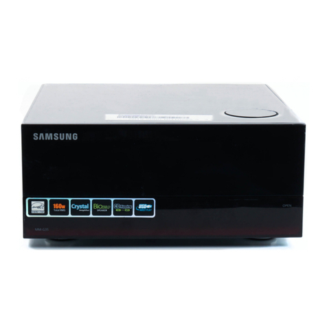
CH Precision D1 SACD/CD User manual

D1 SACD/CD unit
User Manual


Dear Client,
We are honored that you have chosen the CH D1 SACD/CD unit. Our team has put all his e orts into designing and manu acturing
this outstanding product and is proud to present it to you. We hope your D1 will bring you uncountable hours o musical emotion
rom your SACD and CD collection.
But be ore starting your musical journey, we kindly ask you to pay attention to the in ormation contained in this manual. The D1,
as you will discover in the ollowing pages, is a Swiss precision product designed or ultimate per ormance and lexibility. However,
reaching sonic excellence requires your unit to be setup and operated correctly and this what this manual is all about. I you have
any questions or require assistance, please don't hesitate to contact your authorized dealer.
We hope you will enjoy your D1 SACD/CD unit or many years.
The Concert has just begun...
Cossy F.
Heeb T.


Table o contents
1 Technical highlights.............................................................................................................................................................. 7
1.1 SACD/CD drive (VMK-5).............................................................................................................................................. 8
1.2 Mechanical construction............................................................................................................................................... 8
1.3 Modular architecture and slot-in boards........................................................................................................................ 8
1.3.1 Multi-channel support......................................................................................................................................... 9
1.3.2 Digital outputs and CH Link: DIGITAL_OUT board................................................................................................ 10
1.3.3 Stereo analog outputs: ANALOG_OUT board option.............................................................................................10
1.3.4 Monaural analog outputs: Mono ANALOG_OUT board option...............................................................................10
1.3.5 External clock synchronization: SYNC_IO board option........................................................................................ 10
1.4 Power supply............................................................................................................................................................ 11
1.4.1 Optional external power supply......................................................................................................................... 11
2 Be ore use......................................................................................................................................................................... 12
2.1 Package content........................................................................................................................................................ 12
2.2 Sa ety notice............................................................................................................................................................. 12
2.3 User manual............................................................................................................................................................. 13
2.4 Mains supply............................................................................................................................................................. 13
2.5 Transport and packaging............................................................................................................................................ 13
2.6 Cleaning................................................................................................................................................................... 14
2.7 Maintenance and service............................................................................................................................................ 14
3 Installation........................................................................................................................................................................ 15
3.1 Unpacking................................................................................................................................................................ 15
3.1.1 Removing the security screw.............................................................................................................................. 15
3.2 Unit positioning......................................................................................................................................................... 15
3.3 Connections............................................................................................................................................................... 17
3.3.1 CONTROL board................................................................................................................................................ 18
3.3.1.1 USB port.................................................................................................................................................. 19
3.3.1.2 Ethernet port........................................................................................................................................... 19
3.3.2 DIGITAL_OUT boards........................................................................................................................................ 19
3.3.2.1 Standard digital outputs........................................................................................................................... 20
3.3.2.2 CH Link digital audio inter ace.................................................................................................................. 20
3.3.3 Stereo ANALOG_OUT boards............................................................................................................................. 20
3.3.4 Monaural main ANALOG_OUT boards................................................................................................................ 20
3.3.5 SYNC_IO board................................................................................................................................................ 21
3.3.5.1 BNC clock input........................................................................................................................................ 21
3.3.5.2 BNC clock outputs..................................................................................................................................... 21
3.3.6 Power cord receptacle and voltage selection....................................................................................................... 22
3.3.7 External power supply connector....................................................................................................................... 22
4 Operation.......................................................................................................................................................................... 23
4.1 Front panel controls................................................................................................................................................... 23
4.1.1 Front panel...................................................................................................................................................... 23
4.1.2 User control knob............................................................................................................................................. 23
4.2 Operating modes....................................................................................................................................................... 24
4.2.1 Normal mode................................................................................................................................................... 25
4.2.2 Shortcuts.......................................................................................................................................................... 26
4.2.3 Menu mode...................................................................................................................................................... 28
Rev 3.0 D1 User Manual 5

4.3 Con iguration............................................................................................................................................................ 31
4.3.1 D1 con iguration menu items............................................................................................................................ 32
4.3.1.1 AUDIO SETTINGS...................................................................................................................................... 32
4.3.1.2 DISPLAY SETTINGS.................................................................................................................................... 34
4.3.1.3 SHORTCUTS.............................................................................................................................................. 36
4.3.1.4 FACTORY SETTINGS................................................................................................................................... 37
4.3.1.5 INSTALLED OPTIONS................................................................................................................................. 38
4.3.1.6 NETWORK................................................................................................................................................ 38
4.4 Remote control.......................................................................................................................................................... 39
4.4.1 Remote control operation.................................................................................................................................. 39
4.4.2 Changing the remote control batteries................................................................................................................ 40
4.5 Advanced clocking..................................................................................................................................................... 41
4.5.1 General clocking considerations......................................................................................................................... 41
4.5.2 Without SYNC_IO board.................................................................................................................................... 41
4.5.3 D1 SACD/CD drive (with SYNC_IO board) + C1 D/A controller (with SYNC_IO board)..........................................42
4.5.4 Multichannel D1 drive + 3x C1 D/A controllers (all with SYNC_IO board)............................................................43
4.5.5 D1 (with SYNC_IO board) + C1 (with SYNC_IO board) + T1 time re erence.........................................................45
4.6 Returning to actory de aults...................................................................................................................................... 46
5 Firmware update............................................................................................................................................................... 47
5.1 Preparing the USB stick............................................................................................................................................. 47
5.2 Updating the unit's irmware..................................................................................................................................... 47
5.3 Emergency irmware update procedure....................................................................................................................... 48
6 Troubleshooting................................................................................................................................................................. 49
7 Speci ications..................................................................................................................................................................... 50
6 D1 User Manual Rev 3.0

1 Technical highlights
CH products are proudly designed and manu actured in Switzerland by CH Precision Sàrl. Our engineers have put all their know-
how into bringing you the D1, a highest quality modular SACD/CD unit based on slot-in boards and USB lash-drive irmware
update. In its base version the D1 is a pure digital two channel SACD/CD drive to be used with a high quality external Digital to
Analog Converter (DAC). It includes a DIGITAL_OUT board and a CONTROL board. Highest quality playback is ensured when the D1
is paired to the matching CH C1 Digital to Analog Controller using the proprietary high de inition CH Link inter ace.
Optional boards allow to extend the unctionality o the base version o the D1 SACD/CD drive. By adding two monaural
ANALOG_OUT boards or a stereo ANALOG_OUT board the D1 becomes an integrated stereo SACD/CD player. Seamless migration
to multi-channel is achieved by adding urther output boards or the additional surround channels. Up to our output boards can be
placed in the D1. Any combination o stereo (L/R, Ls/Rs or C/Sub) digital (DIGITAL_OUT), main channels monaural (L + R) analog
or stereo (L/R, Ls/Rs or C/Sub) analog (ANALOG_OUT) output boards are allowed. Finally, the SYNC_IO optional board provides
advanced clock synchronization capabilities or use with external clock generators or to enslave the D1 to the C1's master clock or
zero-jitter connection.
D1 main components
(1) External power supply input. For X1 optional external power supply only
(2) Mains switch and power cord receptacle (on back panel)
(3) Adjustment sha ts and screws
(4) Power supply section
Rev 3.0 D1 User Manual 7
(2)
(1)
(3)
(4)
(5)
(6)
(7)
(3)
(8)
(9)
(10)
(3)
(11)
(13)
(3)
(14)
(12)

(5) Main power trans ormer
(6) Standby power trans ormer (ensures green mode Standby)
(7) Esoteric VMK-5 SACD/CD drive mounted on steel support
(8) SACD/CD drawer and AMOLED display (on ront panel)
(9) Audio, clock, USB ( irmware update) and RJ-45 (control) connectors ( rom slot-in boards). Analog ground to Earth jumper
(10) Slot-in boards (SYNC_IO, CONTROL, DIGITAL_OUT, stereo ANALOG_OUT or monaural ANALOG_OUT)
(11) Main board
(12) Power supply regulation board
(13) SACD/CD mechanism control section
(14) Concentric push control knob
1.1 SACD/CD drive (VMK-5
The D1 SACD/CD unit is built around the high-quality Esoteric VMK-5 SACD/CD mechanism eaturing VRDS-Neo disc clamping. The
VRDS disc clamp covers the whole disc (not only its central part) ensuring vibration and error ree digital data reading. CH has
urther improved the vibration immunity o the SACD/CD mechanism by mounting it on a heavy steel rails directly assembled to a
massive steel base plate weighting over 15kg.
1.2 Mechanical construction
The D1 SACD/CD unit is assembled rom high-quality aluminum and steel elements with no visible screws on the ront, top and side
panels. The base o the unit is made o a heavy steel plate whereas the ront panel, the side panels and the top cover are
machined rom aluminum. The power supply is isolated rom the audio section in its own compartment to avoid any contamination
o the audio circuits by noise radiated rom the supply. Pin assembly o all chassis elements provides smooth joints between
elements while screws every 6cm ensures protection against electromagnetic inter erences. First class mechanical and chemical
sur ace treatments provide the luxury inish o the D1.
Four steel eet support the unit. Each eet ends with a elastomer ring to sit on delicate sur aces but is also equipped with a height
adjustable steel spike to ine tune unit positioning. Horizontal adjustment is done with the provided screwdriver through the our
adjustment sha ts accessible rom the top o the unit. In addition to providing convenient horizontal adjustment rom the top o the
unit, the sha ts also serve as vibration evacuation channels or any stacked unit. Special sha t covers are provided to inter ace with
the spikes o the stacked unit. Any vibration rom the upper unit is transmitted by the sha t cover to the sha t and rom the sha t to
the lower unit eet or spike, orming a privileged path or vibrations evacuation.
1.3 Modular architecture and slot-in boards
The D1 bene its rom a ully modular architecture. It eatures separated sections or power-supply, disc mechanism and related
control, ront panel, central host processor and slot-in boards. This modular architecture combined to the USB plug or all irmwares
(MCU, DSP, and FPGA) update allows or easy servicing and upgrade should one section become aulty or obsolete.
The slot-in boards section consists in a vertically mounted mother board with optional boards plugged into it. Optional boards
provide audio unctionality and connectivity to other equipment. There are ive types o slot-in boards:
•CONTROL board: provides a USB port or so tware upgrade and an Ethernet port or command
8 D1 User Manual Rev 3.0

•DIGITAL_OUT: provides two channels o digital audio output. Speci ic back panels or L/R, Ls/Rs or C/Sub channels
•Stereo ANALOG_OUT: provides two channels o analog audio output. Speci ic back panels or L/R, Ls/Rs or C/Sub
channels
•Monaural ANALOG_OUT: provides one ully balanced channel o analog audio output. Speci ic back panels or Le t or
Right channel
•SYNC_IO: provides advanced clock synchronization options (1 clock in, 2 clock out)
There are 6 slots in the D1. A CONTROL board is always installed inside the D1, leaving space or 5 optional boards. One o these
slots is reserved or the SYNC_IO board. Note that optional boards MUST be installed by a quali ied technician. Failure to do so will
void any warranty. Following table shows the typical recommended con igurations or D1:
Con iguration
DIGITAL_OUT L/R
DIGITAL_OUT Ls/Rs
DIGITAL_OUT C/Sub
Mono ANALOG_OUT L
Mono ANALOG_OUT R
ANALOG_OUT L/R
ANALOG_OUT Ls/Rs
ANALOG_OUT C/Sub
Description
SD 9Stereo SACD/CD drive (Base con iguration). To be used with 1 external stereo DAC.
SP 9Stereo SACD/CD player.
DMP 9 9 Dual-Mono SACD/CD player.
MD 9 9 9 Multi-channel SACD/CD drive. To be used with 3 external stereo DACs.
MP 9 9 9 Multi-channel SACD/CD player.
DM-MP 9 9 9 9 Dual-Mono ( or L+R) Multi-channel SACD/CD player.
MH 9 9 9 Multi-channel SACD/CD hybrid drive/player. To be used with 1 external DAC.
D1 recommended configurations (CONTROL board is included in all configurations and SYNC_IO board can be
added in any configuration
1.3.1 Multi-channel support
True multi-channel SACD playback is achieved by means o optional boards. The Stereo versions o D1 are delivered with a single
DIGITAL_OUT board and/or a single ANALOG_OUT board con igured or L/R channels. They can be extended to multi-channel by
simple addition o DIGITAL_OUT or ANALOG_OUT boards or the Ls/Rs and C/Sub channels. No other action is required as the D1
irmware will automatically sense the presence o the additional boards and enable true multi-channel reproduction.
When a D1 has multi-channel capability (either digital, analog or hybrid outputs), it will always select multi-channel DSD layer on
SACDs whenever available. User can then manually change to another available layer (stereo DSD and/or CD layer) rom a given
disc.
Rev 3.0 D1 User Manual 9

When a D1 is purely stereo (either drive or player), it will irst select stereo DSD layer on SACDs whenever available. User can then
manually change to another available layer rom a given disc, including a down-mixed version o the multichannel DSD layer i
this layer exists.
Four channel con igurations are not supported. Multiple output boards o the same type (DIGITAL_OUT or ANALOG_OUT) on any
channel pair (L/R, Ls/Rs or C/Sub) are not supported.
1.3.2 Digital outputs and CH Link: DIGITAL_OUT board
The DIGITAL_OUT board provides digital output or an audio channel pair. Three di erent DIGITAL_OUT boards are available,
corresponding to L/R, Ls/Rs and C/Sub channel pairs. Each DIGITAL_OUT board provides standard digital outputs in AES-EBU,
Coaxial RCA (S/PDIF) and Optical TOSLINK (S/PDIF) ormats as well as in the CH Link high-de inition proprietary ormat. CH Link
uses a dedicated connector to carry high resolution audio and control data over a single link between CH units. It supports both
PCM (up to 768kHz, 32bits) and DSD. To comply with high de inition digital content protection, DSD signals are cyphered when
transported over CH Link rom the D1. Standard digital outputs down-convert DSD signals to 16bits/44.1kHz PCM audio.
1.3.3 Stereo analog outputs: ANALOG_OUT board option
The ANALOG_OUT board provides analog line level output or two audio channels. Three di erent ANALOG_OUT boards are
available, corresponding to L/R, Ls/Rs and C/Sub channel pairs. Each ANALOG_OUT board provides both balanced (on XLR
connectors) and single-ended (on RCA connectors) outputs. Digital to analog conversion is handled by two WM8742 DACs (one per
channel) combined with a discrete dual mono output stage. A choice o digital ilters is available to the user. Filters or PCM and
DSD audio can be selected independently.
1.3.4 Monaural analog outputs: Mono ANALOG_OUT board option
The monaural ANALOG_OUT board pair provides analog line level output or the two main audio channels (Le t and Right). Each
monaural ANALOG_OUT board provides both true balanced (on XLR connectors, with a dedicated analog output stage on each –
warm and cold – point) and single-ended (on RCA connectors) outputs. Each board (i.e. each channel) has its own dedicated
voltage regulators. Digital to analog conversion is handled by one WM8742 DAC on each board combined with a discrete dual
mono output stage. A choice o digital ilters is available to the user. Filters or PCM and DSD audio can be selected independently.
1.3.5 External clock synchronization: SYNC_IO board option
The SYNC_IO board provides advanced clock synchronization options or D1 when used with an external clock generator such as
the CH Precision T1 10MHz time re erence or matching CH DAC (C1). It includes a clock input on BNC connector with selectable 75
Ohm or high input impedance. Supported input requencies on this connector are all standard audio Wordclocks (44.1, 48, 88.2,
96, 176.4, 196, 352.8 and 384 kHz), audio Masterclocks (22.5792 and 24.576 MHz), DSD bitclock (2.8224 MHz) and atomic-
clock multiples (100 kHz and 10 MHz). When ed with an audio Wordclock, the D1's internal clock will lock its VCXO internal clock
in requency and in phase (phase accuracy o +/- 2.5 us), tracking below 0.1 Hz with 0.1 PPM corrections or optimal jitter
rejection.
Two 75 Ohm Wordclock outputs completes the input/output capabilities o the SYNC_IO board.
When a T1 time re erence clock generator is available, ultimate result is achieved when connecting both the C1 and the D1's clock
input to two di erent clock outputs o the T1, and setting both C1 and D1's clock source to SYNCHRO BNC 75. I no ultra-high
10 D1 User Manual Rev 3.0

stability external clock source is available but both C1 and D1 are equipped with a SYNC_IO board, the optimal con iguration is to
set the C1 as the clock master (C1 clock source: INTERNAL), and D1 as the clock slave (D1 clock source: SYNCHRO BNC 75). In that
case, connect one o C1's BNC clock out to D1's clock in con igured as a 75 Ohm input with a 75 Ohm BNC-terminated cable.
1.4 Power supply
The power supply o the D1 is a linear supply with multiple independent local regulations. It is based on an oversized magnetically
shielded toroidal mains trans ormer and includes a mains ilter. A secondary (also toroidal) trans ormer is used as Standby
trans ormer to ensure green Standby mode, meeting the latest energy saving regulations. Both trans ormers have static shields
between primaries and secondaries. They are mounted on a separate steel plate which is isolated rom the main base steel plate by
silent blocks.
Discrete (power-transistor and op-amp based) ultra low noise regulators are used throughout the power supply and special care has
been paid to the master clock power supply. The master clock bene its rom its own dedicated supply, completely decoupled rom
the noisy digital and motor sections. This ensures an ultra-low jitter clock source or the whole system.
Input AC voltage to the power supply can be set to 100V, 115V or 230V AC depending on your local mains voltage.
1.4.1 Optional external power supply
The D1 is equipped with an external power supply input. This input is dedicated to the CH X1 external power supply. When the
external power supply is connected, the internal power supply o the D1 is turned o (only the Standby trans ormer remains
active). Turning the main internal trans ormer o ensures that no power supply induced noise or radiations are generated inside
the D1 unit, thus permitting optimal operating conditions or the circuits. Moreover, the D1's internal voltage regulation stage are
still active, cascaded with the X1's regulation stages, signi icantly lowering the noise loor.
Rev 3.0 D1 User Manual 11

2 Before use
Please read this manual care ully be ore making connections or operating your D1. A ter reading this manual, please store it in an
accessible place or uture re erence. I a ter reading this manual you eel unsure about how to make connections or how to
operate the unit, please contact your authorized dealer or assistance.
2.1 Package content
Make sure that the package content is complete. I not, please contact your authorized dealer. Your package should contain:
•D1 SACD/CD unit
•A power cord
•Four adjustment steel spikes
•A suction cup (used to unscrew the top covers)
•An accessory box containing:
◦an in rared remote control
◦a spike adjustment screwdriver
◦an Allen key
◦a Torx 10 screwdriver
◦our stacking covers
◦a USB stick containing the latest CH Precision irmwares.
◦a set o our CH Support Discs
Please store the packaging or uture use. Check your D1 or any apparent damage. In case o a damage, immediately contact
your authorized dealer. I your D1 is cold due to transport, please let it warm up to room temperature be ore powering it up.
2.2 Safety notice
Make sure to observe the ollowing rules:
•Install your D1 SACD/CD player on a stable base
•Do not install your D1 SACD/CD unit near water
•Always handle with care. The D1 SACD/CD unit is very heavy, so have someone help you when moving it around
12 D1 User Manual Rev 3.0

•Do not expose the unit to any kind o liquid
•Do not install in direct sun light or near any heat source such as radiators or other apparatus generating heat
•Do not install in a con ined space and make sure su icient air can low around the unit
•Do not operate under high ambient temperature (>40C) or with extremely high humidity such as in humid cellars
•Only use options and accessories speci ied or recommended by the manu acturer
•Do not open the unit nor try to service it by yoursel . Do not try to install any option board by yoursel . Always re er to a
quali ied technician or service, maintenance or upgrades. Failure to do so will void the unit's warranty
2.3 User manual
Please read this manual care ully be ore making connections or operating your D1 SACD/CD unit. A ter reading, store the manual
in an accessible place or uture re erence. I , a ter reading this manual, you eel unsure about how to make connections or how to
operate the unit, please contact your authorized dealer.
2.4 Mains supply
Make sure to use 3 terminals (phase, neutral and earth) power cords with ground conductor. Make sure that the mains voltage
selection o the unit matches your mains voltage.
Make sure your D1 SACD/CD unit is disconnected rom AC wall power in the ollowing cases:
•When making connections (it is also recommended to disconnect the rest o the system rom AC wall power)
•When cleaning
•During thunder storms
•When unused or a long period
2.5 Transport and packaging
The D1 SACD/CD unit must always be stored in its original packaging or transportation. Doing so will ensure optimal level o
protection o your unit. There ore, keep all the packaging material in a dry and clean place or uture use.
To avoid any damage to the SACD/CD mechanism, an optical disc must be inserted into the drawer or transportation. We
recommend a blank CD-R.
In addition, the trans ormer base plate must be secured or transportation to avoid excessive constraints on the silent blocks
isolating the chassis rom trans ormer vibrations. This is done by the insertion o a security screw on the bottom o the unit. Do not
orget to install this screw or transportation and to remove it at installation o the unit in its new location.
Rev 3.0 D1 User Manual 13

Finally we recommend to remove the adjustment spikes and to put them into the D1 box or transportation. Indeed, vibrations
during transport may cause the adjustment spikes to move rom their ully retracted position. There is risk o scratching the
installation base i the spikes are not ully retracted when installing the unit.
2.6 Cleaning
Use a so t, dry towel or cloth or cleaning. Never use any solvent or liquids as they may damage the sur ace treatment or
penetrate inside the unit.
2.7 Maintenance and service
The D1 SACD/CD unit contains no user serviceable parts. Do not try to open, modi y or repair your D1 by yoursel . This will void
any warranty. Your D1 SACD/CD player must be checked by a quali ied technician in any o the ollowing cases:
•The unit is not unctioning properly
•The mains cable or the power cord receptacle is damaged
•The unit has been dropped to the loor or presents external damage
•The D1 SACD/CD player has been exposed to liquids (such as rain) or unknown substances
14 D1 User Manual Rev 3.0

3 Installation
3.1 Unpacking
Unpack the D1 SACD/CD unit and store the packaging or uture transportation. Be care ul when li ting the D1 as the unit is heavy
(over 30kg). Get someone to help you i necessary. When unpacking and installing the D1, take care not to damage the high
quality sur ace treatments.
3.1.1 Removing the security screw
The trans ormer base plate must be secured during transportation to avoid damage to the isolating silent blocks. The security screw
is located at the bottom o the unit. To remove the security screw, tilt the unit on its side and unscrew. Do not tilt the unit on the
ront or back panels as this may damage the user control knob or the connectors.
Security screw location
(1) Security screw. Must be mounted or transport and removed at installation
3.2 Unit positioning
When delivered rom actory, the D1 SACD/CD unit's our eet sit on elastomer rings, ensuring both scratch-protection or the base
on which the unit sits, as well as sa e anti-slipping unit positioning.
But a more advanced vibration-channeling mechanical coupling can be implemented, thanks to the steel spikes and the polymer
support discs provided with the D1. To use this optimal coupling, simply go through the ollowing steps:
1. Place the D1 unit on a stable base at its approximate inal position, or instance in your pre erred audio rack. Make sure
cooling air is able to reely low around the unit.
2. Gently li t the unit's corners and insert a support disc under each oot. The oot's elastomer ring should disappear in the
support disc's groove when properly placed. Care ully check all our eet per ectly it in each support disc be ore pursuing
any urther. The unit should stably rest on its eet at that point.
Rev 3.0 D1 User Manual 15
(1)

3. Unscrew the our top covers rom the D1's sha ts with the provided suction cup. Be care ul not to scratch their delicate
inish.
4. Insert the adjustment spikes into each adjustment sha t.
5. So tly screw clockwise each adjustment spikes into the sha t with the provided screwdriver, until any resistance is elt (just
be ore the unit's corner starts to li t).
6. Then screw clockwise each spike by the same amount ( or instance two ull turns).
7. I the base is lat, the unit should be stable and horizontal. I not, correct the unit's stability and horizontality by turning
clockwise or anti-clockwise the required spikes.
8. I no CH Precision unit is to be stacked on top o the D1, screw the our top covers back. Otherwise, screw the our
polymer stacking caps instead, and gently lay down the unit to be stacked on top o it. Be very care ul that both units are
per ectly aligned in order not to scratch the D1's top plate with the other unit's eet. Repeat steps 3 to 8.
Adjustment shafts, feet and spikes
(1) Adjustment sha ts. Insert adjustment spikes and use screwdriver to secure and adjust individual eet spikes
(2) Feet
(3) Adjustment spike heads (when inserted into adjustment sha ts)
(4) Adjustment spike
Never stack any component other than CH's on your D1. Never use the aluminum sha t covers (top covers) when another CH
component is to be stacked on top o your D1.
16 D1 User Manual Rev 3.0
(1)
(1)
(1)
(1)
(2)
(3) (3)
(3) (3)
(2) (2)
(2)
(4)

Shaft covers (left: stacking cover, right: top cover
3.3 Connections
This section provides in ormation about how to connect your D1 SACD/CD unit to your system. As the D1 is a modular design with
di erent optional boards, the description applies to the example con iguration presented below. I your options do not match the
example or you don't eel secure with the connections to be applied to your con iguration, please contact your authorized dealer
or assistance.
The example con iguration is a ull eatured multi-channel con iguration with 3x DIGITAL_OUT boards (L/R, Ls/Rs, C/Sub), 1x
ANALOG_OUT (L/R) board and clock synchronization option (SYNC_IO board). This is one o the most complete con igurations o
D1. I your con iguration does not include some o the presented options, just discard the corresponding connections.
Rear panel connections
(1) Ethernet port or command inter ace. Unused or now. [CONTROL board]
(2) BNC clock input. Provides 75 Ohm or Hi-Z input. [optional SNYC_IO board]
(3) TOSLINK (S/PDIF) digital output or L/R channels [DIGITAL_OUT board or L/R channels]
(4) AES-EBU digital output or L/R channels [DIGITAL_OUT board or L/R channels]
(5) TOSLINK (S/PDIF) digital output or Ls/Rs channels. [optional DIGITAL_OUT board or Ls/Rs channels]
(6) AES-EBU digital output or Ls/Rs channels. [optional DIGITAL_OUT board or Ls/Rs channels]
(7) TOSLINK (S/PDIF) digital output or C/Sub channels. [optional DIGITAL_OUT board or C/Sub channels]
(8) AES-EBU digital output or C/Sub channels. [optional DIGITAL_OUT board or C/Sub channels]
Rev 3.0 D1 User Manual 17
(1) (2) (3) (4) (5) (6) (7) (8) (9) (10) (12) (13)
(14) (15) (16) (17) (18) (19) (20) (21) (22) (23) (24) (27) (28)
(11)
(25) (26)

(9) Balanced analog output or L channel. [optional ANALOG_OUT board or L/R channels]
(10) Single-ended analog output or L channel. [optional ANALOG_OUT board or L/R channels]
(11) Earth connector. Internally connected to digital ground
(12) External power supply connector or X1 power supply option
(13) Power on/o switch
(14) USB port or so tware upgrades. [CONTROL board]
(15) BNC 75 Ohm clock output 2. [optional SYNC_IO board]
(16) BNC 75 Ohm clock output 1. [optional SYNC_IO board]
(17) CH Link digital output or L/R channels. [DIGITAL_OUT board or L/R channels]
(18) Coaxial (S/PDIF) digital output or L/R channels. [DIGITAL_OUT board or L/R channels]
(19) CH Link digital output or Ls/Rs channels. [optional DIGITAL_OUT board or Ls/Rs channels]
(20) Coaxial (S/PDIF) digital output or Ls/Rs channels. [optional DIGITAL_OUT board or Ls/Rs channels]
(21) CH Link digital output or C/Sub channels. [optional DIGITAL_OUT board or C/Sub channels]
(22) Coaxial (S/PDIF) digital output or C/Sub channels. [optional DIGITAL_OUT board or C/Sub channels]
(23) Balanced analog output or R channel. [optional ANALOG_OUT board or L/R channels]
(24) Unbalanced analog output or R channel. [optional ANALOG_OUT board or L/R channels]
(25) Analog ground connector 2
(26) Analog ground connector 1.Can be connected to digital ground (Earth) using provided jumper
(27) Power use and voltage selection
(28) Power cord receptacle
The CONTROL board is mandatory in any D1 SACD/CD unit con iguration and is always actory installed. Depending on optional
boards and their arrangement in the D1's expansion slots, connector arrangement may di er on your unit. Each D1 unit provides
5 expansion slots supporting any combination o the ollowing optional boards (note that one slot is dedicated to the SYNC_IO
board):
•Stereo DIGITAL_OUT boards or L/R, Ls/Rs or C/Sub channels
•Stereo ANALOG_OUT boards or L/R, Ls/Rs or C/Sub channels
•Monaural ANALOG_OUT Le t and Right boards (must be used together as a pair)
•SYNC_IO board or external clock synchronization
Note that only one SYNC_IO board is allowed. Each pair o channels (L/R, Ls/Rs or C/Sub) can support a DIGITAL_OUT and/or an
ANALOG_OUT board. Optional output boards can be placed in any slot. Installation o optional boards must be done by a quali ied
technician only. Do not attempt to install any optional board by yoursel as this would void the unit's warranty.
3.3.1 CONTROL board
The CONTROL board is actory installed into the D1. It provides a USB port or so tware updates and an Ethernet port or
controlling the unit over a network. Following drawing shows the layout o the back panel o the CONTROL board:
18 D1 User Manual Rev 3.0

CONTROL board back panel layout
3.3.1.1 USB port
The USB port on the CONTROL board is dedicated to the irmware update o the D1 unit. Do not use it or any other purpose. For
more in ormation on unit irmware update, please re er to the corresponding section o this manual.
3.3.1.2 Ethernet port
The Ethernet port on the CONTROL board is dedicated to network based control o the unit. This unctionality is currently not
implemented, thus leave the Ethernet port unconnected. A uture D1 irmware release will provide this unctionality.
3.3.2 DIGITAL_OUT boards
DIGITAL_OUT boards provide digital audio output capabilities. Additional DIGITAL_OUT boards or Ls/Rs and C/Sub channels can
be added to the de ault actory installed DIGITAL_OUT L/R into D1 or ull digital high-de inition multi-channel support.
DIGITAL_OUT boards provide both standard (AES-EBU, Coaxial and Optical) digital audio outputs and a proprietary (CH Link) high-
de inition digital audio inter ace. Following drawing shows the layout o the DIGITAL_OUT board connectors and naming or the
di erent channel pairs:
DIGITAL_OUT boards back panel layout for L/R, Ls/Rs and C/Sub channels
Rev 3.0 D1 User Manual 19

3.3.2.1 Standard digital outputs
Each DIGITAL_OUT board provides three standard digital outputs: AES-EBU (carrying consumer encoding), Coaxial (S/PDIF) and
Optical (TOSLINK). Digital output is ixed at 16bits/44.1kHz on all standard outputs. I an SACD is played in the D1, the DSD
stream is down converted to 16bits/44.1kHz on the standard digital outputs. When a CD is played, the data rom the disc is
directly trans erred to the standard digital outputs.
3.3.2.2 CH Link digital audio interface
Each DIGITAL_OUT board includes a CH Link proprietary digital audio inter ace. This inter ace carries both complete audio stream
and control in ormation. Use this link as the pre erred inter ace when connecting your D1 to other CH units such as C1 converters.
The proprietary CH Link digital audio inter ace allows or high de inition uncompressed digital audio trans er and supports both
DSD and PCM (up to 705.6 / 768 kHz). For digital content protection reasons, the CH Link inter ace cyphers the native DSD stream
rom SACD when trans erring such data.
3.3.3 Stereo ANALOG_OUT boards
ANALOG_OUT boards provide analog audio output capabilities. ANALOG_OUT boards or L/R, Ls/Rs and C/Sub channel pairs can
be installed into D1 or analog stereo or multi-channel support. DIGITAL_OUT, stereo ANALOG_OUT and monaural ANALOG_OUT
boards can be combined, providing or instance digital output on the main (L/R) channels and analog out on Ls/Rs and C/Sub
channels. Stereo ANALOG_OUT boards provide both balanced (XLR) and single-ended (RCA) analog audio outputs. Following
drawing shows the layout o the Stereo ANALOG_OUT board connectors and naming or the di erent channel pairs:
Stereo ANALOG_OUT boards back panel layout for L/R, Ls/Rs and C/Sub channels
3.3.4 Monaural main ANALOG_OUT boards
ANALOG_OUT boards provide analog audio output capabilities. Monaural ANALOG_OUT board pairs or Le t and Right channels
can be installed into D1 or analog support on main channels. DIGITAL_OUT, stereo ANALOG_OUT and monaural ANALOG_OUT
boards can be combined, providing or instance monaural analog output on Le t and on Right channels, and stereo analog output
on Ls/Rs and C/Sub channels. Monaural ANALOG_OUT boards provide true ully-balanced (XLR), single-ended 75 Ohm (RCA) and
single-ended 50 Ohm (BNC) analog audio outputs. Following drawing shows the layout o the Monaural ANALOG_OUT board
connectors and naming:
20 D1 User Manual Rev 3.0
Table of contents

