Challenger CH-1 User manual

1
Challenger
CH-1
Product Manual
Challenger
Model No. CH-1
Product Manual
Edition 1 –August 2023

2
Challenger
CH-1
Product Manual
This Product Manual is an integral part of the product kit.
CHISELfit reserves the right to modify its products and documentation at any time and
without notice.
CHISELfit will accept responsibility for the product only if the following precautions are
observed:
-The product is used in compliance with its specifications.
-The product is used in compliance with the intended purpose as illustrated and
explained in this Product Manual
-Every part of the Product Manual has been carefully read.
-The place of installation meets the requirements in this Product Manual.
-Proper clothing is worn during usage.
CHISELfit is not responsible for any harm due to any failures or damage caused by
unauthorized maintenance, misuse, accident, negligence, improper assembly or
installation, rust or corrosion as a result of the product’s location, alterations or
modifications without CHISELfit’s written authorization or caused by failure on your part
to use, operate and maintain the product as set out in this product manual.
The Challenger is protected by U.S. Patent No. 10,653,914 B2 and U.S. Patent
No. 11,524,206. Other U.S. and worldwide patents pending.

3
Challenger
CH-1
Product Manual
Table of contents
Table of contents…………………………………………………………………………….3
Usage location and space requirements………………………………………….4
Unboxing and assembly instructions……………………………………………….6
Moving the machine……………………………………………………………………….15
Leveling the machine………………………………………………………………………17
Safety instructions…………………………………………………………………………..18
Product Introduction……………………………………………………………………….19
Operating instructions and information…………………………………………..20
Console functions and operation……………………………………………………..28
Maintenance……………………………………………………………………………………33
Troubleshooting……………………………………………………………………………….34
Technical specifications……………………………………………………………………34
Product label and serial number location…………………………………………35
Service parts and technical support………………………………………………….35

4
Challenger
CH-1
Product Manual
Usage location and space requirements
For convenience of placement, read and consider the following usage location and
space requirements before unboxing Challenger.
The Challenger must be installed and used in a location that meets the following
requirements.
-Temperature of between 50°F (+10°C) and 80°F (+ 27°C).
-Adequate lighting.
-An open space perimeter of at least 24” (60cm) around the base frame of
Challenger.
-A rigid and stable flat surface that is vibration free and capable of supporting the
combined weight of Challenger and a user mounted on Challenger, given
Challenger’s weight of 395 lbs. (175 kgs) and a maximum user weight of
350 lb.s (159 kgs.)
Do not install Challenger on a soft or floating floor.
Do not expose Challenger to direct sunlight.
Do not use Challenger outdoors or leave Challenger outside or exposed to weather
elements.
Do not place Challenger in high moisture indoor environments such as near
swimming pools, hot tubs, saunas or shower areas.
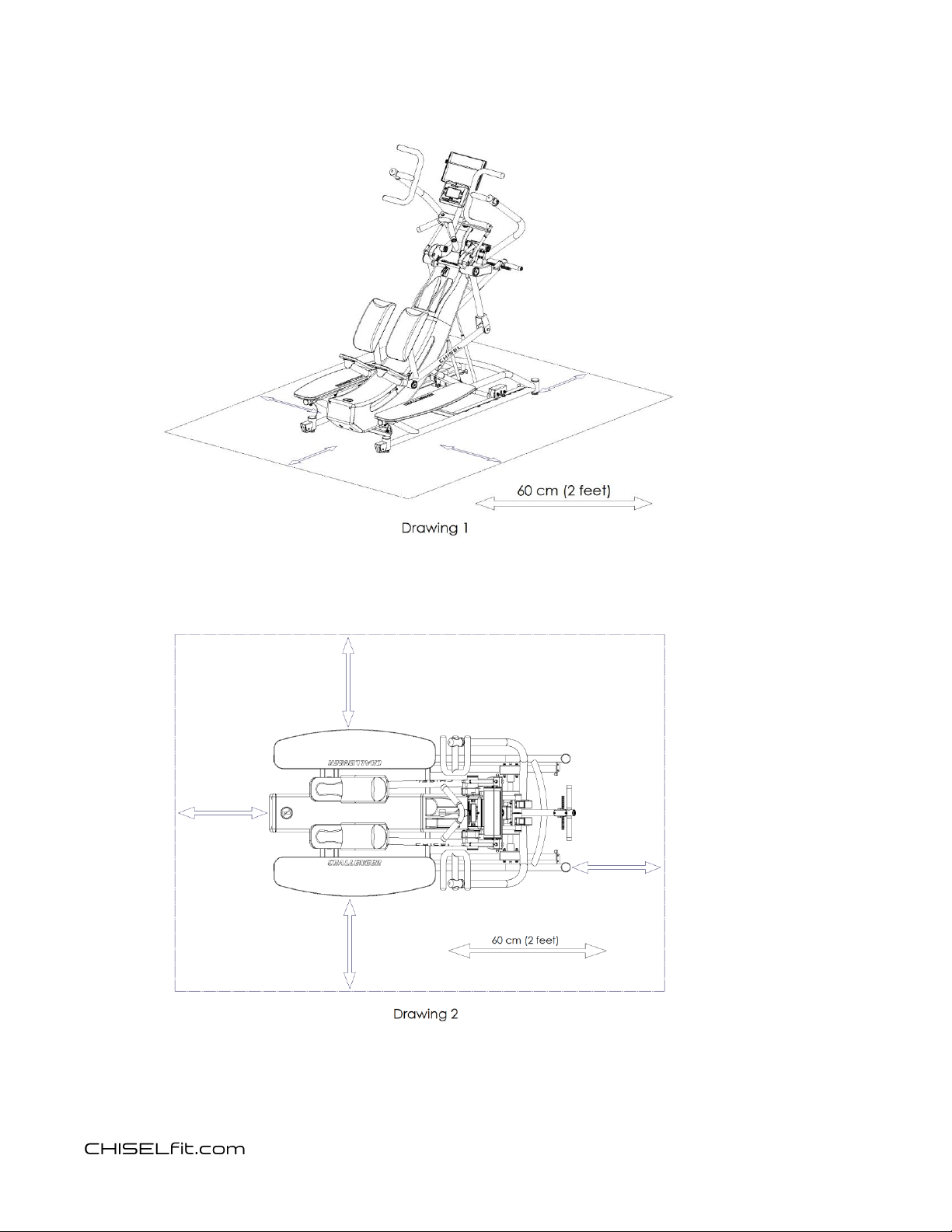
There should be no people, pets or objects within the exercise area as illustrated
below in drawings 1 and 2. If anything enters the exercise area stop exercising on
Challenger immediately and do not resume exercising on Challenger until the
exercise area is clear.
5
Challenger
CH-1
Product Manual
Exercise space requirements

6
Challenger
CH-1
Product Manual
Unboxing and Assembly Instructions
*Two people each capable of lifting at least 100 lbs. / 45 kg. are required to
assemble Challenger. Never attempt to assembly Challenger alone.
*Never open box when it is on its side.
1. Remove all of the unassembled components and the hardware pack and
place them in the work area such that each part is easily identifiable.
2. With the exercise frame still in its lowest position, carefully cut away the
dust cover bag from the exercise frame such that entire top of the
exercise frame is exposed. Be careful not to damage any components of
the machine when cutting away the bag.
3. With the exercise frame still in its lowest position, remove the small
vertical card board tubes supporting the left and right side upper swing
arms and lower swing arms.
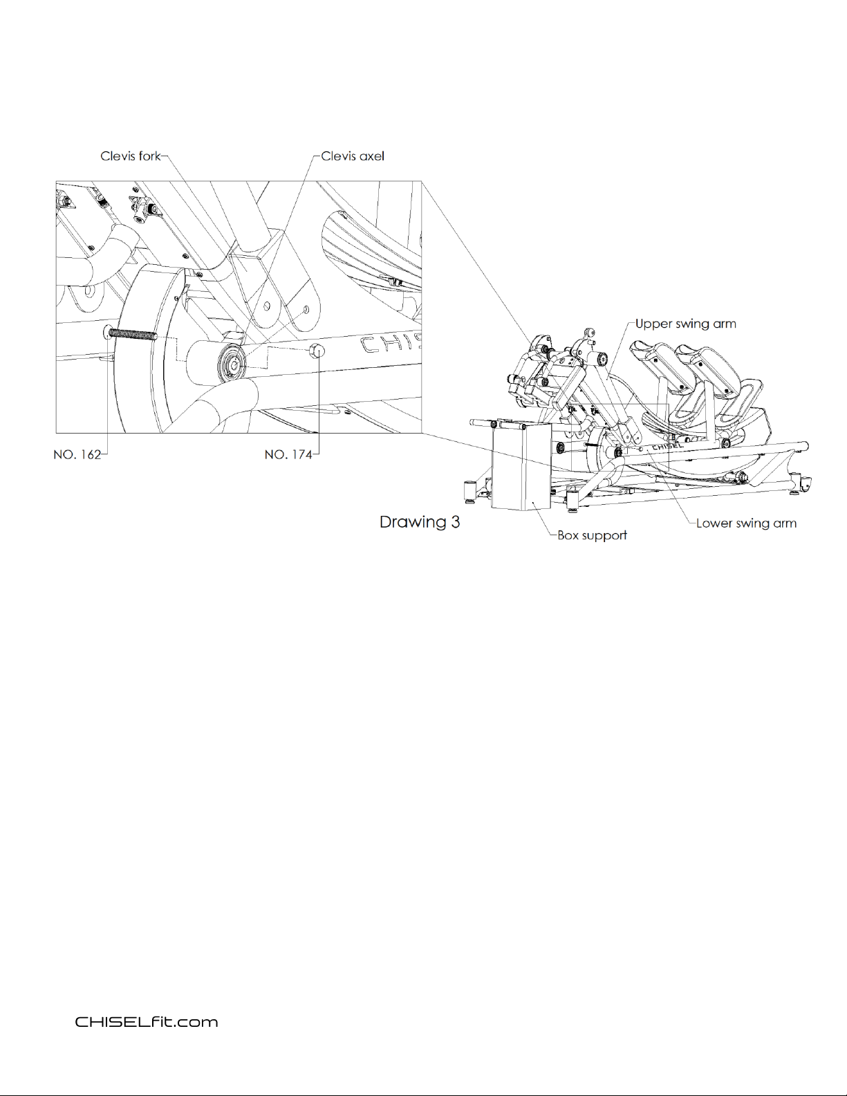
4. As illustrated in drawing 3, connect the lower swing arms to the upper
swing arms by fastening the lower swing arms clevis axles to the upper
swing arms clevis forks with a No. 162 bolt and No. 174 acorn nut. Make
certain that the acorn nuts are securely fastened on the outer side of
the clevis forks as illustrated.
7
Challenger
CH-1
Product Manual
5. With the exercise frame still in its lowest position, screw the threaded
end of each gas spring into each attachment clevis as illustrated in
drawing 4. Once the gas springs are fully threaded into each attachment
clevis allow the bottom end of each gas spring to rest against the curved
cross frame bar.
6. Retrieve 2 each No. 143 bolts and 2 each No. 169 nuts from the
hardware pack and have them at the ready.
7. With the first assembly person ready with the No. 143 bolts and No. 169
nuts, the second assembly person will grasp the black angle adjustment
lifting handles and squeeze the yellow latching levers against the black
lifting handles. While squeezing the yellow latching levers, lift the angle
adjustment arm off of the cardboard support and move the exercise
frame up to its highest angle.

8
Challenger
CH-1
Product Manual
8. As also illustrated in drawing 4, while the second assembly person is
holding the exercise frame in its highest position, the first assembly
person will connect the lower ends of the gas springs to the lower
attachment brackets with the No 143 bolts and No. 169 nuts. Make
certain the No. 169 nuts are securely fastened to the No. 143 bolts.
Attaching the gas springs

9
Challenger
CH-1
Product Manual
9. As illustrated in drawing 5, securely fasten each left and right mounting step to the
mounting step support frame with 4 each No. 131 bolts.
10
Challenger
CH-1
Product Manual
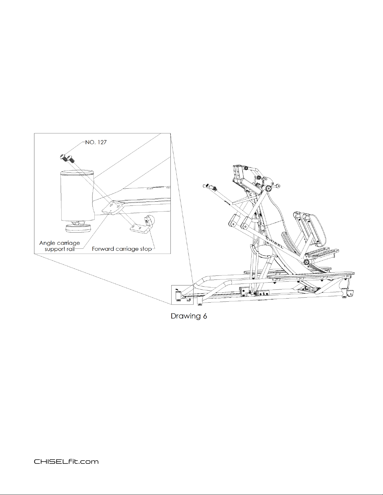
10. As illustrated in drawing 6, securely fasten the left and right forward carriage
stops to the angle carriage support rail with 2 each No. 127 screws.
11
Challenger
CH-1
Product Manual
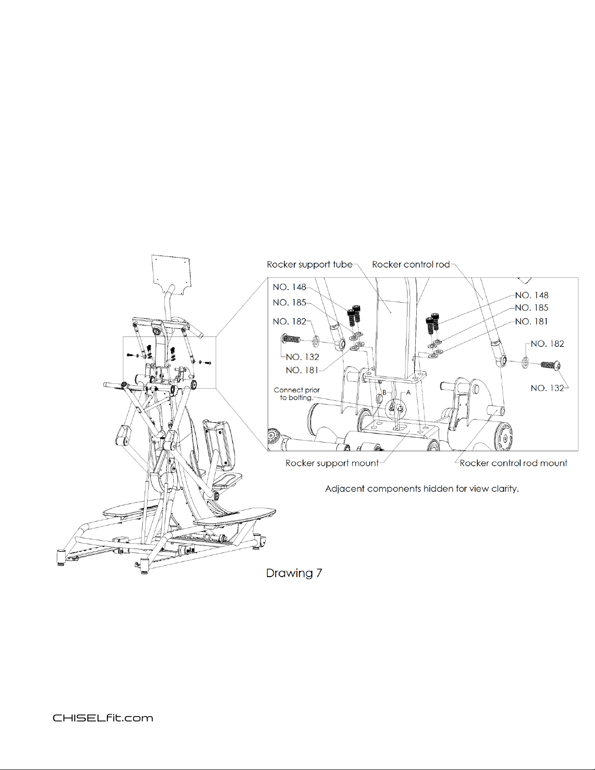
11. As illustrated in drawing 7, while the first assembly person is holding the rocker
support tube above the rocker assembly mounting bracket, the second assembly
person will securely connect console cable A with console cable B and guide the
cable connection down into the opening in the rocker mount.
12. Securely fasten the rocker support tube to the rocker support mount with 4 each
148 bolts, 4 each 185 lock washers and 4 each 181 flat washers.
13. Securely connect each left and right rocker control rod to each left and right
rocker control rod mount with a No. 132 bolt and a No. 182 washer.
12
Challenger
CH-1
Product Manual
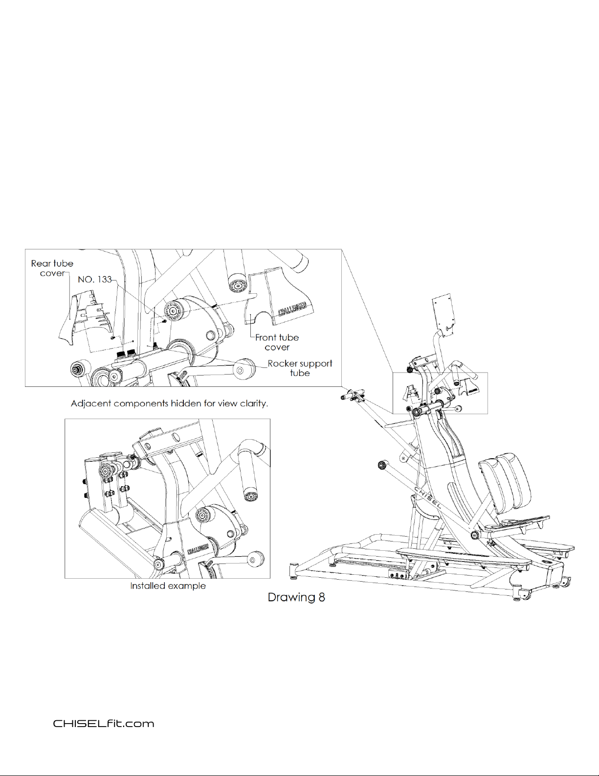
14. As illustrated in drawing 8, place the front tube cover against the front of the
rocker support tube and ensure that it fits flush with the adjacent plastic guard
below it.
15. Place the rear tube cover against the rear of the rocker support tube such that the
front tube cover and the rear tube cover interlock and fit flush against one
another.
16. Securely fasten the front tube cover to the rear tube cover with 2 each no. 133
screws through the left and right slots located on the front tube cover.
13
Challenger
CH-1
Product Manual
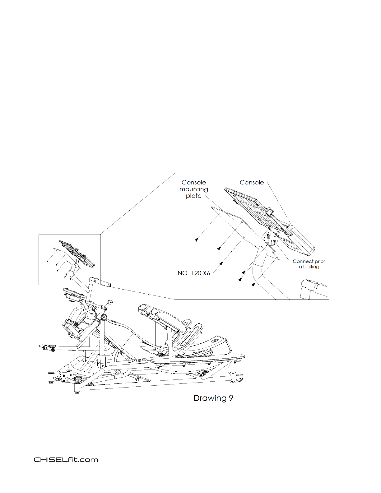
17. Install the 4 each provide AA batteries into the battery compartment located on
the back side of the console.
18. As illustrated in drawing 9, while assembly person one holds the console
suspended above the console mounting plate, assembly person two will connect
the data cable extending from the back side of the console to the data cable
extending from the console support tube. Guide the data cable connection into
console support tube.
19. Securely fasten the console to the console mounting plate with 6 each No. 120
screws.
14
Challenger
CH-1
Product Manual
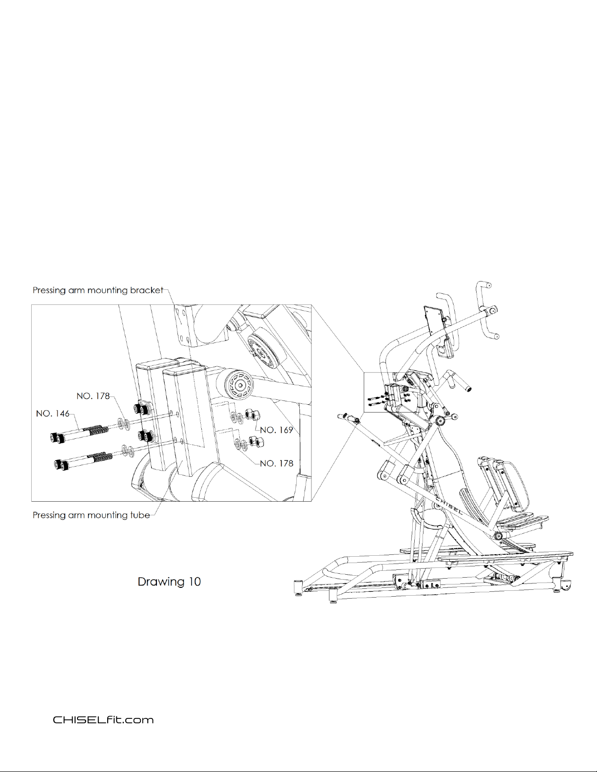
20. As illustrated in drawing 10, mount the left and right pressing arms by loosely
fastening each pressing arm mounting bracket to each pressing arm mounting tube
with 4 each No. 146 bolts, 8 each No. 178 washers and 4 each No. 169 nuts.
Leaving the bolts loosely fastened will make it easier to line up all 4 bolts to get
them installed.
21. Once all 4 bolts are installed in each press arm, securely tighten all 8 each No. 146
bolts to the 8 each No. 169 nuts.

15
Challenger
CH-1
Product Manual
Moving the machine using the built in transport wheels
Never attempt to move the Challenger machine alone! Two persons each capable of
lifting at least 100 lbs. / 46 kgs. are required to move Challenger.
A minimum, constant and unobstructed ceiling height of 96 in. / 244 cm of the entire
intended path of movement is required to move Challenger. Prior to moving Challenger
observe any lighting fixtures or other objects hanging from the ceiling or any doorways in
the projected movement path that may encroach on the required 96 in / 244 cm ceiling
height.
1. Prior to moving Challenger, adjust the exercise motion frame to angle position
“9” and ensure that the yellow angle adjustment latching lever is engaged such
that the exercise motion frame is securely locking into position “9”.
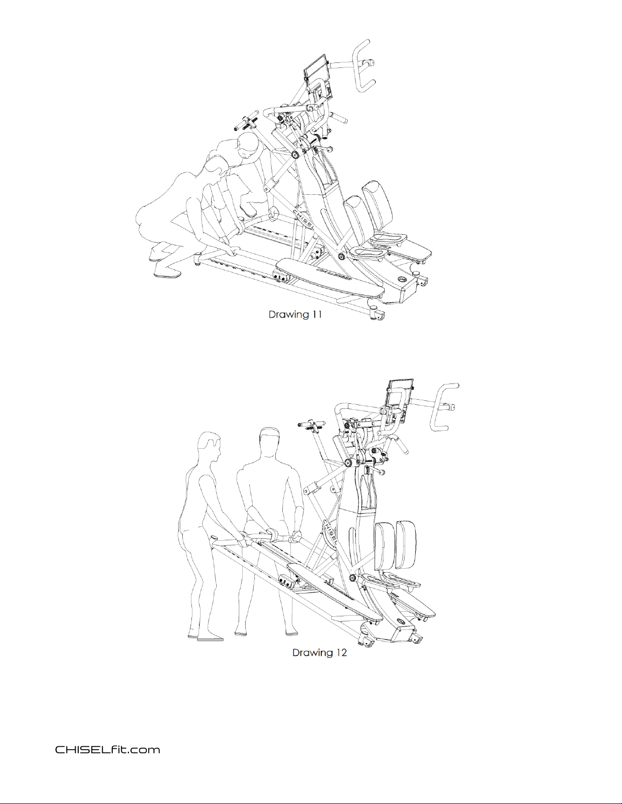
2. As illustrated in drawings 11 and 12, each of the two persons moving Challenger
should simultaneously lift the front end of Challenger by grasping the base
frame as illustrated and lifting the front end of Challenger until the rear
transport wheels are engaging the floor surface such that the rear
transportation wheels are the only parts of Challenger that are contacting the
floor surface.
3. While holding the Challenger base frame in the angled position with the
transport wheels contacting the floor, roll Challenger to the desired location
and gently lower the front end of the base frame to the floor surface.
16
Challenger
CH-1
Product Manual
17
Challenger
CH-1
Product Manual
Leveling Challenger
After placing Challenger in the usage location, check to make sure that all 4 leveling feet
are touching the floor such that Challenger is stable on the floor.
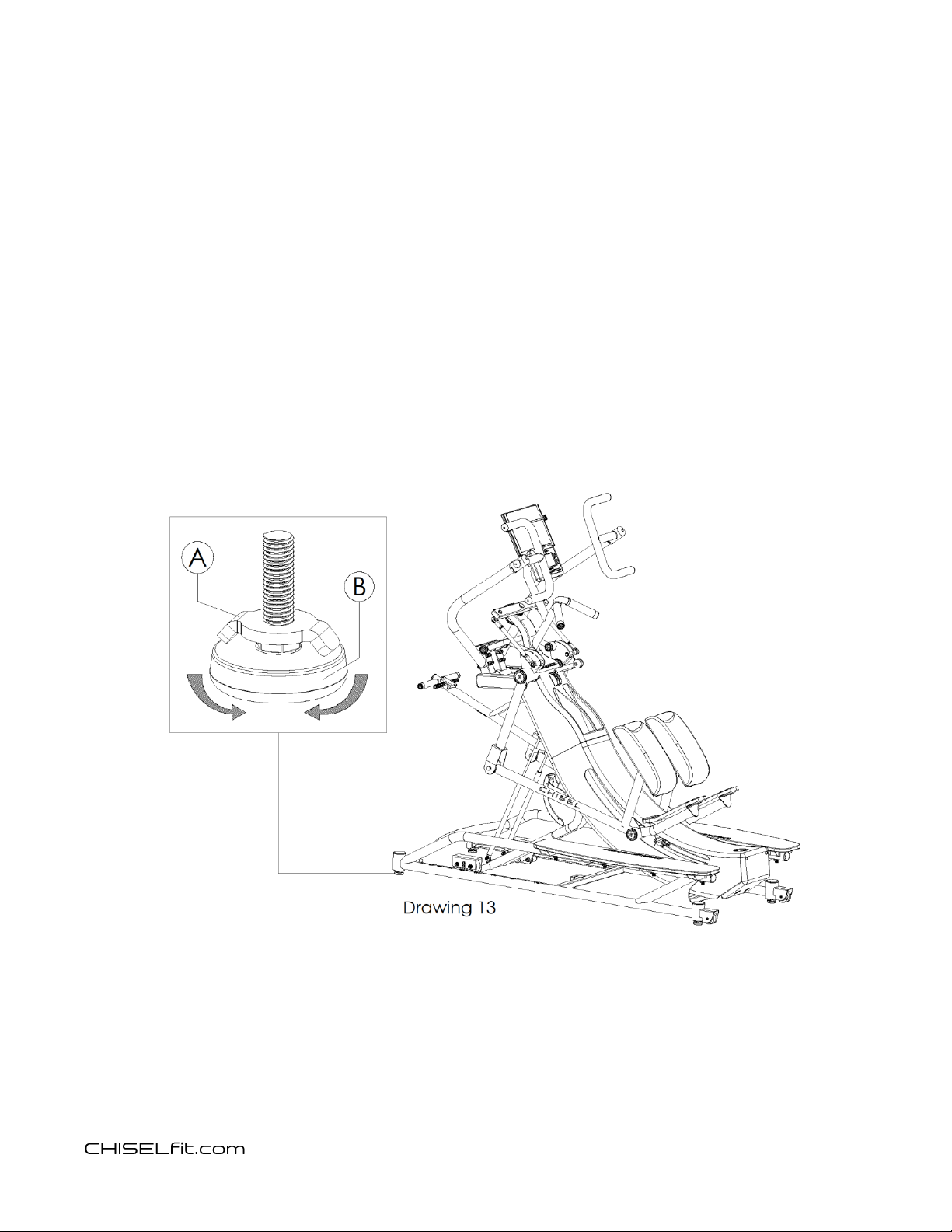
If any of the leveling feet require adjustment, refer to drawing 13 and follow these steps.
-Loosen the locking wing nut (A).
-Screw or unscrew the leveling foot (B) until the frame is stable on the floor surface.
-Tighten the locking wing nut (A).

18
Challenger
CH-1
Product Manual
Safety instructions
General safety
Use Challenger exclusively for the purposes described in the user manual; only perform
the exercises for which the product has been designed, following the instructions
provided in this manual. Any other use is to be considered inappropriate and therefore
dangerous.
Never use Challenger if the product is not working properly or any components appear to
be worn, loose or damage. If you are in a commercial fitness facility, please alert a staff
member if Challenger is not working properly. If you own Challenger for personal use,
please contact CHISELfit product support at chiselfit.com for service. Do not use
Challenger until all necessary service has been performed by a CHISELfit authorized and
approved service technician using authorized and approved CHILSEfit components.
Do not allow children to have unsupervised access to the Challenger. Keep children away
from Challenger. Challenger is not intended for users under 15 years of age.
For commercial fitness facility usage, please ensure that all facility patrons have access to
all of the safety information written in this manual prior to operating Challenger.
Personal safety
Before beginning any exercise program, consult with a medial healthcare professional to
ensure your personal readiness.
Never attempt to exceed your personal performance capabilities. If you feel unwell,
experience dizziness or chest pain at any point while using Challenger, stop exercising
immediately and seek medical attention.
Read all instructions before operating Challenger. These instructions are provided to
ensure the safety of the user and protect the product. If you do not fully understand any
part of this manual or how to safely operate Challenger, ask a qualified staff member to
explain anything about Challenger that you do not fully understand.
Plan the workout according to your physical characteristics and state of health, beginning
with less demanding resistance levels. Only increase the resistance level and workout
intensity on Challenger after you become familiar with how your body reacts to the
exercise function.

19
Challenger
CH-1
Product Manual
While operating Challenger, other people must remain at a safe distance.
Do not operate Challenger when children or pets are present.
In a commercial fitness facility environment, a qualified staff member must explain
proper and improper use of Challenger.
Product Introduction

20
Challenger
CH-1
Product Manual
Operating instructions and information
The CHISELfit Challenger must only be used for the purpose for which it was
designed and produced: aerobic, strength and stretching exercises of the lower
and upper limbs and torso. Any other use is to be considered inappropriate and
therefore dangerous.
Refer to the following instructions and corresponding drawing illustrations to
understand how to safely operate Challenger.
Instructions for getting on and off of Challenger
*Do not attempt to mount Challenger from the rear of the machine. Doing so
could result in severe injury and possible damage to the machine.
*Do not step on or off of the machine when the pedals are moving. Doing so could
result in severe injury.
*Do not step on or place anything on the plastic center arch shaped section of the
exercise frame between the pedals. Doing so could result in severe injury and
possible damage to the machine.
1. As illustrated in drawings 14-16, enter from the side by first stepping onto
either side mounting step and grasping the exercise arm handle closest to you
with one hand.
2. Next while stand with both feet on the mounting step, reach out and grasp the
other exercise arm handle with your other hand.
3. Next while firming grasping and controlling each exercise handle, step over the
exercise pedal nearest you and onto the other pedal. Firmly controlling the
exercise arms handles during mounting will minimize movement of the exercise
pedals and make it easier to get into the exercise position.
4. Next step onto the other exercise pedal.
5. When fully mounted in the exercise position, each hand should be grasping an
exercise arm handle and each foot should be mounted on an exercise pedal
with each ankle and shin snug against a shin/ankle pad.
Table of contents


