Chandler Limited TG MICROPHONE CASSETTE User manual

For more information, visit www.chandlerlimited.com. © 2017 Chandler Limited, Inc. All Rights Reserved. UM TGMC-120117
Abbey Road Studios, EMI, TG, Curve Bender and their associated logos are trademarks of EMI (IP) Limited.
OUTPUT
48v
DI
LINE
PHASE
BYPASS
SHARP
ATTACK RELEASE
HOLD
ROUNDED
TREBLE
PRESENCE
BASS
EQ IN
OUTPUT
564
3
2
1
0
7
8
9
10
IN
-8
-6
-4
-2 0
+2
+4
-10
+6
+8
+10
-8
-6
-4
-2 0
+2
+4
-10
+6
+8
+10
1
2
3
4
567
8
9
10
11 1
2
3
4
567
8
9
10
11
1
2
3
4
567
8
9
10
11
-10
-9
-8
-7
-6 -5 -4
-3
-2
-1
0
COARSE GAIN
FINE GAIN
-8
-6
-4
-2 0
+2
+4
-10
+6
+8
+10
300
500 1.2
3.6
6.5
OUT
RUMBLE FILTER
-8
-6
-4
-2 0
+2
+4
-10
+6
+8
+10
OUT
33
41 47
65
82
110
OPTO
®
+30
+35 +40 +45
+50
+25 +56
+20 +60
KNEE
MICROPHONE CASSETTE
+12
+8
+4
0
+16
Gain
Reduction
CHANDLER LIMITED®
TG MICROPHONE CASSETTE
USER MANUAL
OFFICIAL
EQUIPMENT

2UM TGMC-120117
TG MICROPHONE CASSETTE
INTRODUCTION ------------------------------------------------- 3
TG Microphone Cassette ------------------------------------------ 3
History ------------------------------------------------------ 3
SHIPMENT AND STORAGE ----------------------------------------- 4
Packaging ----------------------------------------------------- 4
INSTALLATION -------------------------------------------------- 5
Power ------------------------------------------------------- 5
Audio Input & Output Connections ----------------------------------- 5
Link -------------------------------------------------------- 5
TG2 ----------------------------------------------------------- 6
Coarse Gain--------------------------------------------------- 6
Fine Gain ----------------------------------------------------- 6
Rumble Filter -------------------------------------------------- 6
Utility Cluster-------------------------------------------------- 7
CURVE BENDER-------------------------------------------------- 8
Treble ------------------------------------------------------- 8
Bass -------------------------------------------------------- 8
Presence ----------------------------------------------------- 8
EQ In ------------------------------------------------------- 8
Output ------------------------------------------------------ 8
TG1 OPTO ------------------------------------------------------ 9
Important Notes on Use ------------------------------------------ 9
Hold -------------------------------------------------------- 10
Output ------------------------------------------------------ 10
Attack ------------------------------------------------------- 10
Release ------------------------------------------------------ 10
Knee ------------------------------------------------------- 11
Bypass------------------------------------------------------- 11
Link Operation ------------------------------------------------- 11
SERVICE -------------------------------------------------------- 12
United States -------------------------------------------------- 12
International -------------------------------------------------- 12
CE CERTIFICATION ----------------------------------------------- 12
3UM TGMC-120117
INTRODUCTION
TG Microphone Cassette
Thank you for purchasing the Chandler Limited TG Micro-
phone Cassette, you now own a piece of EMI/Abbey Road
Studios ocial equipment.
Chandler Limited’s TG Microphone Cassette is a fully fea-
tured mono mixing console channel strip, incorporating el-
ements of the historic EMI/Abbey Road Studios TG12345
recording and mastering desks of the late ‘60s and ‘70s.
The TG Microphone Cassette is comprised of Chandler Lim-
ited’s TG2 pre-amplier coupled to a Curve Bender EQ sec-
tion, and a fully independent TG1 Opto compressor, deliver-
ing, the historic TG sound with modern conveniences and
exibility.
Your Chandler Limited TG Microphone Cassette has been
carefully crafted and built by hand at Chandler Limited’s fac-
tory in Shell Rock IA, U.S.A., using through-hole components
for, the ultimate analog experience.
At Chandler Limited we are proud of our American made
products and we hope you like them!
Please feel free to call our shop anytime for help or ques-
tions.
Phone: (319) 885-4200.
History
Conceived from meetings in 1967 between Abbey Road
and EMI’s Central Research Laboratories teams, the EMI
TG12345 Mark I desk ushered in a sea of change in sound
and exibility at Abbey Road Studios.
Installed in Abbey Road’s Studio Two in November 1968 and
making its debut on an 8-track recording by the Shadows,
the transistorized desk marked a departure from the earlier
REDD valve consoles.
The new EMI TG12345 console was modular in design, with
twelve dual-channel “microphone cassettes.” Compared to
their REDD predecessors, the TG desks featured expanded
EQ, and for the rst time ever, a compressor/limiter on ev-
ery microphone and group cassette channel.
The EMI TG12345 desk helped shape the sound of the Bea-
tles’ nal album, “Abbey Road,” which was markedly richer
sounding to that of the band’s earlier work. The sonic quali-
ties of classics like “Here Comes the Sun,” “Come Together”
and “Something” would have been very dierent without the
EMI TG12345.
The desk encountered many revisions throughout the ‘70s
and became the main recording console used throughout the
studios until 1983. The EMI TG12345 console Marks I–IV
were used on everything from Pink Floyd’s "The Dark Side
of the Moon" and "Wish You Were Here" to John Lennon’s
"Plastic Ono Band," George Harrison’s "All Things Must Pass,"
to epic lm scores including Raiders of the Lost Ark.
OFFICIAL
EQUIPMENT
4UM TGMC-120117
SHIPMENT AND STORAGE
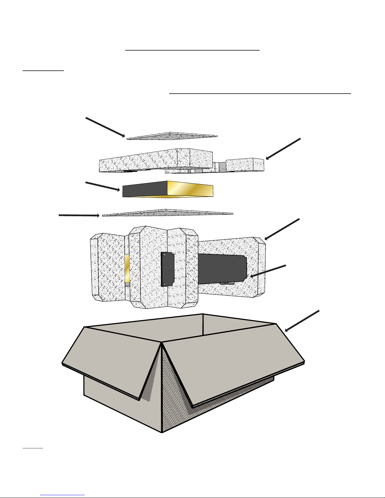
Packaging
This packaging has been designed specically for Chandler Limited equipment. The cardboard carton and rigid foam sur-
rounds provide protection for shipment and storage. Please retain the container and associated materials for future use.
*Note: PSU rigid foam surrounds and sheets are not included for equipment shipped without a power supply unit inside the
equipment container.
CARDBOARD
CARTON
FACEPLATE
CUTOUT
EQUIPMENT
RIGID FOAM
SURROUND
PSU
RIGID FOAM
SURROUND*
SHEET OF
FOAM*
SHEET OF
FOAM*
PSU FRONT
5UM TGMC-120117
000001
Chandler Limited
TG MICROPHONE CASSETTE
INPUT
OUTPUT
COMPRESSOR PRE AMP/EQ
INPUT
OUTPUT
PRE AMP/EQ
PIN 1) 0v
PIN 2) 48v
PIN 3) +28v
PIN 4) -28v
DC POWER LINK
MICROPHONE CASSETTE
TIP- CV
SLEEVE- 0v
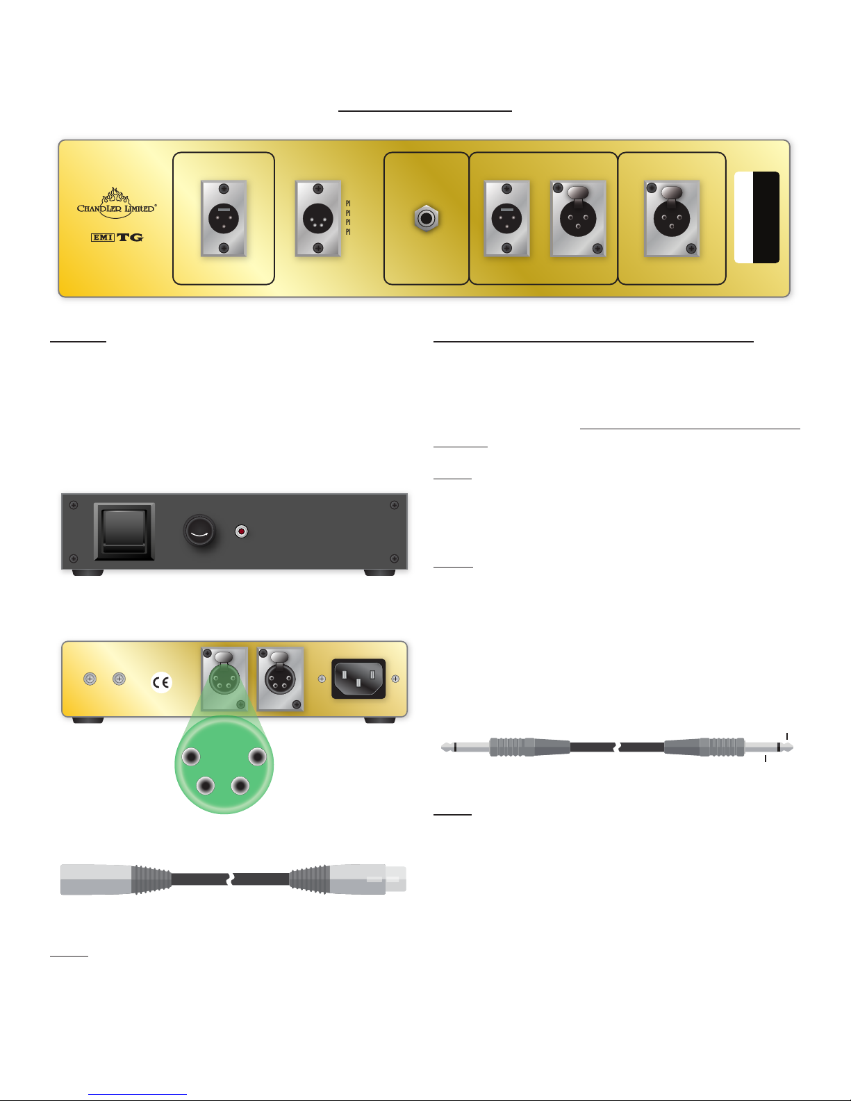
INSTALLATION
Power
The TG Microphone Cassette is powered remotely by the
Chandler Limited PSU-1 power supply, and connected at the,
four pin, DC POWER connector. The PSU-1 is an external
power supply capable of powering two units; the PSU-1 is
purchased separately.
Note: Legacy PSU-1 power supplies featured external
grounding studs. As of mid 2015, grounding studs have been
removed and resistance applied internally.
Audio Input & Output Connections
On the rear panel of the TG Microphone Cassette exists,
two sets of male and female XLR connectors, one pair for
the Pre Amp/EQ section and the other for independent ac-
cess of the Compressor. All audio XLR connectors are wired
pin 2 hot.
Note: To include the TG1 Opto in the audio path, a short
XLR cable must be patched from the Pre Amp/EQ output
XLR to the Compressor input XLR connector.
Link
Provision has been made for stereo linking of two TG1 Opto
compressors, by means of the female ¼” LINK connector lo-
cated on the rear of the unit, and using a standard ¼” cable.
For further notes on operation under linked conditions, re-
view the “Link Operation” section within the “TG1 Opto”
portion of this manual.
Note: Link cable purchased separately.
PSU-1 POWER SUPPLY
FUSE
FUSE 1.5 AMPS 250 V
DC POWER TO EQUIPMENT AC POWER
PIN 1) 0vPIN 4) -28v
PIN 2) 48vPIN 3) +28v
DC POWER CABLE - 4 PIN XLR
LINK -USE STANDARD 1/4” TIP - SLEEVE CABLE CV
0v
6UM TGMC-120117
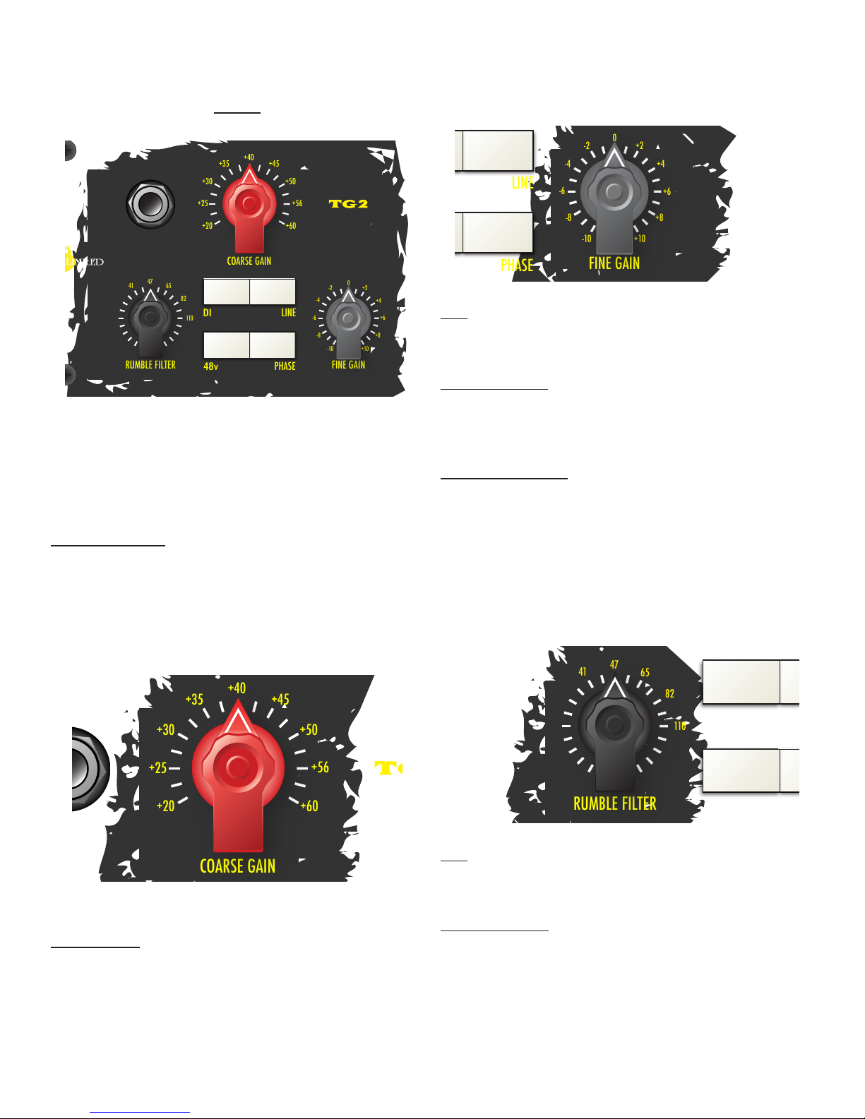
proximate gain required. With Coarse Gain set, then adjust
the Fine Gain control to trim the overall input +/-10 dB as
needed.
Tip: Fine Gain can be used as a great way to dial-in pre-am-
plier coloration; experiment by sweeping across the control
range while listening to the results.
Historical note: The separate switched Coarse Gain and
continuous Fine Gain control-set was how gain staging was
achieved on historic TG console Microphone Cassettes.
Rumble Filter
The Rumble Filter is a low cut facility, providing an Out position
and six frequency settings as follows: 33, 41, 47, 65, 82 and
110 Hz. The Rumble Filter may be fully disengaged from the
pre-amplier by setting its switch to the Out position. When
active, this lter aects source present at the Pre Amp/EQ
input XLR connector. This lter is useful for removing un-
wanted low frequency information from the source.
Tip: More than simply a low cut or high pass, the Rumble
Filter has an eect on the overall signal and can be used as a
powerful tone control.
Historical note: The original Rumble Filter was available
on historic REDD.51 valve consoles, and activated via a plug-
in jumper. The Rumble Filter was xed at 30 Hz, and was
unique in its circuit design.
TG2
The TG2 section of the TG Microphone Cassette is adapted
from Chandler Limited’s TG2 Pre Amp/DI, an historic rec-
reation of the rare EMI TG12428 amplier employed in the
EMI mixing and mastering consoles of the late ‘60s and ‘70s.
Coarse Gain
This rotary switch provides 9 steps of input gain of, 5 dB
each, oering a selectable range between +20 dB and +60
dB. Use the Coarse Gain control to set the initial input gain of
the pre-amplier section.
Fine Gain
This control provides continuous gain trim of +/-10 dB; used
in conjunction with Coarse Gain, a maximum of +70 dB gain
may be achieved.
When gain staging, begin with the Fine Gain control set to
middle (0), and adjust the Coarse Gain control to the ap-
48v
DI
LINE
PHASE
COARSE GAIN
FINE GAINRUMBLE FILTER
-8
-6
-4
-2 0
+2
+4
-10
+6
+8
+10
OUT
33
41 47
65
82
110
®
+30
+35 +40 +45
+50
+25 +56
+20 +60
48v
DI
LINE
PHASE
COARSE GAIN
FINE GAIN
RUMBLE FILTER
-8
-6
-4
-2 0
+2
+4
-10
+6
+8
+10
OUT
33
41 47
65
82
110
®
+30
+35 +40 +45
+50
+25 +56
+20 +60
48v
DI
LINE
PHASE
COARSE GAIN
FINE GAINRUMBLE FILTER
-8
-6
-4
-2 0
+2
+4
-10
+6
+8
+10
OUT
33
41 47
65
82
110
®
+30
+35 +40 +45
+50
+25 +56
+20 +60
48v
DI
LINE
PHASE
COARSE GAIN
RUMBLE FILTER
OUT
33
41 47
65
82
110
®

7UM TGMC-120117
Utility Cluster
Within the TG2 section, exists a cluster of utility push-button
switches labeled as follows: DI, LINE, 48v, and PHASE.
DI
Provision is made for accommodation of instrument level sig-
nals by means of a direct injection facility or DI.
Engaging the DI facility is achieved by setting the push-button
switch labeled DI to the inward position, this allows the Pre
Amp/EQ section to accept instrument level signal via the ¼”
input connector, which is located on the front panel.
When using the DI facility, the output signal will be available
from the Pre Amp/EQ section output XLR connector, which
is located on the rear of the unit.
Note: Instrument level is not the same as line level signal.
Tip: Enabling the DI facility decouples the Pre Amp/EQ sec-
tion’s input XLR, therefore creating a handy mute feature.
Line
The Pre Amp/EQ section is capable of accepting line level
signal.
To accommodate line level signal into the Pre Amp/EQ sec-
tion, rst set the push-button switch labeled Line to the in-
ward position, then apply line level source to the Pre Amp/EQ
input XLR connector, which is located on the rear of the unit.
Tip: Sending line level source into the Pre Amp/EQ section
is a great way to further process material by adding the rich
harmonic texture available from this historic circuit; use a pair
of TG Microphone Cassettes on the mix bus!
48v
Provision is made for 48 volts phantom powering of con-
denser microphones, should they require it. Phantom power
may be enabled by setting the push-button switch labeled 48v
to the inward position, use only for microphones that require
it.
Warning: Only engage or disengage phantom power while a
microphone is connected to the Pre Amp/EQ section of the
cassette. Disconnecting a microphone while phantom power
is on may cause damage to equipment downstream. Never
use phantom power with ribbon microphones. Do not en-
able phantom power when a line level device is connected at
the Pre Amp/EQ input XLR connector.
Phase
The push-button switch labeled Phase, when set to the in-
ward position, transposes the Pre Amp/EQ section input
XLR leads, therefore reversing polarity of the incoming signal
by 180º. This facility may be useful in multi-microphone sce-
narios, when a microphone is not ideally placed, a cable is
wired incorrectly, or source material is out of phase.
48v
DI
LINE
PHASE
COARSE GAIN
FINE GAINRUMBLE FILTER
-8
-6
-4
-2 0
+2
+4
-10
+6
+8
+10
OUT
33
41 47
65
82
110
®
+30
+35 +40 +45
+50
+25 +56
+20 +60
8UM TGMC-120117
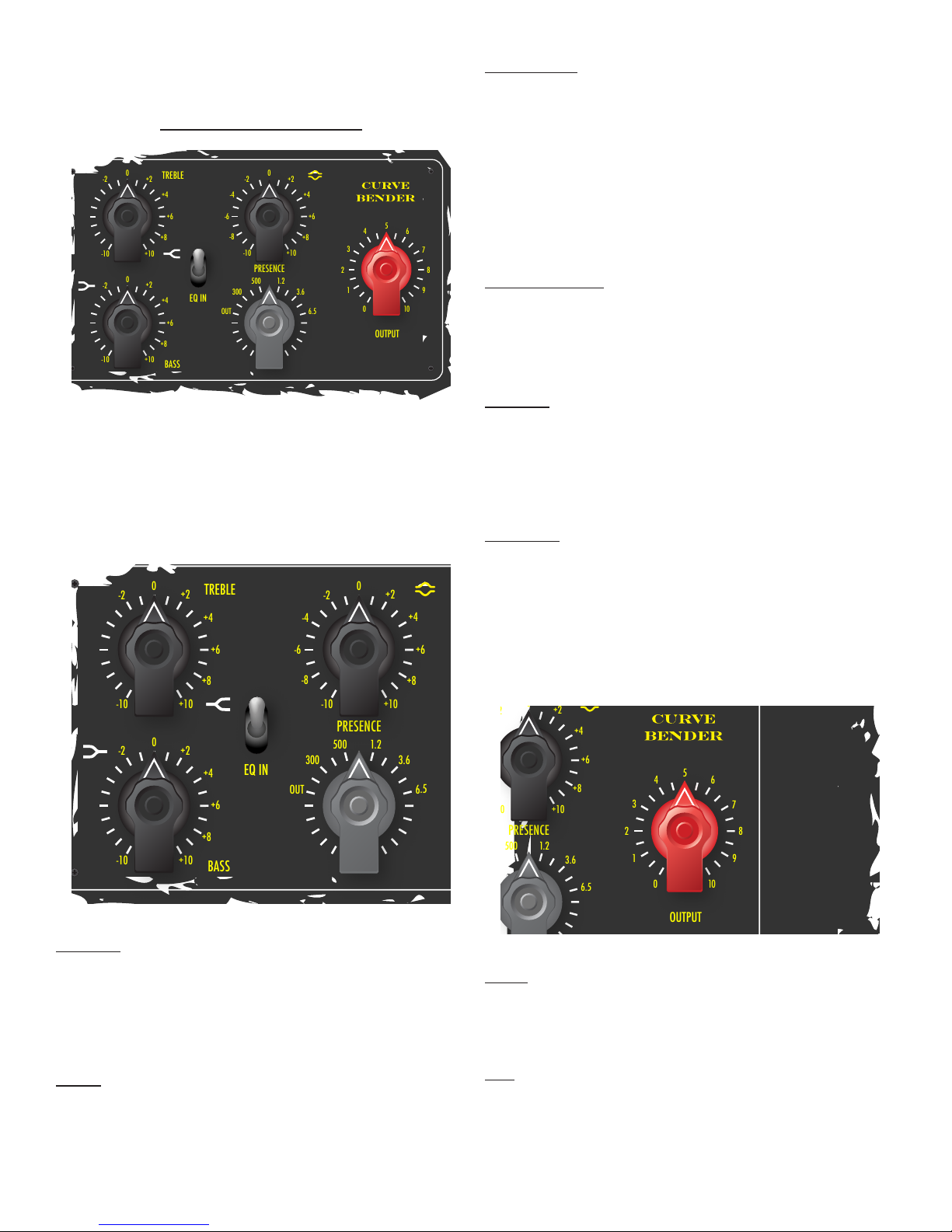
CURVE BENDER
The Curve Bender section of the TG Microphone Cassette is
an adaption of Chandler Limited’s acclaimed EMI TG12345
Curve Bender EQ, itself a greatly expanded recreation of the
EMI TG12345 mixing console’s channel equalizers of the late
‘60s and ‘70s.
Treble
This shelving type EQ control is continuous, allowing for
boost or cut of up to +/-10 dB, at a xed frequency of 8.1
kHz.
Bass
This shelving type EQ control is continuous, allowing for
boost or cut of up to +/-10 dB, at a xed frequency of 91
Hz.
Presence
The Presence or mid band is a bell type EQ, and has two con-
trols: boost or cut and frequency selection. The upper con-
trol is continuous, allowing for +/-10 dB boost or cut at the
frequency selected by lower switch. The available presence
frequencies are as follows: 300, 500, 1.2, 3.6 and 6.5 kHz.
The Presence or mid band can be bypassed independently
apart from the Treble and Bass controls by means of setting
the frequency selection switch to the Out position.
Historical note: 500, 1.2 and 6.5 kHz were frequencies
originally available on the Microphone, Group and Main Cas-
settes of the historic EMI TG12345 desks; the boost or cut
control was a rotary switch.
EQ In
The toggle switch labeled EQ IN, when positioned downward,
inserts the Curve Bender into the audio path; conversely, in
the upward position, the equalizer section is bypassed.
Output
The Output control is continuous, acting as a fader would on
a mixing console. Use this control to trim the overall output
level of the Pre Amp/EQ section to a recording device, con-
verter or interface, external equipment, or to regulate level
sent into the TG1 Opto compressor when patched as part
of the cassette chain.
Note: When setting Pre Amp/EQ section input gain, begin
with the Output control set fully clockwise (10) for unity level,
adjust anticlockwise as needed so as not to clip the targeted
device’s input.
Tip: If extra coloration or harmonic distortion is desired,
this may be achieved by means of overdriving the Pre Amp/
EQ input stage as follows- begin with the Output control low-
er, adjust Coarse Gain considerably higher, and tune Fine Gain
to satisfaction.
OUTPUT
TREBLE
PRESENCE
BASS
EQ IN
564
3
2
1
0
7
8
9
10
-8
-6
-4
-2 0
+2
+4
-10
+6
+8
+10
-8
-6
-4
-2 0
+2
+4
-10
+6
+8
+10
-8
-6
-4
-2 0
+2
+4
-10
+6
+8
+10
300
500 1.2
3.6
6.5
OUT
OUTPUT
TREBLE
PRESENCE
BASS
EQ IN
564
3
2
1
0
7
8
9
10
-8
-6
-4
-2 0
+2
+4
-10
+6
+8
+10
-8
-6
-4
-2 0
+2
+4
-10
+6
+8
+10
-8
-6
-4
-2 0
+2
+4
-10
+6
+8
+10
300
500 1.2
3.6
6.5
OUT
OUTPUT
PRESENCE
564
3
2
1
0
7
8
9
10
-8
-6
-4
-2
0
+2
+4
-10
+6
+8
+10
300
500 1.2
3.6
6.5
OUT

9UM TGMC-120117
BYPASS
SHARP
ATTACK RELEASE
HOLD
ROUNDED
OUTPUT
IN
1
2
3
4
567
8
9
10
11 1
2
3
4
567
8
9
10
11
1
2
3
4
567
8
9
10
11
-10
-9
-8
-7
-6 -5 -4
-3
-2
-1
0
OPTO
KNEE
+12
+8
+4
0
+16
Gain
Reduction
TG1 OPTO
It is little known that EMI technical engineers experimented
with opto detection in their compression circuits. The TG1
Opto is an opto adaptation of Chandler Limited’s TG1 Lim-
iter, a recreation of the limiters found in the historic EMI
TG12345 recording consoles and TG12410 transfer desks of
the late ‘60s and ‘70s.
Historically referred to as a level back-o system, in a modern
context, the TG1 Opto compressor should be considered a
dynamic range reducer, that is- it attenuates transient peaks
while simultaneously amplifying quieter signals.
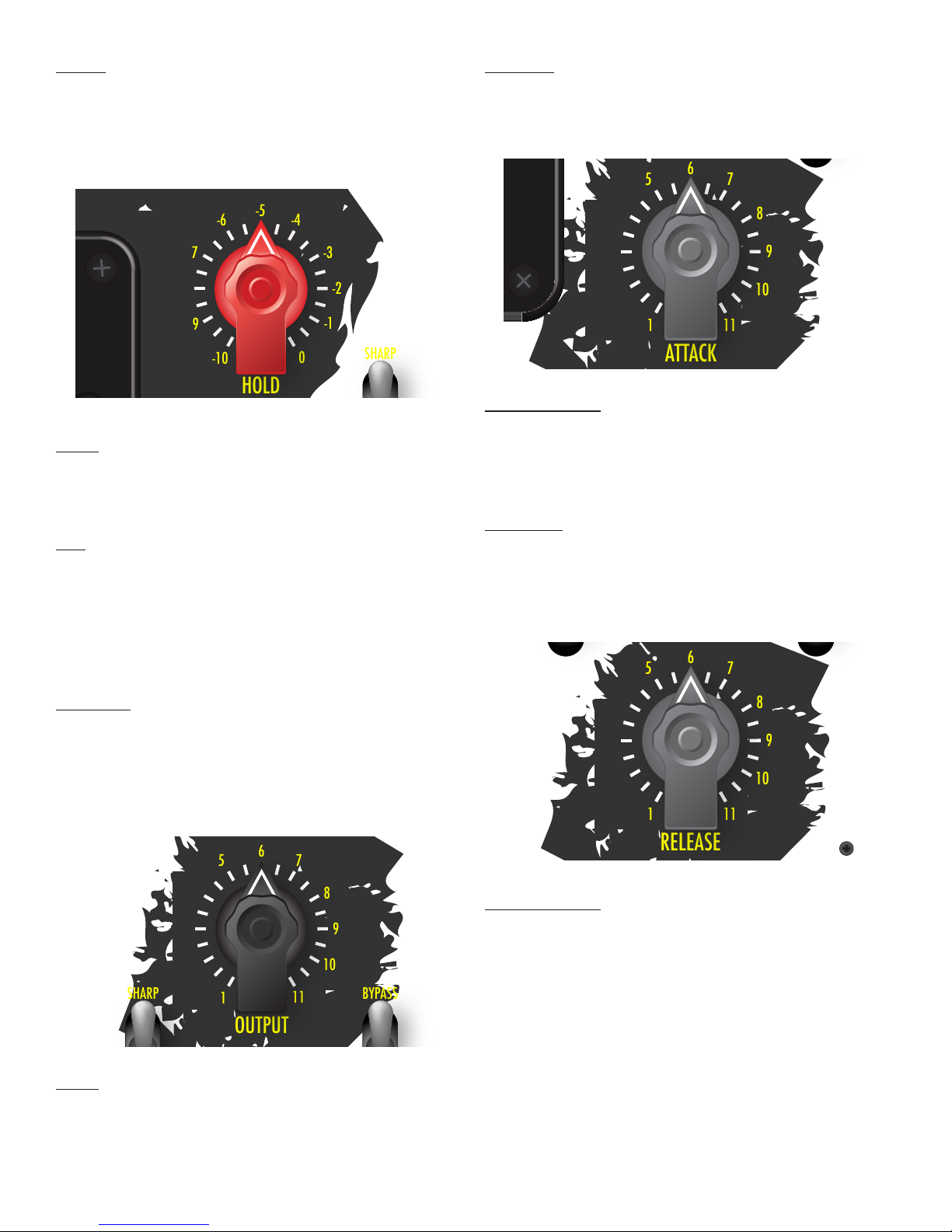
Important Notes on Use
A unique feature of this compressor is the inactive state gain
level - when at rest between compression cycles – as indi-
cated on the Gain Reduction meter when in bypass, can be
preset by means of the Hold control. An important benet
of this moveable resting state is, a better signal/noise ratio
can be realized.
The key towards optimal employment of the TG1 Opto
compressor is, understanding the Gain Reduction meter and
Hold control, without signal present.
The meter scale range begins below 0 and extends to +20 at
the end of the red region.
The degree of compression available is relative to the posi-
tion of the meter needle from the top of the scale and cal-
culated as the dierence thereof: +20 - X needle position = Y
compression.
For example, with the compressor in bypass, positioning the
meter needle by means of the Hold control to +16 on the
scale, will provide up to +4 dB of compression.
Adjusting the Hold control anticlockwise, and placing the me-
ter needle at 0on the scale will provide up to +20 dB of
available compression.
Note: Placing the needle below meter 0will allow maximum
possible reduction and set the inactive state gain to its high-
est level.
Tip: Positioning of the needle between +8 and +12 on the
meter scale, can be a great starting point for most sources.
SHARP
ATTACK
HOLD
ROUNDED
1
2
3
4
567
8
9
10
11
-10
-9
-8
-7
-6 -5 -4
-3
-2
-1
0
OPTO
KNEE
+12
+8
+4
0
+16
Gain
Reduction
MOVEABLE
RESTING STATE
SHARP
ATTACK
HOLD
ROUNDED
1
2
3
4
567
8
9
10
11
-10
-9
-8
-7
-6 -5 -4
-3
-2
-1
0
OPTO
KNEE
+12
+8
+4
0
+16
Gain
Reduction
HOLD PLACED
AT METER 0
UP TO +20 dB
COMPRESSION
SHARP
ATTACK
HOLD
ROUNDED
1
2
3
4
567
8
9
10
11
-10
-9
-8
-7
-6 -5 -4
-3
-2
-1
0
OPTO
KNEE
+12
+8
+4
0
+16
Gain
Reduction
HOLD PLACED AT
METER +16
UP TO +4 dB
COMPRESSION
10UM TGMC-120117
Attack
This is a continuous control and is used to set the speed at
which compression is onset.
Historical note: EMI limiters including the: RS114 tube lim-
iter, RS124 Compressor, RS168 Zener prototype, TG12345
recording console limiters, and TG12410 transfer desk limit-
ers had xed attack times.
Release
This is a continuous control and is used to set the recovery
time from compressed conditions to the inactive state gain
level.
Historical note: EMI limiters including the: RS114 tube lim-
iter, RS124 Compressor, RS168 Zener prototype, TG12345
recording console limiters, and TG12410 transfer desk limit-
ers had six xed recovery (release) times.
Hold
The Hold control is continuous and used to set the desired
degree of compression, a setting of 0is least and -10 is maxi-
mum potential reduction.
Note: The Hold control works independently of level ap-
plied to the compressor, i.e. regardless of where the meter
needle is placed, the hotter the input signal into the TG1
Opto is, the greater the rate of compression be.
Tip: To cope with inconsistent peak level programme, set
the Hold control fully anticlockwise (-10), and send lower lev-
el signal into the compressor, gradually increase the source
until the desired amount of compression is achieved; adjust
the TG1 Opto Output control — described in the next sec-
tion — to make up any gain lost.
Output
Provision is made for makeup gain by means of the compres-
sor’s Output control. This control is continuous and used to
return compressed programme to level; anticlockwise rota-
tion is less makeup gain.
Note: The more compressed programme is, the louder the
processed material may appear, thus necessitating reduction
of the compressor’s Output control.
ATTACK
ROUNDED
1
2
3
4
567
8
9
10
11
+12
+8
+4
0
+16
Gain
Reduction
BYPASS
SHARP
RELEASE
ROUNDED IN
1
2
3
4
567
8
9
10
11
111
KNEE
SHARP
ATTACK
HOLD
ROUNDED
1
2
3
4
567
8
9
10
11
-10
-9
-8
-7
-6 -5 -4
-3
-2
-1
0
OPTO
KNEE
+12
+8
+4
0
+16
Gain
Reduction
BYPASS
SHARP
ROUNDED
OUTPUT
IN
1
2
3
4
567
8
9
10
11
KNEE

11UM TGMC-120117
Bypass
When the TG1 Opto’s Bypass switch is set downward to IN,
the compressor is active, conversely, when positioned up-
ward, it is removed from the audio path.
Note: For the TG1 Opto to be active in the TG Microphone
Cassette signal chain, it must be physically patched at the rear
of the unit, using a short female to male XLR cable (wired pin
2 hot), and connected from the Pre Amp/EQ output XLR to
the Compressor input XLR connector.
Link Operation
When linked to a second TG1 Opto compressor using a
standard ¼” cable via the ¼” Link connector at the rear of
the unit, the linked units are controlled by whichever of the
two control voltages is instantaneously the greater.
Under linked conditions, each compressor’s control set will
be managed independently.
Link connector is wired: Tip – CV, Sleeve – 0v.
Note: When using the TG1 Opto independently of a sec-
ond unit or in mono, be sure to remove any link cable as to
not cause undesired inuence of one another.
Knee
The TG1 Opto provides two compression knee types: Sharp
and Rounded.
Sharp knee
Sharp is equivalent to limit mode on the TG1 and Zener Lim-
iters, and is considered hard. When the Knee switch is set to
Sharp, compression will be full ratio.
Tip: Sharp knees are often employed to control transient
peaks, while increasing overall programme level.
Historical note: On historic EMI TG limiters, Limit mode
was intended to mimic the curve of the studio’s Fairchild 660
units.
Rounded knee
Rounded is a soft type knee. The traditional soft knee is one
in which when triggered, onset of the compression ratio is
gradual; however, the soft knee implementation on the TG1
Opto functions independently from ratio.
Tip: Rounded or soft knees are great in scenarios where
compression is required to be less obvious, such as vocals
and other melodic source.
BYPASS
SHARP
ATTACK RELEASE
HOLD
ROUNDED
OUTPUT
IN
1
2
3
4
567
8
9
10
11 1
2
3
4
567
8
9
10
11
1
2
3
4
567
8
9
10
11
-10
-9
-8
-7
-6 -5 -4
-3
-2
-1
0
OPTO
KNEE
+12
+8
+4
0
+16
Gain
Reduction
BYPASS
SHARP
ATTACK RELEASE
HOLD
ROUNDED
OUTPUT
IN
1
2
3
4
567
8
9
10
11 1
2
3
4
567
8
9
10
11
1
2
3
4
567
8
9
10
11
-10
-9
-8
-7
-6 -5 -4
-3
-2
-1
0
OPTO
KNEE
+12
+8
+4
0
+16
Gain
Reduction
000001
Chandler Limited
TG MICROPHONE CASSETTE
INPUT
OUTPUT
COMPRESSOR PRE AMP/EQ
INPUT
OUTPUT
PRE AMP/EQ
PIN 1) 0v
PIN 2) 48v
PIN 3) +28v
PIN 4) -28v
DC POWER
LINK
MICROPHONE CASSETTE
TIP- CV
SLEEVE- 0v

12UM TGMC-120117
SERVICE
United States
Prior to sending in equipment for repair, please contact our
shop at the number below. We will assist you in trouble-
shooting, and if needed, we will issue an RMA# to return the
equipment for service.
Send Repairs To:
Chandler Limited, Inc.
Attention: Repairs
222 S. Cherry St.
PO Box 38 (if sending via the postal service)
Shell Rock IA 50670
Phone: (319) 885-4200
Email: [email protected]
International
Repair of Chandler Limited products purchased, outside of
the United States, is provided by local or regional authorized
Chandler Limited distributors. To obtain service or repairs,
please contact your local dealer or regional distributor for
further instruction.
Visit chandlerlimited.com for a list of authorized International
Distributors.
CE CERTIFICATION
Chandler Limited declares under its sole responsibility that all
products manufactured by them are in compliance with Elec-
tromagnetic Compatibility (EMC) Directive 2014/30/EU;
Standards: EN55103-1:2009+A1:2012; EN55103-2:2009;
EN55013:2013 and Low Voltage Directive (LVD) 2014/35/
EU; Standards: EN60065:2002+A1:2006+A11:2008+A2:20
10+A12:2011.

13UM TGMC-120117
PRODUCT LIMITED WARRANTY
During the rst year from the date of the original purchase, this product is warranted to be free from defects in materials and
workmanship under normal use, service and maintenance. This warranty applies to the original purchaser and is subject to
the following terms and conditions:
What Is Covered: The product’s components as originally installed by the manufacturer that are defective in materials or
workmanship under normal use, service and maintenance.
What Is Not Covered By This Warranty: This warranty does not extend to or cover:
1. Any defect due to the negligence of others; failure to install, operate or maintain the product properly; unreasonable use;
accidents; alteration; use of unauthorized or non-standardized parts; acts of God; theft; vandalism; electrical malfunctions (i.e.,
resulting from power surges, shorted or overloaded circuits, etc.), use of any power source other than supplied by manufacturer;
repair by anyone other than an authorized Chandler Limited representative; or damage resulting from improper packing or
mishandling by a shipper.
2. Normal wear and tear of parts.
3. Shipping, handling, packaging and delivery costs of the product.
Who Is Covered: The original purchaser.
Repair During The First Year: During the rst year, all defective product components that are covered by this Limited
Warranty will be repaired free of charge including parts and labor. The purchaser will pay shipping costs AND a $35 handling
fee per unit.
WhatYou Must Do for Warranty Service (in the United States): If you live in the United States and your product
was purchased through a U.S. Dealer, please contact your dealer OR call 319-885-4200 or e-mail support@chandlerlimited.
com.
WhatYou Must Do for Warranty Service (outside of the United States): For warranty service if you live outside
of the United States, please contact the dealer where you purchased the product.
Any products returned to Chandler Limited for repair should include: (1) complete description of the problem; (2) name,
address, phone number, fax number, and/or e-mail address; (3) receipt of original purchase; (4) power supply and all acces-
sories and cables. The purchaser is responsible for the shipping costs to and from Chandler Limited. Chandler Limited is
not responsible for damage resulting from improper packing and/or mishandling by a shipper.
If sent by UPS or Federal Express, ship to: Chandler Limited, 222 South Cherry Street, Shell Rock IA 50670
If sent by Postal Service, ship to: Chandler Limited, PO Box 38, Shell Rock IA 50670
The foregoing expresses Chandler Limited’s obligations and liabilities with respect to the quality of the product, its compo-
nents and accessories. All other warranties, express or implied, including the warranties of merchantability or tness for a
particular purpose are disclaimed. Chandler Limited shall not be liable for the loss or use of the product, its components and
accessories, inconvenience, loss or any other damages, direct or consequences arising out of the use of, or inability to use the
product or its components or damages resulting from or attributable to defects in the products or its components. No one
other than Chandler Limited has authority to extend or modify the terms of this limited warranty in any manner whatsoever.

14UM TGMC-120117
DISCLAIMER OF WARRANTY
EXCEPT FOR THE FOREGOING WARRANTIES, CHANDLER LIMITED HEREBY DISCLAIMS AND EXCLUDES ALL
OTHER WARRANTIES, EXPRESS OR IMPLIED, INCLUDING, BUT NOT LIMITED TO ANY AND/OR ALL IMPLIED
WARRANTIES OF MERCHANTABILITY, FITNESS FOR A PARTICULAR PURPOSE AND/OR ANY WARRANTY WITH
REGARD TO ANY CLAIM OF INFRINGEMENT THAT MAY BE PROVIDED IN SECTION 2-312(3) OF THE UNIFORM
COMMERCIAL CODE AND/OR IN ANY OTHER COMPARABLE STATE STATUTE.
LIMITATION OF LIABILITY
THE LIABILITY OF CHANDLER LIMITED, IF ANY, AND PURCHASER’S SOLE AND EXCLUSIVE REMEDY FOR DAM-
AGES FOR ANY CLAIM OF ANY KIND WHATSOEVER, REGARDLESS OF THE LEGAL THEORY AND WHETHER
ARISING IN TORT OR CONTRACT, SHALL NOT BE GREATER THAN THE ACTUAL PURCHASE PRICE OF THE
PRODUCT WITH RESPECT TO WHICH SUCH CLAIM IS MADE. IN NO EVENT SHALL CHANDLER LIMITED BE
LIABLE TO PURCHASER FOR ANY SPECIAL, INDIRECT, INCIDENTAL, OR CONSEQUENTIAL DAMAGES OF ANY
KIND INCLUDING, BUT NOT LIMITED TO, COMPENSATION, REIMBURSEMENT OR DAMAGES ON ACCOUNT OF
THE LOSS OF PRESENT OR PROSPECTIVE PROFITS OR FOR ANY OTHER REASON WHATSOEVER.
Table of contents
Other Chandler Limited Music Mixer manuals


Popular Music Mixer manuals by other brands


Behringer
Behringer Eurorack MX2642A user manual

Peavey
Peavey UMA 35T II Specifications

Alesis
Alesis MultiMix12FX Quick start owner's manual

Behringer
Behringer Eurodesk SL2442FX-Pro user manual

Gemini
Gemini Platinum PS-727 instruction manual

Studiomaster
Studiomaster Professional DJX 825 instruction manual