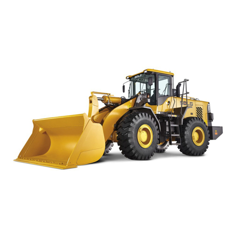
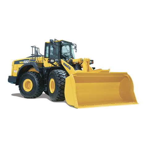
Changlin Company 957H User manual

Preface
This instruction book briefly introduces the structure, performance, operation, and maintenance of
the 957H-type loader, as a reference for drivers, maintenance personnel and relevant technical
management personnel.
As to detail instruction for mating power, please refer to the instruction book of the diesel
manufacturer.
957H type wheel load are continuously improved. Individual content in this instruction may be
slightly different with delivered product; the customer is kindly advised to pay attention to during
application. In case spare parts are necessary for order, please write drawing number, name and
quantity clearly according to parts category and inform ex-work number, ex-work year and month,
type of engine of whole machine order to avoid delivering parts by mistake and affecting
maintenance work of customer.
We truly hope users will propose your opinions to the errors and shortages of this instruction book,
and to the quality of our products, and inform us at any time, so that we can further improve our
products and better serve our uses.
This product measures are up to the Q/CHL01.015-2012 standards wheel loader.
Changlin Company Ltd.
Changlin Company Limited
Add: No.898 West Huang He Road, Xinbei District, Changzhou City, Jiangsu Province
Zip:213136
Website: www.changlin.com.cn
Rest Day: Saturday and Sunday
Customer Service Hotline:4008600710
After-sales service:
Tel: 0519-86781012 86760000(domestic)
Fax: 0159-86751597(domestic)
Tel: 0086-519-86781288 0086-519-86752400(export)
Fax: 0086-519-86781537(export)
Supplier of the Company’s Accessories:
Tel: 0519-86781017 86753324 86754849 86755924(domestic)
Fax: 0519-86752938(domestic)
Tel: 0086-519-86781535(export)
Fax: 0086-519-86781533(export)

Changlin Co., Ltd Environmental Protection Initiatives
Dear users,
Thank you for the Changlin products. Changlin Company Ltd. has passed through the ISO14001 Environment
Management System Authentication on June 7, 2002. Changlin Company Ltd. became the first green
manufacturing enterprise passing through the authentication in the China construction machinery industry. In
order to reduce the impact of the products on the surrounding environment as far as possible and better serve you,
we sincerely ask you and supervise our maintenance personnel to strictly observe the following regulations during
the use and maintenance process:
I. During the use process of the product, when the product has the abnormal noise, excessive tail gas emission,
continuous soot emission, excessive oil consumption, vehicle-use oil leakage and other abnormal phenomena, you
should immediately stop operating or contact our maintenance personnel. The roller shall be stared after check and
troubleshooting. Strictly prohibit the faulted roller to operate. The trouble operation will make the trouble
aggravated so that not only is it difficult to maintain to induce the unnecessary economic loss, but also the
resource waste as well as local air and soil pollution are caused.
II. When the product is maintained, and the vehicle fuel, lubricating oil and hydraulic oil are required to be
drained, please collect the waste oil with the oil receiver. Don’t drain the oil onto the ground directly. The replaced
wasted parts and components shall be classified for collection according to the material. The steel wasted parts
can be recycled, and shall be delivered to the recycling station to treat. The rubber parts and the plastic parts can
not be recycled, and shall be delivered to the local hazardous waste treatment center for recovery processing.
Don’t dispose them to pollute the environment.
Protecting the environment is to protect our homeland; maintaining the ecological environment is to maintain our
life. If the entire earth is regarded as the trash can, will our homeland be the pure land? When the green mountains
and ground, blue sky and water on the earth disappear gradually, will we leave our descendants what kind of
living environment? Never sacrifice the environment to develop the economy. We have the duty and responsibility
to transform the nature and protect the environment, and have ability and confidence to conquer the nature and
improve the environment, but have no right to destroy the ecology and environment. Do not do evil things though
they may be insignificant. Do not give up good things though they may be minor matters. For the protection
environment, everyone shall do everything no matter how it is small.
Changlin Company Ltd., Changzhou, China

Content
Fig. 0-1 Diagram of 957H Transmission System................................................................................................1
Fig. 0-2 957H Overall Size of Loader with bucket.............................................................................................2
I. Application and Characteristics.................................................................................................................3
II. Main Technical Performance and Parameters..........................................................................................4
III. Operating Devices and Meters....................................................................................................................8
IV. Operation of Loader..................................................................................................................................15
(I) Safety Operation Rule:................................................................................................................... 15
(II) Term of Trial Operation................................................................................................................. 16
(III) Driving of Loader:......................................................................................................................... 17
V. Lubrication.................................................................................................................................................23
(I) Notice for Feeding the Lubricant:.................................................................................................. 23
(II) Lubricating Location and Feeding Periodic Chart......................................................................... 23
VI. Interval Technical Maintenance...............................................................................................................28
(I) Daily Technical Maintenance: ....................................................................................................... 28
(II) Weekly Technical Maintenance:.................................................................................................... 28
(III) Every Month Technical Maintenance............................................................................................ 28
(IV) Every Season Technical Maintenance............................................................................................ 29
(V) Semiannually Technical Maintenance ........................................................................................... 29
(VI) Annually Technical maintenance................................................................................................... 29
VII. Structure, Adjustment and Maintenance of Main Components............................................................30
(I) Engine System:.............................................................................................................................. 30
(II) Hydraulic Torque Converter and its Hydraulic Circuit System..................................................... 30
(III) Transmission.................................................................................................................................. 32
(IV) Drive Axle...................................................................................................................................... 39
(V) Steering System ............................................................................................................................. 40
(VI) Brake System................................................................................................................................. 45
(VII) Operating Device and its Hydraulic System.................................................................................. 50
(VIII) Electricity System.......................................................................................................................... 53
(IX) Air-condition system...................................................................................................................... 56
VIII. General Fault and Elimination.................................................................................................................59
IX. Transportation and Storage......................................................................................................................64

1
轮胎23.5-25
前桥
手制动
Z12
Z10
Z9
Z11
Z4
Z8
Z7
Z3
Z2
变速油泵
CBGj1045
Z6
变速箱
Z1 JHP2080S
工作泵
转向泵
发动机
变矩器
后桥
JHP2080S
制动系统
Fig. 0-1 Diagram of 957H Transmission System
Working pump
JHP2080S
Engine
Rear Axle
Gearbox
Torque Converter
Rearward Forward
Hand brake
Front Axle
Gear Pump
CBGJ1045
Brake System
Tire 23.5-25
Steering Pump
JHP2080S
II-Gear III-Gear
I-Gear

2
Fig. 0-2 957H Overall Size of Loader with bucket

3
I. Application and Characteristics
1. Application:
Model 957H Loader is a kind of middle-and-large-sized, multi-purposed and high efficient engineering machinery
equipped with operating units, such as grab, bucket, fork, etc. It is widely applied for loading and unloading log,
shoveling, loading and unloading sand, earth, coal and short-distance transportation in construction engineering,
road construction and road maintenance and repair, and the operations such as earth moving, land leveling,
craning, traction, etc. and applied in the mine, factory, railway station, wharf, freight yard, warehouse, etc.
2. Characteristics:
Model 957H Loader, with front-end loading, four-wheel driven, articulated frame and hydraulic transmission, has
the following characteristics:
1. With famous engine, power reserve, it has a good operation performance and long service-life.
2. With hydrodynamic machinery transmission, double-axle driving, wheel reduction, it has a stable and reliable
transmission system.
3. With balloon, wide and off-road pattern tire, it has the strong adhesive force to ground, less specific pressure,
high cross-country ability and grade ability. It can operate under bad ground conditions.
4. Hinged frame and hydraulic-operated steering, small turning radius, flexible operation, safety and reliability,
compact structure and convenient maintenance.
5. With dual-pipeline and gas-oil disk brake, it has a strong retarding force and is easy for dismounting and
mounting.
6. With the newly-designed Z-type counter-rotation connection rod, single rocker arm and high-pivoted
operating device, it has a strong shoveling force and a high efficiency.
7. The operating device, equipped with guide control and hydraulic control, operates flexibly.
8. Spacious and bright fully closed cab with wide sight, shock reduction performance of seat is good, seating is
comfortable.
9. The appearance of the whole machine applies design with own intellectual property patent, which complies
with international tide, the appearance of the whole machine is beauty and coordinative.

4
II. Main Technical Performance and Parameters
1. Technical Performance
Rated loading capacity 5 t
Rated bucket cubic content 2.2-4.5 m3
Minimum claming diameter of grab (general grab) 350mm
Maximum loading height: Grab (slope angle 46o) 3063 mm
Bucket (slope angle 45o) 3100 mm
Loading distance at maximum loading height: Grab 1433 mm
Bucket 1150 mm
Boom lifting time 5.6s
Boom lowering time 3.7s
Front titling time for bucket or grab (no-load) 1.7s
Speed Forward Backward
First gear 0-6.8km/h 0-8.km/h
Second gear 0-10.8 km/h 0-14.3km/h
Third gear 0-32km/h 0-34.1km/h
Minimum radium of turn (front wheel outside) 6098 mm
(bucket outside) 6775 mm
Maximum gradeability 30o
Peak traction 150kN
Maximum excavating force 165kN
2. Main Size and Weight
Length of loader (from grab put on ground) 8155mm
(from bucket put on ground) 8130mm(C6121)8270 mm(CUMMINS)
Width of loader (from outside of wheel) 2800mm
Height of loader (from top of cab) 3450mm
Width of bucket 2946mm
Width of grab 2100mm
Axle-base 3200mm
Wheel tread 2200mm
Minimum clearance from ground (lower hinged point) 450 mm
Center height of traction hook 1200mm
Weight of loader: with full of oil and water and grab 17.0(±5%) t
with full of oil and water and bucket 16.7(±5%) t

5
3. Engine
Manufacturer
CUMMINS ENGINE COMPANY
Shanghai Diesel Engine Co., Ltd
Model
6CTAA8.3-C215
SC11CB220G2B1
Type
Vertical, 4-stroke, direct injection,
turbocharged, air/air intercooler
Vertical, 4-stroke, direct injection,
water cooled, turbocharged,
Number of cylinder -
Diameter × stroke (mm)
6 –114 ×135
6-120.65×152.4
Total piston displacement
(L)
8.3
10.45
Compression ratio
18:1
15:1
Rated rotational speed
(r/min)
2200
2200
Rated power (1 hour
power, kW)
160
162
Maximum torque (N·m)
998
843
Fuel consumption
(g/KW·h)
207
≤235
Starting mode
24V starting
24V starting
Weight (kg)
617
960
Note: 957H may select other engine on basis of performance guarantee of whole machine according to
requirements of different areas and different customers, the customer is kindly advised to refer to engine
instruction with machine.
4. Transmission System
Hydraulic Torque Converter
Type Single-step and single phase three operating wheel
Cooling mode Oil cooling and pressure cycle
Outlet oil pressure 0.245 ~ 0.343 MPa (2.5 ~ 3.5 kgf/cm2)
Transmission gear
Type Cylindrical spur-gear parallel-axis non-clashing gear
Speed oil pump CBGj1045 gear pump (left handed)
Clutch Multiply-disk, oil cooling, pressure cycle
Operating oil pressure of clutch 1.47 ~ 1.86MPa (15 ~ 19kgf.cm2)
Front and RearAxle Driving
Type Spiral bevel gear, first-reduction
Hunting angle of rear axle 11ofor upward and downward
Hub Reduction Gear
Type Cylindrical spur gear planetary driving
Wheel and tire (same for four wheels)
Tire size 23.5 - 25 - 16PR

6
Tire pressure 0.294 ~ 0.314 MPa (3.0 ~ 3.2 kgf/cm2)
Rim 19.50/2.5 - 25 (TB)
5. Brake System
Foot brake
Type Dual-pipeline, gas-oil, caliper-disk four-wheel brake
Retarding disk diameter 466mm
Brake gas pressure 0.6 ~ 0.75 MPa
Hand Brake
Type Pneumatic internal expansion shoe type
6. Steering System
Model
957H
Type
Hinged frame, loading sensor, full-hydraulic steering
Hydraulic steering gear displacement
1000 ml/r
Model of steering pump
JHP2080S(C6121), CBGj2080/2040-XF(CUMMINS)
Steering pump - cylinder diameter x stroke
2 - 90
435 mm
Maximum operating pressure
16 Mpa
Steering angle of hinged frame
about 38o
7. Hydraulic System
Model
957H
Type
Proportion guide control
Model of operating oil pump
JHP3160
Lifting cylinder
2 - 160 x 810 mm
Bucket-turning cylinder
1 - 180 x 528 mm
Working pressure
18 MPa
Reversal valve
7130-B109 hydraulic control multiple-circuit reversal valve
8. Electric System
System voltage 24V
Storage battery 115E41R two-series
Earth-grounding Negative
Model of generator Silicon rectifier generator
Power 1000W
Power 8.2 kW (CUMMINS) 7.5kW(C6121)

7
9. Refueling Capacity
Crankshaft box of engine 20L((CUMMINS) 42L(C6121)
Fuel chamber 250L
Hydraulic torque converter and gear box 42L
Hydraulic oil tank 180L
Front and rear axle driving 2 ×18L
Hub reduction gear 4 ×3.0L
Brake system 4 ×1.5L
10. Air-condition system
The system applies cooling system and warm wind facilities
Type of air conditioner: BKG08G
Cooling capacity: 4300W
Type of compressor: TL-508 or SD5H14
Heating capacity: 7500W
Voltage: 24V.DC
Electric power consumption: <360W
Manufacturer: Bogesizhong (Changzhou) Air-condition System Co., Ltd

8
III. Operating Devices and Meters
Before driving, it is necessary to know the location and function of each operating device, meter and indicating
light. The arrangement of devices and meters in cab is shown in Fig. 3 - 1. The operator falls into the habit of
watching the instrument board always in operation and discovers any abnormal condition on time.
Fig. 3 –1 Operation equipments and instruments in cab
1. Travel brake pedal
2. Forward and backward
handle
3. Voltmeter
4. Engine oil pressure
meter
5. Fuel level meter
6. Left turning indication lamp
7. Low brake pressure
indication lamp
8. Charging indication
lamp
9. Low engine oil pressure
indication lamp
10. Low transmission oil
pressure indication lamp
11. Parking brake indication
lamp
12. Headlight indication
lamp
13. Level shifting indication
lamp
14. Emergency brake indication
lamp
15. Right turning indication
lamp
16. Torque converter oil
temperature meter
17. Engine water pressure
meter
18. Brake air pressure meter
19. Hour meter
20. Horn button
21. Steering lamp switch
22. Oil valve pedal
23. Guiding operation level
24. Parking brake
indication lamp
25. Instrument lamp switch
26. Headlight lamp switch
27. Rear lamp switch
28. Working lamp switch
29. Fan switch
30. Wiper switch
31. Rear wiper switch
32. Parking brake handle
33. Gear disengagement
selection handle

9
1. Instrument and indication lamp:
Function and application scope of each instrument are listed as following:
(1) Voltmeter
Indicate voltage of system. Power supply voltage which is input into instrument is used to
display system voltage, indication scope: 16~36Vdc.
(2) Hour meter:
Indicate accumulated working times of engine. Liquid crystal screen digital display. Display
scope: 0.0 ~ 99999.9H; automatically memorize local data in case of power off. Working
hours meter will accumulate on current accumulated data when engine operates; hopper sign
flashes; accumulate 0.1 hour every 6 minutes. Working hour meter stop accumulating when
engine doesn’t operate, display total accumulated hours, hopper sign doesn’t flash.
(3) Engine oil pressure meter:
Indicate engine oil pressure of engine. Display with resistance value of pressure sensor
placed on engine oil system of engine. Indication scope: 0MPa~1MPa; ≤0.1MPa is red zone,
>0.1 is white zone. When needle enters into red zone, low engine oil pressure alarm
indication lamp is lit; in case engine operates, the instrument will send out alarm sound.
(4) Torque converter oil temperature meter
Indicate oil temperature of torque converter. Display through inspection of resistance value of
temperature sensor placed in transmission gear. Total rotation angle of needle is 270°,
stepping angle is 2°, indication scope: 60℃(C)~120℃(H); ≥110℃is red zone, <110℃is
white zone. When the needle enters into red zone and engine operates, the instrument will
send out alarm sound. When temperature exceeds normal scope and approximates to
maximum value, change transmission handle to lower level, reduce rotation speed of engine
or stop operation until oil temperature is reduced to normal scope.
(5) Engine water pressure meter:
Indicate cooling water temperature of engine. Display through inspection of resistance value
of cooling water circulation system placed in engine. Total rotation angle of needle is 270°,
stepping angle is 2°, indication scope: 60℃(C)~140℃(H); ≥110℃is red zone, <110℃is
white zone. When the needle enters into red zone and engine operates, the instrument will
send out alarm sound. When the needle enters into red zone and the instrument sends out
alarm sound, immediately stop operation and driving, engine operates at idle speed and stop
after water temperature is dropped down. Check whether there is fault in engine system under
low water temperature. Then carry out normal operation and travel after fault is excluded.
(6) Brake air pressure meter
Display through inspection of resistance value of pressure sensor placed on air pressure
system. Total rotation angle of needle is 270°, stepping angle is 2°, indication scope: 0MPa~
1MPa; ≤0.45MPa is red zone, >0.45 is white zone. When the needle enters into red zone,
low brake air pressure alarm indication lamp is lit, when engine operates, the instrument will
send out alarm sound.

10
(7) Fuel level meter
Indicate fuel oil level. Display through inspection of resistance value of fuel sensor placed in
fuel tank. Total rotation angle of needle is 270°, stepping angle is 2°, indication scope: 0(E)~
1(F); ≤1/8 is red zone, >1/8 is white zone.
2. Indication lamp and switch:
(1) Charging indication lamp
If the indication lamp is lit, it means charging the battery.
(2) Low transmission oil pressure indication lamp:
When oil pressure of the transmission gear is less than 1.2MPa, this indication lamp is lit.
(3) Left and right turning indication lamp (green):
When the switch handle is pushed forward, the left turning indication lamp and front and rear
turning indication lamp at left side continue flash;
When the switch handle is drawn backward, the right turning indication lamp and front and
rear turning indication lamp at right side continue flash;
(4) Parking brake indication lamp:
When hand brake handle is pressed down, this indication lamp is lit.
(5) Service brake indication lamp:
!When the brake pedal is stepped down, the indication lamp is lit.
(6) High beam indication lamp:
When the high beam lamp is switched on, this indication lamp is lit.
(7) Low engine oil pressure alarm indication lamp is lit:
When engine oil pressure of the engine is in red alarm zone, this indication lamp is lit.
(8) Level shifting indication lamp:
When the level selection handle is on upper position, this indication lamp isn’t lit, it means
power of the transmission is cut off when the brake pedal is stepped down; when the level
selection handle is pressed down, this indication lamp is lit, it means power of the
transmission isn’t cut off when the brake pedal is stepped down.
Note: Unless operate or travel on slope, and the level selection handle is selected to be pressed down, the
level shifting indication lamp is lit; otherwise the level selection handle must be placed on upper position
and the level shifting indication lamp isn’t lit, then carry out normal operation or travel.

11
(9) Emergency brake indication lamp: Standby.
(10) Low brake pressure indication lamp:
When this indication lamp is lit, it means brake air pressure is lower than 0.45MPa, don’t
travel and operate. When this indication lamp isn’t lit, it means brake air pressure rise up
0.45MPa, then travel and carry out operation.
(11) Starting switch of electronic door key:
Plug the key into the switch of the electronic door as figure 3 –2, turn clockwise the key to connection position,
then turn clockwise to starting position, connect the starting motor and start up the diesel engine. When weather is
cold, turn the starting switch anti-clockwise to pre-heat position, then start after air incoming for preheating.
Fig. 3-2 Key preheat starting switch
Note: When it is turn to starting and turn to connection, the key switch is self-locked; it can’t be directly
turn to starting position. It can be started again only after it is turn to stop in order to protect starter
against damage caused by repeated starting.
Each starting time shall not exceed 10 seconds. Interval time between two starting shall not be
shorter than 1 minute.
(12) Switch components
Front Lamp Switch
When the switch is pushed in the middle, the front lamp lights with near light;
When the switch is pushed down, the front lamp lights with far light.
Rear Lamp Switch
When the switch is pushed in the middle, the rear lamp lights with near light;
When the switch is pushed down, the rear lamp lights with far light.
Work Lamp Switch
Breakage
Secondary heating
Connection
Starting up

12
When the switch is pushed down, the top working lamp in the driving cab lights.
Instrument lamp Switch
When the switch is pushed down, all instrument lamps as well as front and rear width lamps
light.
Fan Switch
When the switch is in middle position, fan will run in low speed.
When the switch is in lower position, fan will run in high speed.
Wiper Switch
When the switch is pushed in the middle, the rain brush runs at low speed;
When the switch is pushed down, the rain brush runs at high speed;
When the switch is pushed up, the rain brush resets and stops running.
(13) Rear wiper switch
When the switch is placed at middle position, the wiper operates at low speed;
When the switch is placed at lower position, the wiper operates at high speed;
When the switch is placed at upper position, the wiper resets and stops operating.
(14) General switch of power supply (it is located below left protection door of engine, which isn’t indicated
in figure)
When the switch is turn left, the power supply is on; when the switch is turn right, the power supply is off.
Note: Power supply shall be switch off when it doesn’t operate for long time or stops for maintenance.
(15) Trumpet Button
When the button in the middle of the steering wheel is pushed down, the trumpet sounds.
(16) Steering Light Switch
This handle is used to operate the steering signal lamp.
①Turn to left: push up the operating lever;
②Turn to right: push down the operate lever.
Note: When the steering wheel returns to the middle, the steering signal does not be
removed, you should let the operating lever reset.
(17) Mp3 player
Play mp3.

13
(18) Safety pipe case
When the fuse is replaced, the type shall be same as that of original fuse (it isn’t indicated in figure 3.1-1).
(19) Air-condition system:
The cab is equipped with air-condition system. When strong cooling is required, the switch of the air conditioner
shall be turn to cooling position, the cooling degree can be suitably adjusted. The switch of air conditioner can be
turn to warm air position during cold winter time in order to improve temperature of the cab. It greatly improves
the working environment. The cab is equipped with the fan. When the switch of the fan is drawn out, the fan
immediately operates.
3. Control Lever and Pedal:
进、退操纵手柄
档位操纵手柄
Ⅲ挡 退
Ⅱ挡 空
Ⅰ挡 进
Fig. 3-3 Gear shift lever
(1) Gear shift lever: (See Fig. 3 - 3)
Steering lever pushed forward, move forward
Steering lever pulled backward, move backward
Steering lever in middle position, stop
Gear shift lever in I, the first gear
Gear shift lever in II, the second gear
Gear shift lever in III, the third gear
(2) Accelerator pedal:
It is used for control the fuel-supply for engine. When the pedal is loosened, engine is under idle operation and
when the pedal is depressed, the revolution of engine is increased with fuel-supply increasing.
(3) Retarding pedal:
When the pedal is depressed, the loader is retarded, valve is cut off and the clutch is left off the gear box to cut off
the transmission system.At this time, rail braking light is lit.
(4) Hand brake control lever:
It is used for parking brake. Pulling up is to brake and pushing down is to loosen. Before don’t forget to loose the
hand brake control lever.
Level operation handle
Forward and backward operation handle
I-gear up
II-gear neutral
III-gear down

14
(5) Control lever of operating device:
Bucket control lever.
Rearward: If the lever is push to the left from neutral position, it will rest at this place till the
bucket reach to the position that is set in advance, then the lever reverts the neutral
position. ②Position in right figure.
Rest: The bucket keeps in a certain place. ①Position in right figure.
Forward: Unloading. ③Position in right figure.
Booms control lever.
Lifting: If this lever is put from rest position to up, it will rest till the booms reach to the
position that is set, and then the lever reverts the neutral position. ①Position
in right figure.
Neutral:The booms keep in a certain place. ②Position in right figure.
Lowering:Boom drops down. ③Position in right figure.
Floating: The booms move freely by force. ④Position in right figure.
Forward
Lift
Lower
Rearward

15
IV. Operation of Loader
(I) Safety Operation Rule:
1. It is not permitted for unqualified driver to drive the loader. The driving trainee drives the loader under the
instruction of the qualified driver.
2. Before driving, the driver should understand the performance, structural characteristics, operation essentials
and maintenance and service method as well as the necessary traffic regulations.
3. Before starting, vehicle examination and preparation shall be made according to the stipulations. Once the
problems are discovered, it shall not be operated until the failure is removed.
4. Before starting and operating, observe whether or not there are any persons and barriers around the loader
and horn the signals.
5. When the engine operates, it is not permitted that any persons stand or walk between front tire and rear tire,
in the front of frame, on the boom, bucket and grab and no permission for any persons stand or walk under
the operating device.
6. It is necessary to avoid maintenance and service under the operation of engine. If it is required, it should be
operated by the qualified driver.
7. In running, it is not permitted for any persons to go up and down from the loader. No person is permitted to
sit on the loader except in cab.
8. In running, improper high speed and turning rapidly should be avoided.
9. In going downhill, it is not permitted to drive without gear on to prevent the engine from extinction. The
revolution of engine should be kept in minimum operating speed. Especially in steep slope and abrupt
turning, it shall run with low speed gear and in 1000 rpm and keep the steering system in good performance.
The extinction shall result in steering fault and accident.
10. When passing through bridge, the driver shall pay attention to the bearing capability of the bridge.
11. In operating, it loads the materials with bucket inserting in first gear and without shocking in high-speed and
inertia force.
12. In shifting forward and backward gear, the brake pedal is depressed at first and then the steering control
lever is pulled.
13. The materials are evenly loaded with grab and bucket. It is necessary to avoid the material not balanced in
grab and bucket. It is not permitted for grab or bucket lifting high position to run. If there are any obstacles in
the way and it is required to lift in high position, the driver shall drive carefully and lower the boom about 40
cm from the ground after passing the obstacles.
14. When the gas pressure is below 0.6 Mpa. (6 kg/m2), it is not permitted to drive the loader.
15. In maintenance and service of engine or electrical system, the mass power switch should be shut-off.
16. Before leaving cab after working off, the bucket and grab should be laid down on the ground with shutting
off engine and switching off power.
17. When opening the cover of heat water tank or cover of hydraulic oil tank, the grooves should be put on with
slowing opening to prevent from burning the people.
18. No smoke is allowed in feeding fuel or maintenance and service.
19. The fuel or oil should be clean in conformity with the stipulated brand and quality standard.
20. In cold winter weather, the loader should be stayed in warm house not in the open air in night to prevent

16
storage battery and parts from damaging. The fuel or oil suitable for winter weather should be used.
21. All damages resulting from operating, driving and maintenance and service not conforming to these
operation regulations shall not be covered in “Three Guarantees – guaranteed repairs, guaranteed returns, and
guaranteed exchanges that factories apply to their products in order to gain the trust of customers.”
22. The other safety regulations refer to “Safety Manual”.
(II) Term of Trial Operation
Before the new loader brings into formal operation, one-hundred term of trial operation shall be carried out. It is
very important for the service life of loader. During the period of trial operation term, the loader shall be carefully
driven and the loading shall be gradually increased. With run-in wear of parts and components in engine and
several replacements of fuel and oil, the loader shall bring its full technical performance into play and lengthen the
service life as longer as possible.
The trial-operation term is also suitable for the loader after overhaul.
i. Preparation:
(1) Check if every part of the machine is installed firmly, if bolts and nuts are fixed,if accessories are complete,
and if there it is disabled.
(2) Check that all control levers of instruments are fixed and fastened without any damages.
(3) Check that all pipelines and connections for fuel, cooling, brake, steering, torque converter, gearbox,
hydraulic and pneumatic systems are fastened without any damages.
(4) Check that the belt of engine fan is properly tensioned.
(5) Check that the pressure of tires conform to the stipulated requirements.
(6) Check that electrolytic of storage battery is fully enough and connections are fastened.
(7) Check that the quantity and brand of lubricant, oil, water and fuel are conformity with the stipulations.
(8) Loosen the lock fixed with hinged frame before running.
ⅱ. No-load Trial Operation Term (10 hours)
(1) Place the control levers in neutral position, pull the hand brake and start the engine according to the starting
method. The initial revolution is kept in 600 –750 rpm for five-minute operation and then in 1000 –1200
rpm for ten-minute operation. Check that the indication and sound of meters are normal.
(2) Lift and lower the boom, turn tool and open and close gripper-jaw for 5 –10 times. Turn the steering wheel
for several times. Check that all actions are correct without any abnormal conditions
(3) Loose the hand brake and drive the loader in first-gear, second-gear and third-gear. During the period of
running, smoothly control the operating device and check that there are not any leakage in oil, water and gas,
braking is reliable, steering is flexible and indictor lights and steering signals are normal (Caution:
Revolution of engine doesn’t exceed to 1800 rpm).
(4) After ten-hour no-load running-in, check that all bolts and nuts are fastened, especially for bolts of engine
cylinder head, in-let and exhaust pipe, front and real axles, rim, transmission shaft. The engine oil filter and
fuel filter are cleaned.
ⅲ. 50% Rated Load Trial Operation Term (40 hours):
(1) Operate under loading weight not exceeding 2.5 ton and 1800 rpm.
(2) Smoothly operate lifting and shoveling.

17
(3) Make maintenance and service at regular interval in and after the trial operation term.
(4) Clean filter in hydraulic oil tank, rough filter in transmission system and air clearer.
(5) Replace engine oil and hydraulic torque converter oil.
ⅳ. 75% Rated Load Trial Operation Term (50 hours)
(1) After 50% rated load trial operation term and check that all are normal, the loading is increased to 75% and
revolution to 2200 rpm.
(2) Make maintenance and service at regular interval in the term, after 100-hour operation, the loader shall be
fully checked, all filters and clearer shall be cleaned and the hydraulic oil in hydraulic system of operating
device and lubricants used for front and rear axle and hub reduction gear shall be replaced.
(3) In the trial operation term, if the overheating or other abnormal conditions are discovered, the loader can not
operate until the fault is removed.
(4) The conditions in 100-hour operation should be recorded. If the unqualified parts and components are
discovered and can not be solved, the recorded conditions are submitted to our company.
(5) After 100-hour trial operation, it is confirmed that all assemblies are operated normally and the loader can
bring into normal operation according to the stipulated load.
(III) Driving of Loader
i. Preparation before Driving:
The following items should be checked before driving:
(1) Clean off the oil dirty and soil.
(2) Engine oil surface is within the level of oil dipstick
(3) Loose the drain plugs in fuel pump and fuel filter and make the fuel system discharge with hand pressing
pump.
(4) Feed the radiator cooling water in proper level. When winter weather is below 0℃, it is necessary to feed
warm water or ethylene glycol anti-freeze fluid.
(5) Check fuel tank. If required, feed the enough fuel filtered in full so as to prevent moisture from condensing.
(6) Check oil surface of transmission which shall approximate to upper scale line of oil gauge when the
whole machine starts up.
(7) Check that oil surface in hydraulic oil tank is kept in the top of oil meter. Feed oil with same brand.
(8) Drain out the moisture in air storage reservoir with drain valve and after draining, it should be tightened
again.
☆If water in air storage cylinder is not drained in line with the requirement, the performance of the
entire machine would be reduced or disabled.
(9) Check that tire pressure is normal. If tire pressure is too lower, the load capability is inadequate and tire has a
short service life. If the tire pressure is too high, the vibration of vehicle increases and the center part of tire
wears out rapidly.
(10) Check that all connections are fastened.
(11) Feed the lubricating oil and grease in each lubrication point according to the stipulations shown in the
Lubrication Table.
Table of contents
