Chatoyer KRO - 3000 User manual

KRO - 3000
AUGUST 2006
Prepared for:
WashTec Australia
1, 33 Maddox Street
Alexandria NSW 2015
Sydney, Australia
Prepared by:
Chatoyer Holdings Pty. Ltd.
ABN: 99 080 301 515
www.chatoyer.com.au
BRISBANE OFFICE
14 Parkview Street
Milton QLD 4064
PO Box 2156 Milton QLD 4064
Tel: (07) 3367.3866
Fax: (07) 3367 2886
brisbane@chatoyer.com.au


Operation Manual
KRO3000 Rev2
2
Table of Contents
1.0 Principles of Reverse Osmosis 3
2.0 Pre Treatment 3
3.0 System Configuration 4
3.1 KRO3000 4
3.2 Pre Treatment 4
4.0 Process Description and System Components 5
4.1 General Process 5
4.2 System Components 5
4.2.1 Water Softener 5
4.2.2 Carbon Filter and Cartridge Filters 6
4.2.3 High Pressure Pump 6
4.2.4 RO Membrane Housing 6
4.2.5 RO Membrane 6
4.2.6 Conductivity Monitor 6
4.2.7 Reject Control Valve 6
4.2.8 Recycle Control valve 7
4.2.9 Flush Solenoid Valve 7
4.2.10 Rotameters 7
4.2.11 Pressure Gauges 7
4.2.12 Low Pressure Switch 7
4.2.13 Float Switch 7
4.2.14 Pressure Reducing Valve 7
5.0 Installation Guide 7
6.0 Description of Operation 8
6.1 Starting Up the Unit 8
6.2 Shutting Down the Unit 9
7.0 Maintenance 9
8.0 Trouble Shooting 10
9.0 Servicing 11
10.0 Expected Values 11
Appendices 12
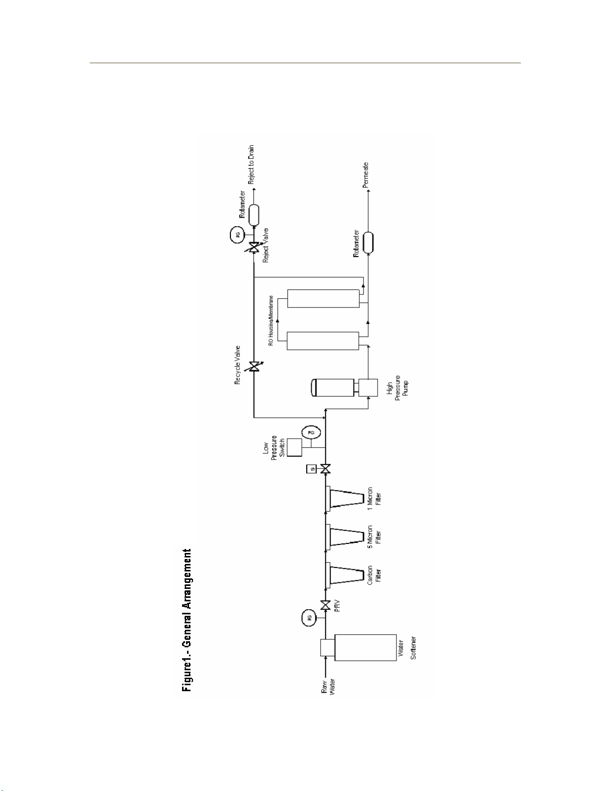
Appendix I - General Arrangement 13
Appendix II - Electrical Diagram 14
Appendix III – Performa Softener Manual 15

Operation Manual
KRO3000 Rev2
3
Please read this operating manual prior to use and store in a safe place for referral at a
later date.
1.0 Principles of Reverse Osmosis
The heart of the system is a semi-permeable membrane that will allow small molecules to
pass through, such as water (H2O) and reject larger molecules such as sodium Chloride
(NaCl). At atmospheric pressure, if a membrane separates two of different solution strengths,
ions from the stronger solution tend to flow into the weaker solution until equilibrium is
attained.
As the name suggests, “Reverse Osmosis,” reverses this natural tendency by exerting an
“Osmotic pressure” on the membrane.
Now the concentrated side of the membrane forces the smaller water molecules through the
membrane to the permeate collection manifold. The concentrated water becomes more
concentrated and the diluted water becomes more pure.
The most important aspect of reverse osmosis operation is to ensure the raw feed is correctly
treated to prevent fouling and possible irreversible damage to the reverse osmosis
membrane.
2.0 Pre Treatment
Rarely, in fact, almost never is water suitable for direct entry to the membrane housing.
Table 1 shows a number of contaminants present in raw water capable of causing a
permanent damage to the membranes. Please note these are the main contaminants.
However, other salts or metals may be encountered and would require a specific treatment.
Table 1.- Main Contaminants
Contaminant Membrane Effect Treatment Options
Chlorine (Cl) Oxidation
Membrane Destruction
Sodium Metabisulphite (SMBS) dosing/
Activated Carbon Filter
Chloramines Oxidation
Membrane Destruction
Sodium Metabisulphite (SMBS) dosing/
Activated Carbon Filter
Iron (Fe) Fouling Aerating/chlorination (followed by
dechlorination)
Ozone(followed by de-ozonation)
Manganese Fouling Manganese Greensand Filtration
Calcium
Bicarbonate
Scaling Base Exchange Water Softening
Proprietary Antiscalants
Magnesium
Sulphate
Scaling Base Exchange Water Softening
Proprietary Antiscalants
Biological
Activity
Biological Fouling Aerating/chlorination (followed by
dechlorination)
Ozone(followed by de-ozonation)
Suspended
Solids
Colloidal Fouling Coagulation and or Filtration

Operation Manual
KRO3000 Rev2
4
Table 2.- KRO Models
Item Model
800GPD 1500GPD 3000GPD(1) 6000GPD
Minimum Feed Flow Capacity 270 LPH 500 LPH 1000LPH 2000LPH
Minimum Feed Pressure 280 kPa
Water Temperature 5 45 °C
pH 6.5 – 9
Total Hardness Nominally 17ppm as CaCO3
Turbidity < 1 NTU’s
Silt Density Index SDI < 5
Total Dissolved Solids (TDS) < 1000ppm
Iron (Fe) < 0.1ppm
Manganese (Mn) < 0.05ppm
Dissolved Oxygen < 0.1ppm
Organics < 1ppm
(1) This manual is applicable for model KRO3000
3.0 System Configuration
3.1 The KRO3000 is completed with the following items:
RO membrane and Stainless Steel membrane Housing.
Stainless Steel frame.
Carbon / 5-Micron &1 Micron cartridge filters.
Horizontal Booster Pump.
Low-pressure protection switch.
Solenoid valve.
Permeate, Reject and Recycle Rotameters.
Digital controller.
CM-230 Conductivity meter.
Feed water pressure gauge.
Pre-membrane pressure gauge.
System (reject) pressure gauge.
3.2 Pre Treatment is completed with the following items:
Water Softener complete with automatic valve to control service, backwash and
regeneration cycles.

Operation Manual
KRO3000 Rev2
5
4.0 Process Description and System Components
4.1 General Process
This is to be read in conjunction with the General Arrangement drawing (Figure 1).
The raw water is pre treated before entering the KRO3000. The first stage of pre treatment is a
water softener which eliminates hardness to prevent scaling problems.
The softened water flows to a carbon filter to remove the chlorine which is detrimental to RO
membranes. Following the carbon filter the water passes through a 5 and 1 micron filters
arrangement to remove suspended material.
Filtered water is pumped via a high pressure (boost) pump through the RO housing, containing
the membrane. Permeate (treated water) is sent to a break tank and the Reject (brine) is sent to
the drain.
A Recycle line is also provided, this line goes from the reject line to the pump suction line. The
purpose of the recycle is to create a hydraulic equilibrium, correct recovery rate and system
pressure.
The system is completed with an inlet solenoid valve. This valve automatically turns off the water
supply between the feed water and the membrane. A level control inside the tank sends a signal
to the valve to close when the tank is full. Once the level in the tank is low, the level control sends
another signal to the solenoid valve to permit the flow of raw water into the system. Every time
the valve opens/closes the system will start/stop automatically.
A Flush solenoid valve is also provided with the unit. This valve is under the control of a timer.
Periodically the valve opens to flush the membrane at low pressure. This extends the periods
between membrane cleans.
4.2 System Components
4.2.1 Water Softener
The water is Hard when Calcium and Magnesium are dissolved in it. These salts precipitate out of
the water causing scaling problems. To prevent this situation the water is pre treated using a
water softener.
Raw water flows through a media (small plastic beads or chemical zeolite) covered in sodium
ions. The calcium and magnesium ions are replaced with sodium ions. As sodium does not
precipitate out of the water, the scaling problem is eliminated.
However, the media is exhausted after certain amount of water has been treated. This is because
no more sodium ions are available to swap places with calcium and magnesium. Consequently,
the media needs to be regenerated.
The regeneration process is very simple. The media is soaked with a Sodium Chloride (brine
tank) solution. The sodium ions change places with the calcium and magnesium trapped in the
media. In this way the media is being regenerated and is ready to exchange the sodium ions
again. The remaining brine plus all of the calcium and magnesium is flushed through a drain.
The regeneration cycles on the KRO3000 systems are programmed based on the hardness of
the inlet water.

Operation Manual
KRO3000 Rev2
6
Caution: THE SALT USED FOR REGENERATION OF THE WATER SOFTENER MUST BE
“CROWN HG WATER SOFTENER SALT”. NO OTHER SALT CAN BE USE FOR
REGENERATION.
4.2.2 Carbon Filter & Cartridge Filters
The carbon filter is designed to remove the chlorine from the water. Cartridge filters are designed
to remove suspended material greater than 5-Micron @ 1-Micron prior to the pre treated water
flows into the membrane. This protects the membrane from significant colloidal contamination.
The cartridges should be renewed every 4 months, as minimum. If the raw water is significantly
polluted then the cartridges should be changed in a shorter period of time.
Caution: It is EXTREMELY important to renew the cartridges. Mainly the carbon filter. If
any trace of chlorine goes into the housing, the membrane will be permanently damaged.
4.2.3 High-Pressure Pump
High-pressure pump is one of the key components, to boost the pressure for correct membrane
operating conditions.
4.2.4 RO Membrane Housing
RO membrane housing is to guarantee the RO membrane can work under the conditions of
normal pressure and seal arrangement.
Caution: The operator should apply silicon grease on the “Y’ type plastic ring in order to
ensure proper sealing of the membrane brine seal.
4.2.5 RO Membrane
RO membrane is the key component of the RO main unit and has a determinative effect on the
quantity and quality of water produced. The RO membrane utilizes pressure-energy to separate
larger contaminant molecules from the body of water.
For a given Temperature, Pressure and feed Total Dissolved Solids (TDS), if the quantity of water
produced decreases by 10%, please consult your supplier of the unit.
4.2.6 Conductivity Monitor
The function of conductivity monitor is to measure conductivity condition of the permeate water.
Caution: Please do not clean with strong acid and strong alkali to prevent the electrodes
from being damaged.
4.2.7 Reject Control Valve
The main function of the reject valve is to adjust the reject flow from the membrane. Adjust the
reject valve to attain the correct recovery rate and systems pressure in conjunction with the
recycle valve.
Caution: Please do not turn off the reject valve. The high pressure in the membrane
housing may cause irreversible damage to membrane and/or housing.

Operation Manual
KRO3000 Rev2
7
4.2.8 Recycle Control Valve
The main function of the recycle valve is to adjust the flow from the membrane brine port to the
booster pump suction. Adjust the recycle valve to attain the correct recovery rate and systems
pressure in conjunction with the reject valve.
Caution: Please do not turn off the recycle valve. The high pressure in the membrane
housing may cause irreversible damage to membrane and/or housing.
4.2.9 Flush Solenoid Valve
The flush solenoid valve is under the control of a timer. Periodically the valve opens to flush the
membrane at low pressure. This tends to extended the periods between membrane cleans.
4.2.10 Rotameters
Rotameters are provided to indicate the permeate and reject flow rates
4.2.11 Pressure Gauges
Pressure gauges are provided to monitor operating conditions and facilitate the adjustment of the
recycle and reject valves
4.2.12 Low-Pressure Switch
Low-pressure switch is a safety device that in conjunction with the controller shuts down the unit
in the event of low feed pressure.
4.2.13 Float Switch
.A facility is provided to connect an external float switch in the permeate storage tank. When the
circuit is broken between the, “HIGH-LEVEL,” contacts (no volt) the unit automatically stops. The
unit will remain on standby until the level in the tank drops, remaking the circuit.
4.2.14 Pressure Reducing Valve (PRV)
If no break tank and set pump is available for the raw water supply, then a PRV is provided to
guarantee the correct operating feed pressure going into the system. The PRV also protects the
unit from over pressure situations that may cause damage to the equipments.
The feed pressure must be between 250 to 500kPa.
5.0 Installation Guide
Installation Environment and Technical Requirements
5.1 The operator should install the unit in a covered dry place, shielded from the elements to
protect the electrical components and equipments generally from damage and
premature deterioration.
5.2 Sufficient room should be allowed to conveniently operate and service the unit.
5.3 Consideration should be given to any additional pre treatment that may be required prior
to operating the unit.

Operation Manual
KRO3000 Rev2
8
5.4 The influent water temperature must be between 5 and 45°C.
5.5 Permeate and reject lines must be no smaller than the unit outlet size. In the event of
long pipe runs, increasing the pipe size diameter may be necessary.
Ask for our suppliers engineer to consult on any item above that may be of concern.
Caution: Please check the power supply is the correct voltage and current rating. Refer to
the circuit diagram of RO main unit.
6.0 Description of Operation
6.1 Starting Up the Unit
6.1.1 Open the reject valve and recycle valves fully
6.1.2 Open feed water valve
6.1.3 Turn on the power supply.
6.1.4 Depress the RO Pump button
6.1.5 If the HIGH contacts are closed, after a short time delay the inlet valve will open
and allow water to enter the system. This first stage will expel air to prevent
damage to the membrane(s) [telescoping].
6.1.6 The flush valve will be open (the high reject flow rate will not be visible in the
reject rotameter).
6.1.7 After a few minutes the flush valve will close. The reject flow rate should be at the
maximum rate in the rotameter.
6.1.8 Slowly close in the reject valve and the recycle valve to attain the correct
operating pressures and reject flow rates*.
The correct operating conditions depend on:
Feed Temperature
Feed water analysis
Calculated recovery
Pre-treatment conditions
Caution: Do not start or operate the unit with either the recycle or reject valve closed.
Severe damage to the membrane and other component may result.
Caution: Do not operate the system at excessive pressures. If over a period:
The permeate conductivity increases by 15% or
The permeate production decrease by 10% or
The HP pump discharge pressure increases by 15%
The influent water quality has changed or membranes require periodic cleaning. Do not increase
the membrane pressure beyond 115% or permanent damage to the membranes may result.
When using the unit for the first time, discard the first hour of production to drain. This will rinse
out any preservative chemical used in membrane storage.

Operation Manual
KRO3000 Rev2
9
6.2 Shutting Down the Unit
6.2.1 Normally the unit will stop when the permeate tank if full. However, should the
unit be required to be stopped manually depress the RO PUMP button.
6.2.2 If the unit is not to be used for a period longer than 48 hours please consult your
supplier for advice regarding preservation of the membrane (membrane fouling
will occur if the unit is idle for long periods).
7.0 Maintenance
7.1 The membranes should be cleaned about every six months or whenever performance
diminishes as set out above.
7.2 Please consult your supplier to arrange cleaning of the membrane(s).
7.3 The filter cartridge should be replaced every four months as minimum.
7.4 Additional pre treatment should be serviced in accordance with the manufacturer’s
recommendations.
7.5 Should any component such as the HP pump not be performing according to
specifications, consult your supplier for servicing.

Operation Manual
KRO3000 Rev2
10
8.0 Trouble Shooting
Table 3.- Trouble Shooting
Symptoms Cause Remedies
Unit will not start •No power
•Insufficient Water
Pressure
•Permeate Tank Full
•Digital Controller
damaged
•Check power supply
•Check inlet valve is
open/ and Check
solenoid valve is
operational/Check
cartridge filter
•Reset float switch
•Service/Replace
HP Pump will not start •Circuit breaker Off
•Overload Tripped
•Pump Motor High
Temperature
•Switch on
•Reset check current
setting
•Allow to cool
HP Pump starts but water
Pressure low
•Flush Valve Open
•Recycle valve fully
open
•Reject valve fully open
•Pump fault
•Pump cavitation
•Wait until flush cycle
completes
•Close valve in
•Close valve in
•Inspect pump
•Bleed air from pump
HP Pump starts but Trips •Motor Overload •Check motor and
pump/Check overload
setting/Check controller
Excessive Membrane
Pressure
•Reject Valve Closed
•Recycle Valve Closed
•Membrane(s) fouled
•Excessive feed
Pressure
•Open
•Open
•Replace/clean
membrane(s)
•Check feed PRV setting
Permeate water quality
poor
•Membrane perforated
by chlorine attack
•Replace carbon
cartridge and
membrane

Operation Manual
KRO3000 Rev2
11
9.0 Servicing
Table 4 shows the basic steps maintenance personnel should follow when servicing a KRO3000
unit. This will allow them to identify if the unit is operating correctly.
Table 4.- Servicing KRO3000
Steps Yes No
1. Check pressure and flow rates against values in table 5.
2. Check brine tank is full (Recommended level 50% of full
capacity).
3. Check that no hard layer of salt has been formed on the
surface of the brine tank.
4. Keep record of the last change of filters
5. If a problem is identified please refer to the Trouble Shooting
section (Section 8.0) or call your supplier of the unit.
Caution: THE SALT USED FOR REGENERATION OF THE WATER SOFTENER MUST BE
“CROWN HG WATER SOFTENER SALT”. NO OTHER SALT CAN BE USE FOR
REGENERATION.
10.0 Expected Values
Table 5 shows the expected flow rates and pressures for KRO3000 unit.
Table 5.- Expected values for KRO3000
Parameter Value
Feed Pressure 30 – 40 psi
RO Pressure 105 – 115 psi
Concentrate Pressure 110 – 120 psi
Permeate Flow 5 – 7 LPM
Recycle Flow 14 – 16 LPM
Concentrate Flow 8 – 10 LPM

Operation Manual
KRO3000 Rev2
12
Appendices
Operation Manual
KRO3000 Rev2
13
Appendix I

Operation Manual
KRO3000 Rev2
14
Appendix II

Operation Manual
KRO3000 Rev2
15
Appendix III

Softener/Filter
Water Control System
Installation, Operation and Maintenance Manual
Autotrol Performa Cv
®™
This system installed by:

1.0 Performa Cv System
1.1 Specifications
1.1.1 Performa Cv Softener
Flow Rates (Valve Only)
Service @ 15 psi (1.03 bar) . . . . . . . . . . . . . . . . . . . . . . . . . . . . . . . . . . . . . . . . . . . . . . . . . . . . . . 25.0 gpm (5.7 m3/h)
Backwash (Softener) @ 25 psi (1.72 bar) drop . . . . . . . . . . . . . . . . . . . . . . . . . . . . . . . . . . . . . . . 20.0 gpm (4.5 m3/h)
Service . . . . . . . . . . . . . . . . . . . . . . . . . . . . . . . . . . . . . . . . . . . . . . . . . . . . . . . . . . . . . . . . . . . . . Cv = 6.5 (Kv = 5.58)
Backwash Softener. . . . . . . . . . . . . . . . . . . . . . . . . . . . . . . . . . . . . . . . . . . . . . . . . . . . . . . . . . . . Cv = 4.0 (Kv = 3.46)
Control Configurations
962 Microprocessor Demand System and 962 Electronic Timeclock
Backwash. . . . . . . . . . . . . . . . . . . . . . . . . . . . . . . . . . . . . . . . . . . . . . . . . . . . . . . . . . . . . . . . . . . . . . .4 to 60 minutes
Brine . . . . . . . . . . . . . . . . . . . . . . . . . . . . . . . . . . . . . . . . . . . . . . . . . . . . . . . . . . . . . . . . . . . .Electronically calculated
Slow rinse. . . . . . . . . . . . . . . . . . . . . . . . . . . . . . . . . . . . . . . . . . . . . . . . . . . . . . . . . . . . . . . . . . . . . .7 to 125 minutes
Fast rinse . . . . . . . . . . . . . . . . . . . . . . . . . . . . . . . . . . . . . . . . . . . . . . . . . . . . . . . . . . . . . . . . . . . . . . .2 to 19 minutes
External Brine Valve Required - Timed Fill
Valve Connections/Dimensions
Tank Thread . . . . . . . . . . . . . . . . . . . . . . . . . . . . . . . . . . . . . . . . . . . . . . . . . . . . . . . . . . . . . . . .2-1/2 inches - 8, male
Inlet/Outlet . . . . . . . . . . . . . . . . . . . . . . . . . . . . . . . . . . . . . . . . . . . . . . . . . . . . . . . . 1-3/4 inches - 12 UNC-2A, male
Drain Line . . . . . . . . . . . . . . . . . . . . . . . . . . . . . . . . . . . . . . . . . . . . . . . . . . . . . . . . . . . . . . . . . . . .3/4-inch NPT, male
Brine Line . . . . . . . . . . . . . . . . . . . . . . . . . . . . . . . . . . . . . . . . . . . . . . . . . . . . . . . . . . . . . . . . . . . . 3/8-inch NPT, male
Distributor Tube O.D. . . . . . . . . . . . . . . . . . . . . . . . . . . . . . . . . . . . . . . . . . . . . . . . . . . . . . . . . . 1.050 inches (27 mm)
Distributor Tube Length . . . . . . . . . . . . . . . . . . . . . . . . . . . . . . 1/2 ± 1/2 inches (13 mm ± 13 mm) above top of tank
Operating
Valve Body . . . . . . . . . . . . . . . . . . . . . . . . . . . . . . . . . . . . . . . . . . . . . . . . . . . . . . . . . . . . . . . . . . . Glass-Filled Noryl*
Rubber Components . . . . . . . . . . . . . . . . . . . . . . . . . . . . . . . . . . . . . . . . . . . . . . . . . . . .Compounded for cold water
Weight (Valve with Control). . . . . . . . . . . . . . . . . . . . . . . . . . . . . . . . . . . . . . . . . . . . . . . . . . . . . . . . . . 4.5 lbs (2.0 kg)
Transformer Output. . . . . . . . . . . . . . . . . . . . . . . . . . . . . . . . . . . . . . . . . . . . . . . . . . . . . . . . . 12 VAC 400 mA (4.6 vA)
Transformer Input . . . . . . . . . . . . . . . . . . . . . . . . . . . . . . . . . . . . . . . . . . . . . . . . . . . . 115V 50/60 Hz, 230V 50/60 Hz
100 V 50/60 Hz
Operating Pressure. . . . . . . . . . . . . . . . . . . . . . . . . . . . . . . . . . . . . . . . . . . . . . . . . . . .20 to 120 psi (1.37 to 8.27 bar)
Canada: 20 to 100 psi (1.37 to 6.89 bar)
Water Temperature . . . . . . . . . . . . . . . . . . . . . . . . . . . . . . . . . . . . . . . . . . . . . . . . . . . . . . . . . 35°to 100°F (2°to 38°C)
Options
Bypass Valve, Model 1265 . . . . . . . . . . . . . . . . . . . . . . . . . . . . . . . . . . . . . . . . . . . . .1-3/4 inches - 12 UNC-2A male
Bypass Fitting Kits:
Copper, Sweat Tube Adapter . . . . . . . . . . . . . . . . . . . . . . . . . . . . . . . . 1-1/4-inch, 1-inch, 3/4-inch, 28-mm, 22-mm
CPVC, Solvent Weld Tube Adapter. . . . . . . . . . . . . . . . . . . . . . . . . . . . . . . . . . . . . . . . . . . . .1-inch, 3/4-inch, 25-mm
Plastic NPT or BSPT Pipe Adapter. . . . . . . . . . . . . . . . . . . . . . . . . . . . . . . . . . . . . . . . . . .1-inch male, 3/4-inch male
Brass NPT or BSPT Pipe Adapter . . . . . . . . . . . . . . . . . . . . . . . . . . . . . . . . . . . . . . . . . . .1-inch male, 3/4-inch male
Flow Meter 962 Control . . . . . . . . . . . . . . . . . . . . . . . . . . . . . . . . . . . . . . . . . . . . . . . . . . . . . 1-inch Autotrol Turbine
*Noryl is a trademark of the General Electric Company.

1.1.2 Performa Cv Filter Specifications
Flow Rates (Valve Only)
Service @ 15 psi (1.03 bar) drop . . . . . . . . . . . . . . . . . . . . . . . . . . . . . . . . . . . . . . . . . . . . . . . . . 25.0 gpm (5.7 m3/h)
Backwash (Filter) @ 25 psi (1.72 bar) drop. . . . . . . . . . . . . . . . . . . . . . . . . . . . . . . . . . . . . . . . . . 25.0 gpm (4.5 m3/h)
Service . . . . . . . . . . . . . . . . . . . . . . . . . . . . . . . . . . . . . . . . . . . . . . . . . . . . . . . . . . . . . . . . . . . . . .Cv = 6.5 (Kv = 5.58)
Backwash Filter . . . . . . . . . . . . . . . . . . . . . . . . . . . . . . . . . . . . . . . . . . . . . . . . . . . . . . . . . . . . . . .Cv = 5.0 (Kv = 5.78)
Control Operation
942F Mechanical Clock Timer - 7 Day or 12 Day
Backwash. . . . . . . . . . . . . . . . . . . . . . . . . . . . . . . . . . . . . . . . . . . . . . . . . . . . . . . . . . . . . . . . . . . . . . . . .8-30 minutes
Fixed Fast Rinse. . . . . . . . . . . . . . . . . . . . . . . . . . . . . . . . . . . . . . . . . . . . . . . . . . . . . . . . . . . . . . . . . . . . . . .9 minutes
962F Microprocessor Demand
Backwash. . . . . . . . . . . . . . . . . . . . . . . . . . . . . . . . . . . . . . . . . . . . . . . . . . . . . . . . . . . . . . . . . . . . . . . 4 to 60 minutes
Fast Rinse. . . . . . . . . . . . . . . . . . . . . . . . . . . . . . . . . . . . . . . . . . . . . . . . . . . . . . . . . . . . . . . . . . . . . . . 2 to 19 minutes
962 FTC Electronic Time Clock
Backwash. . . . . . . . . . . . . . . . . . . . . . . . . . . . . . . . . . . . . . . . . . . . . . . . . . . . . . . . . . . . . . . . . . . . . . . 4 to 60 minutes
Fast Rinse. . . . . . . . . . . . . . . . . . . . . . . . . . . . . . . . . . . . . . . . . . . . . . . . . . . . . . . . . . . . . . . . . . . . . . . 2 to 19 minutes
Interval Regeneration. . . . . . . . . . . . . . . . . . . . . . . . . . . . . . . . . . . . . . . . . . . . . . . . . Day of the Week Regeneration
Valve Connections/Dimensions
Tank Thread . . . . . . . . . . . . . . . . . . . . . . . . . . . . . . . . . . . . . . . . . . . . . . . . . . . . . . . . . . . . . . . .2-1/2 inches - 8, male
Inlet/Outlet . . . . . . . . . . . . . . . . . . . . . . . . . . . . . . . . . . . . . . . . . . . . . . . . . . . . . . . . .1-3/4 inches - 12 UNC-2A, male
Drain Line. . . . . . . . . . . . . . . . . . . . . . . . . . . . . . . . . . . . . . . . . . . . . . . . . . . . . . . . . . . . . . . . . . . . 3/4-inch NPT, male
Brine Line . . . . . . . . . . . . . . . . . . . . . . . . . . . . . . . . . . . . . . . . . . . . . . . . . . . . . . . . . . . . . . . . . . . . 3/8-inch NPT, male
Distributor Tube O.D. . . . . . . . . . . . . . . . . . . . . . . . . . . . . . . . . . . . . . . . . . . . . . . . . . . . . . . . . . 1.050 inches (27 mm)
Distributor Tube Length . . . . . . . . . . . . . . . . . . . . . . . . . . . . . . 1/2 ± 1/2 inches (13 mm ± 13 mm) above top of tank
Operating
Valve Body . . . . . . . . . . . . . . . . . . . . . . . . . . . . . . . . . . . . . . . . . . . . . . . . . . . . . . . . . . . . . . . . . . . . .Glass-filled Noryl
Rubber Components . . . . . . . . . . . . . . . . . . . . . . . . . . . . . . . . . . . . . . . . . . . . . . . . . . . .Compounded for cold water
Weight (Valve with Control). . . . . . . . . . . . . . . . . . . . . . . . . . . . . . . . . . . . . . . . . . . . . . . . . . . . . . . . . . .4.5 lbs (2.0 kg)
Transformer Output . . . . . . . . . . . . . . . . . . . . . . . . . . . . . . . . . . . . . . . . . . . . . . . . . . . . . . . . .12VAC 400 mA (4.6 vA)
Transformer Input. . . . . . . . . . . . . . . . . . . . . . . . . . . . . . . . . . . . . . . . . . . . . . . . . . . . .115V 50/60 Hz, 230V 50/60 Hz
100V 50/60 Hz
Operating Pressure . . . . . . . . . . . . . . . . . . . . . . . . . . . . . . . . . . . . . . . . . . . . . . . . . . .10 to 120 psi (1.37 to 8.27 bar)
Canada: 20 to 100 psi (1.37 to 6.89 bar)
Water Temperature. . . . . . . . . . . . . . . . . . . . . . . . . . . . . . . . . . . . . . . . . . . . . . . . . . . . . . . . .34°to 100°F (1°to 38°C)
Options
Bypass Valve, Model 1265. . . . . . . . . . . . . . . . . . . . . . . . . . . . . . . . . . . . . . . . . . . . 1-3/4 inches - 12 UNC - 2A male
Bypass Inlet/Outlet Fitting Kits:
Copper, Sweat Tube Adapter. . . . . . . . . . . . . . . . . . . . . . . . . . . . . . . . .1-1/4-inch, 1-inch, 3/4-inch, 28-mm, 22-mm
CPVC, Solvent Weld Tube Adapter . . . . . . . . . . . . . . . . . . . . . . . . . . . . . . . . . . . . . . . . . . . . 1-inch, 3/4-inch, 25-mm
Plastic NPT or BSPT Pipe Adapter . . . . . . . . . . . . . . . . . . . . . . . . . . . . . . . . . . . . . . . . . . 1-inch male, 3/4-inch male
Brass NPT or BSPT Pipe Adapter . . . . . . . . . . . . . . . . . . . . . . . . . . . . . . . . . . . . . . . . . . . 1-inch male, 3/4-inch male
Flow Meter 962 Control . . . . . . . . . . . . . . . . . . . . . . . . . . . . . . . . . . . . . . . . . . . . . . . . . . . . 1-inch Autotrol Turbine

1.2 Installation
All plumbing and electrical connections must conform
to local codes.
Inspect unit carefully for carrier shortage or shipping
damage.
Location Selection
1. Thedistancebetween theunitandadrainshouldbe
as short as possible.
2. If it is likely that supplementary water treatment
equipment will be required, make certain adequate
additional space is available.
3. Since salt must be added periodically to the brine
tank, the location should be easily accessible.
4. Do not install any unit closer to a water heater than
a total run of 10 feet (3 m) of piping between the
outlet of the conditioner and the inlet to the heater.
Water heaters can sometimes overheat to the
extent they will transmit heat back down the cold
pipe into the unit control valve.
Hot water can severely damage the conditioner. A
10-foot (3-m) total pipe run, including bends,
elbows, etc., is a reasonable distance to help
prevent this possibility. A positive way to prevent
hot water flowing from heat source to the
conditioner, in the event of a negative pressure
situation, is to install a check valve in the soft
water piping from the conditioner. If a check valve
is installed, make certain the water heating unit
is equipped with a properly rated temperature
and pressure safety relief valve. Also, be
certain that local codes are not violated.
5. Do not locate unit where it or its connections
(including the drain and overflow lines) will ever be
subjected to room temperatures under 34oF (1oC)
or over 120oF (49oC).
6. Do not install unit near acid or acid fumes.
7. The use of resin cleaners in an unvented enclosure
is not recommended.
Water Line Connection
The installation of a bypass valve system is
recommendedtoprovideforoccasionswhenthewater
conditioner must be bypassed for hard water or for
servicing.
The most common bypass systems are the Autotrol
Series 1265 bypass valve (Figure 1.1) and plumbed-in
globe valves (Figure 1.2). Though both are similar in
function, the Autotrol Series 1265 bypass offers
simplicity and ease of operation.
Figure 1.1 - Autotrol Series 1265 Bypass Valve
Figure 1.2 - Typical Globe Valve Bypass System
Drain Line Connection
Note: Standard commercial practices are expressed
here.Local codesmayrequire changesto thefollowing
suggestions.
1. Ideally located, the unit will be above and not more
than 20 feet (6.1 m) from the drain. For such
installations, using an appropriate adapter fitting,
connect 1/2-inch (1.3-cm) plastic tubing to the drain
line connection of the control valve.
2. If the backwash flow rate exceeds 5 gpm
(22.7 Lpm)or if the unitis located more than 20 feet
(6.1 m) from drain, use 3/4-inch (1.9-cm) tubing for
runs up to 40 feet (12.2 m). Also, purchase
appropriatefittingtoconnectthe3/4-inchtubingto
the 3/4-inch NPT drain connection.
3. If the unit is located where the drain line must be
elevated, you may elevate the line up to 6 feet
(1.8 m) providing the run does not exceed
15 feet (4.6 m) and waterpressure at conditioner is
not less than 40 psi (2.76 bar). You may elevate an
additional 2 feet (61 cm) for each additional
10 psi (0.69 bar).
B
Y
P
A
S
S
B
Y
P
A
S
S
B
Y
P
A
S
S
B
Y
P
A
S
S
Not in Bypass In Bypass
Water
Conditioner
In Out
Water
Conditioner
In Out
Water Water
Not in Bypass In Bypass
Water
Conditioner Water
Conditioner
Table of contents
Popular Water Filtration System manuals by other brands


GE
GE Homespring UFC 100 Operation manual

amiad
amiad TEQUATIC PLUS F-75 Installation, operation and maintenance manual

Sullair
Sullair OWS-88 User & service manual

Watts
Watts PWDWUV3 Installation, operation and maintenance manual

OptiPure
OptiPure FX-21 Installation, operation & maintanance manual

Brita
Brita On tap Instructions for use