chatron miiBIO User manual

1
miiBIO
miiBIO
Instruction
manual for
installation of
Biocooler
Smart Solar

2
miiBIOmiiBIO
Instruction
manual for
installation of
Biocooler
Smart Solar

3
BIOCOOLER
Solar Power Installation
Index
1. Introduction Page.3
2. Warnings Page.3
3. System Page. 4
4. Installation Page. 7
5. Connections Page. 9
6. Maintenance Page. 13
7. Faults Page. 14
Annex A – esquema quadro de energia
Annex B – inversor solar
1 - Introduction
To obtain the maximum level of service and sa-
tisfaction of our Solar Biocooler, please read this
manual carefully before installation.
2 - Warnings
Please read the warnings. They are listed for the
protection of people and the product. Neglecting or
ignoring these warnings can result in death or serious
injury and ends with the warranty. The system must be
installed by people with knowledge of electricity.
• The system must be installed and operated only by quali-
fied personnel. Make sure all power sources are turned off
when handling the installation wires.
• Prevent the control equipment from being exposed to di-
rect sunlight or other sources of heat.
• Install a ground system suitable for safety and protection
against lightning. A well-sized ground system can reduce
the chances of severe damage.
• Follow the recommendations for power cables. Undersized
cables may cause fan malfunction or even cable melting.
• To test, avoid joining wires to create spark. Use a multime-
ter to check the voltages.
• There are potential hazards when handling any heavy me-
chanical assembly. If you have questions about your ability
to perform manual installation safely, hire an installer. Do
not use a winch or a vehicle.
• In case of fire, notify the fire department of the existence of
photovoltaic installations.
3 - System
The Solar Biocooler is an air cooling unit, which
uses photovoltaic solar energy or mains electrici-
ty. For this purpose it uses 4 photovoltaic panels
(PV) and a monobloc frame with the necessary
elements.
Figure 1 - Solar Biocooler system scheme.
The photovoltaic panels provide energy for the Biocoo-
ler to function, however on cloudy days or during night
time, when there is less light, the power relay from the
mains can be activated.
If you do not wish to supply the mains power, you
must switch the cut-off switch on the switchboard off.
It should be noted that the supply of support must
be activated during the day, as the switching system
requires the 24VDC provided by the photovoltaic sys-
tem.
3.1 Technical characteristics
The Biocooler is an evaporative cooling unit that
allows to lower the temperature of the air by increasing
its humidity.
The model used can reach a pressure up to 194 pa
and an air flow up to 18000 m³ / h.
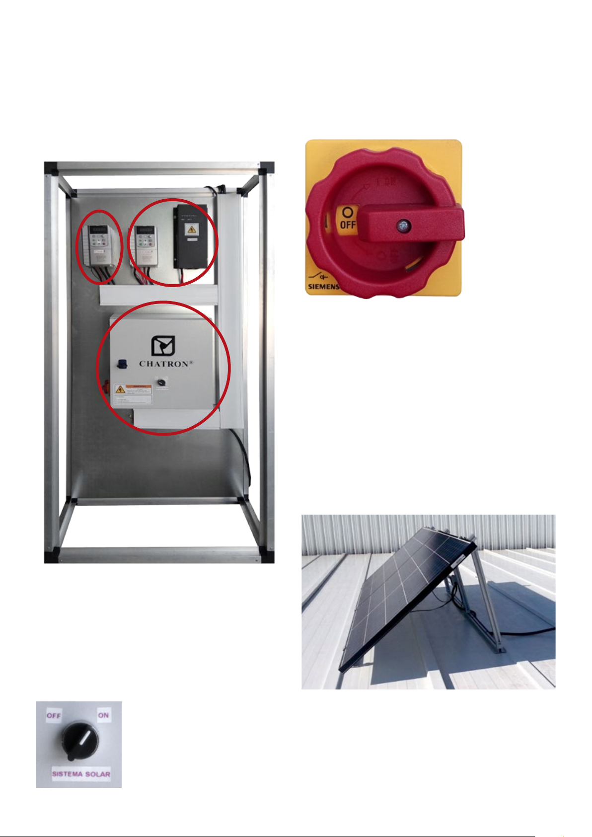
3.2 Monoblock with electrical equipment
The monobloc contains the essential equipment for
the operation of the system. This can be divided into
two subsystems depending on the power source, the
photovoltaic subsystem and the supportive supply
subsystem.
In the photovoltaic subsystem two equipments are pre-
sent; a voltage booster (DC BOOSTER) and a pho-
tovoltaic inverter (INV SOLAR1). It should be noted
that the voltage lift will provide a voltage of 440 VDC
to the inverter. This generates a three-phase voltage of
380V / 50 Hz and will power a second inverter (SO-
LAR INV. 2).
A power cut-off switch (BT) and a protective circuit
breaker (D) are present in the network support subsys-
tem.
Two contactors (K1, K2) are present for switching
between the two supply subsystems. There is an elec-
trical interlock to ensure that only one contactor is
actuated.
+ +
_ _
+ +
_ _
+_+_
+_+_
+_
Sinais
Motor
Placa
Monobloco
Gestão
Energia Rede
(400VAC)
4
A transformer (TRAN) converts the 380 VAC (supplied
by the mains or the first inverter) to 230 VAC, needed
to power the control board, water pump and discharge
valve.
A second inverter (INV SOLAR2) is used to power the
“Biocooler” fan motor. This will receive two signals,
from the control board, to control the speed of rota-
tion.
Figure 2 - monoblock with electrical equipment.
Warning: On the outside of the electrical board door
should contain a warning signal about the existence of
two sources of energy, one of which is photovoltaic.
This signal is important for whoever installs and main-
tains the equipment.
To activate the photovoltaic system there is a se-
lector (S1) that starts the solar inverter.
Figure 3 - control selector of solar photovoltaic system.
• Turning the selector to “ON”, the solar inverter 1 is activa-
ted, powering the Biocooler with photovoltaic energy.
• When turning the selector switch to “OFF”, the
solar inverter 1 is deactivated, if it has power from
the network, the Biocooler will be powered by it.
Placed on the side of the electric panel is a cut-off
panel, which controls the mains supply.
Figure 4 - general network power cut-off panel.
Further information is given in annexes A and B, the
electrical diagrams are presented and a description of
the operation of the solar inverter is made.
It is also recommended to consult the operating ma-
nual of the Biocooler.
4 - Installation
To produce maximum energy, photovoltaic panels
should be properly aligned with the sun and clean (wi-
thout accumulation of litter or dust).
Panel performance improves with colder temperatures.
4.1 Location of photovoltaic panels
The photovoltaic panels should be installed in order
to maximize exposure to the sun. If necessary, the fan
panels can be separated.

5
However, the greater the distance, the greater the sec-
tion of electrical cables.
Caution: if there is shade on the PV panels there will
be a reduction in fan speed or even a stop. Any cell
that is shaded works as a resistor and reduces the
power of the entire PV array.
4.2 Solar Orientation
For better performance, care must be taken to ensure
the orientation of the photovoltaic panels.
In the installation one must look to orient the photo-
voltaic panels in relation to the equator line. (Northern
hemisphere - South direction), (Southern hemisphere
- North direction).
Small adjustments in the EAST or WEST direction do
not significantly affect system performance.
4.3 Inclination of the panels
Attention should also be given to the angle of inclina-
tion of the panels. In each season of the year, there
is a variation in the angle of solar incidence, which
affects the energy production.
In a simple way it can be considered that the inclina-
tion angle of the photovoltaic panels is related to the
latitude of the installation site. An adjustment can also
be made at the incline angle in order to maximize the
yield depending on the season:
• Ideal slope in summer: latitude -15º
• Ideal slope in winter: latitude + 15º
• Ideal year-round slope: latitude -5º
4.4 Distance between rows of panels
When placing the photovoltaic panels in rows; must
take into account the distance between rows to avoid
shading and consequent yield losses.
4.5 Support structure of photovoltaic panels
Caution: A structure designed to withstand wind, easy
to assemble, and most important, safe must be used.
You should follow good practices and defined care for
support structure.
Where roofs do not provide the sun exposure or incli-
nation necessary for the effectiveness of the system,
it may be assumed that it is installed at ground level.
Always consider minimum ground clearance, avoid
shading elements, observe safety conditions.
If you have questions about the structure of support
and display, consult a civil engineer with knowledge of
the site or companies dedicated to the installation of
photovoltaic panels. For better quality and economy,
factory racks are recommended.
5 - System Connections
All connections must be made by qualified personnel
in accordance with local laws, regulations and good
practice.
In order to make the connections, it is recommended
to consult chapter 6 (maintenance) and follow the pro-
cedures indicated therein.
5.1 Connections of the monobloc
+ +
_ _
+ +
_ _
+_+_
+_+_
+_
Signals
Motor
Board
Monoblock
of Energy
Management Network
(400VAC)
Figure 5 - connection diagram of the monoblock.
Make sure that the cables are not in tension when
making connections.
Warning: Make sure you connect the cables of each
element to their terminals. Follow the signs.
Caution: Check the connections in the diagram shown
in this manual. Connecting the cables incorrectly can
damage the system. Use a multimeter to check polarity
and voltage.
5.1.1 Network connection
You must make sure that all phases and ground are
correctly connected. (It is not necessary to connect the
neutral conductor)
Figure 6 - Network cable indication.
5.1.2 Connection of photovoltaic panels
Warning: Photovoltaic panels can generate dangerous
voltages. A 48 V panel can generate close to 100 V
when it is disconnected from the load.
To avoid the risk of electric shock or damage to equip-
ment while working on the installation, cover the photo-
voltaic panels with opaque material (eg card) and leave
a cable off in order to interrupt the electrical circuit.

6
Any damage caused by inattention to these notices
will not be covered by the warranty.
+ +
_ _
+ +
_ _
+_+_
+_+_
+_
MC4
Multibreach
Connector
MC4
Multibreach
Connector
Figure 7 - Connection diagram of photovoltaic panels
The photovoltaic panels used to power the
Biocooler have a nominal power of 250Wp at
270Wp. They are connected in a parallel of two
series (positive terminal with negative) and can
produce about 76 VDC, open.
It is recommended to use MC4 type connectors
and suitable cable for photovoltaic installations
with UV protection, with a minimum cross-section
of 4 mm2. The greater the distance between the
fan and the photovoltaic panels the greater the
section should be, to avoid large voltage drops.
5.1.3. Biocooler links
In order for Biocooler to work in the right direction, you
must make sure to connect:
• The motor power cable to the respective motor terminals,
in the frame of the Biocooler (U, V, W), please check the
direction of rotation, if necessary change a phase;
• The power cable of the control board to the terminals of
the board, in the frame of the Biocooler (F, N, T);
• The motor speed signal cable to the signal terminals on the
Biocooler board (AV, BV, COM), together with the interfa-
ce relays.
Figure 8 - Identification of cables and terminals to be connected in the Biocooler.
5.2 Earth connection, lightning protection
Due to their exposure PV systems are subject to the
effect of direct atmospheric discharges or surges due
to indirect discharges in the vicinity of the installation.
Precautions should be taken to prevent or limit the da-
mage caused by them.
Caution: Local laws, regulations and good practices
for protection against direct and indirect atmospheric
discharges should be followed.
To mitigate the effects of indirect lightning strikes:
• Connect all metallic structural elements of the photovol-
taic panels to each other and the ground bus, in order to
create an equipotential bond between all the elements.
Proper grounding is important, allowing static electricity
to discharge to the earth - preventing lightning.
• It is recommended to use connecting conductors with a
minimum cross-section of 10 mm2 (copper).
• It is recommended that the conductive wires of the pho-
tovoltaic panels be put together in order to avoid inducti-
ve phenomena of indirect discharges.
• It is recommended that the elements of the photovoltaic
panels be separated from the atmospheric discharge
systems.
• It is recommended to use shielded cables in exposed
locations and / or over long cable distances.
If the building does not have a lightning protection
system, the support structure of the photovoltaic
generator must be connected to the ground bus
and incorporated in the equipotential bonding.
If there is a protection system against direct at-
mospheric discharges already implemented in
the building, all metallic structural elements of the
photovoltaic panels must be connected to it and
by the shortest possible path. The goal is to pre-
vent the beam from being able to directly reach
the photovoltaic module. The distance between
the photovoltaic generator and the shaft should
be greater than 2 meters in order to avoid lateral
discharge to the generator.
6 - Maintenance
Caution: All maintenance must be carried out by qua-
lified personnel in accordance with local laws, regula-
tions and good practice.
Each photovoltaic panel produces a voltage greater
than 35V, even without load. Care must be exercised
when handling all elements that are in contact with
their terminals.
On the electric panel will be a DC Booster that will
raise the photovoltaic voltage to about 440 Vdc. There
is danger of serious injury, even death. There is a war-
ning sign on the equipment.

7
Figure 10 - Hazard sign, voltage on photovoltaic panels.
Whenever maintenance work is required, all power
sources (photovoltaic panels, mains, etc.) must be
switched off or disconnected to avoid risk of electric
shock.
Make sure that:
• Turns off the equipment at the control;
• Turn off the disconnecting switches, the photovoltaic pa-
nels, the electricity grid, the equipment present;
• Cover the photovoltaic panels with opaque material (eg
card) and disconnect one of the power cables to ensure
that the circuit is interrupted.
Figure 11 - Warning signal, with installation / maintenance procedure.
7 - Failures
Table 2 - possible Biocoller failures
Faults: Verify: Solution:
Biocooler will
not start
The power switch is set to “ON”
The connections and cables are in
good condition
Check connections,
replace cables
PVs are shaded Remove elements that
cause shadow
Solar inverter has errors Reset the Inverter
Controller is on Check connections
Biocooler
only works
with network
support
PVs are shaded Remove elements that
cause shadow
The connections and cables are in
good condition
Check connections,
replace cables
Solar inverter is faulty Reset the Inverter
The status of the contactor (can
be glued) Contactor Replacement
Biocooler
only works
with PV
The power switch is set to “ON”
Circuit Breaker Check circuit breaker
The status of the contactor (can
be glued) Contactor Replacement
In case of another type of fault that can not be solved,
please contact CHATRON.
In more specific cases you can refer to Appendix B,
where a brief description of the errors of the solar in-
verter is made.
Appendix A - System Wiring Diagram
The system contains the essential equipment for its
operation and will be powered by two sources of ener-
gy. For a better understanding, electrical schematics of
the power and control circuits are presented.
7
Photovoltaiccell
EM12-SP
+10VAI1 AO1 485+ DI1 DI2 DI3 DI4 DI5 HDI
GND AI2 AO2 485- GND COM CME COM +24V COM
TA TB TC
FM DO1 COM
OFF
ON
JP2 J P6
CME
COM
V
I
JP3JP4
1
3
2
1
3
2
1
3
2
1
3
2
JP8
1
3
2
+ (R)
- (T) AC input
Diagram3-2 EM12-SP control circ uit and main circuit wiring
+
+
+
+
Photovoltaic Panels
DC
Booster K1
K2D1
S1
K2
21
22
+
-
+
-
21
22
K2
K1
K1
R1
Inv.
R2
Inv.
D1
(Run Stop
Command)
DI1
(Inverter)
(Always Run)
DI2
(Inverter)
(Low)
DI3
(Inverter)
(High V.)
BT2
COM
COM COM
RC BV RC AV
COM
TA1
TC1
TA2
TB2
Grid
COM (PV System)
Inverter 1
Source
Inverter 2
Source
M
Board
Tran.
1 2
3 4
5 6
1 2
3 4
5 6
DC
DC
Solar
Inv. 1
Solar
Inv. 2 Biocooler
400V AC
400V AC
230V AC
+/R W
V
-/TV U
R
S
T
+/R W
V
-/TV U
Power circuit: A1- power circuit
Table No. A1 - description of the elements present in the power circuit
Des. Equipment Function
BT Disconnector 25 A Network support power button
DBreaker Protection
K2 Contactor I = 9A 3P Uc = 24 V Selection of network support
Tran Transf. S = 100VA Is = 0.43A 400V AC to 230VAC converter
K1 Contactor I = 9A 3P Uc = 24 V Selection of photovoltaic panels
K2 Contactor I = 9A 3P Uc = 24 V Power grid selection
PV + Positive from solar panels Positive terminal of photovoltaic panels
PV - Negative from solar panels Negative terminal of photovoltaic panels
DC booster DC booster Tension lift
Inv.Solar1 Solar Inverter Pot. 2,2KW Photovoltaic inverter for power
Inv.Solar2 Solar Inverter Pot. 2,2KW Photovoltaic inverter for motor
MBiocooler motor 380V Biocooler Fan
Board Biocooler board230V Biocooler Control
Circuito de comando do inversor solar 1 (controlo da
parte fotovoltaica).
A2 - solar inverter control circuit 1
7
Photovoltaiccell
EM12-SP
+10VAI1 AO1 485+ DI1 DI2 DI3 DI4 DI5 HDI
GND AI2 AO2 485- GND COM CME COM +24V COM
TA TB TC
FM DO1 COM
OFF
ON
JP2 JP6
CME
COM
V
I
JP3JP4
1
3
2
1
3
2
1
3
2
1
3
2
JP8
1
3
2
+ (R)
- (T) AC input
Diagram3-2 EM12-SP control circuit and main circuit wiring
+
+
+
+
Photovoltaic Panels DC
Booster K1
K2D1
S1
K2
21
22
+
-
+
-
21
22
K2
K1
K1
R1
Inv.
R2
Inv.
D1
(Run Stop
Command)
DI1
(Inverter)
(Always Run)
DI2
(Inverter)
(Low)
DI3
(Inverter)
(High V.)
BT2
COM
COM COM
RC BV RC AV
COM
TA1
TC1
TA2
TB2
Grid
COM (PV System)
Inverter 1
Source
Inverter 2
Source
M
Board
Tran.
1 2
3 4
5 6
1 2
3 4
5 6
DC
DC
Solar
Inv. 1
Solar
Inv. 2 Biocooler
400V AC
400V AC
230V AC
+/R W
V
-/TV U
R
S
T
+/R W
V
-/TV U

8
Table A2 - description of the elements present in the control circuit of the
solar inverter 1.
Des. Equipment Function
S1 Command selector Active (“RUN”) of solar inverter 1
R1 Relay # 1 (TA1-TC1) of the solar
inverter
Contact “NO” is closed inverter
ready
R2 Relay # 2 (TA2-TB2) of the solar
inverter
Contact “NF” is Open Inverter
Ready
K1 K1 contactor control coil Selection of photovoltaic panels
K2 K2 contactor control coil Power grid selection
Inv. 1 source Solar inverter 24VDC source It feeds the contactor K1
Inv. 2 source Solar inverter 24VDC source Power the contactor K2
COM Common Source Point Contactor supply, signals
DI1 Input signal port # 1 Inverter outdoor activation signal 1
Solar inverter control circuit 2 (Biocooler motor control).
A3 - solar inverter control circuit 2
7
Photovoltaiccell
EM12-SP
+10VAI1 AO1 485+ DI1 DI2 DI3 DI4 DI5 HDI
GND AI2 AO2 485- GND COM CME COM +24V COM
TA TB TC
FM DO1 COM
OFF
ON
JP2 JP6
CME
COM
V
I
JP3JP4
1
3
2
1
3
2
1
3
2
1
3
2
JP8
1
3
2
+ (R)
- (T) AC input
Diagram3-2 EM12-SP control circuit and main circuit wiring
+
+
+
+
Photovoltaic Panels DC
Booster K1
K2D1
S1
K2
21
22
+
-
+
-
21
22
K2
K1
K1
R1
Inv.
R2
Inv.
D1
(Run Stop
Command)
DI1
(Inverter)
(Always Run)
DI2
(Inverter)
(Low)
DI3
(Inverter)
(High V.)
BT2
COM
COM COM
RC BV RC AV
COM
TA1
TC1
TA2
TB2
Grid
COM (PV System)
Inverter 1
Source
Inverter 2
Source
M
Board
Tran.
1 2
3 4
5 6
1 2
3 4
5 6
DC
DC
Solar
Inv. 1
Solar
Inv. 2 Biocooler
400V AC
400V AC
230V AC
+/R W
V
-/TV U
R
S
T
+/R W
V
-/TV U
Table A3 - description of the elements present in the control circuit of the
solar inverter 2.
Des. Equipment Function
RC BV Low speed interface relay Low speed indication to inverter 2
RC AV High-speed interface relay High speed indication to inverter 2
COM Common Source Point Contactor supply, signals
DI1 Input signal port # 1 Inverter outdoor activation signal 2
DI2 Input signal port # 2 Low speed outdoor signal inverter 2
DI3 Input signal port # 3 High speed outdoor signal inverter 2
For more information on solar inverters, please
refer to Annex B.
Annex B - Solar Inverter
The solar inverter converts the DC current of the pho-
tovoltaic panels into AC power in three phases with
about 380 V and a nominal power of 2200W.
Security information:
• Access and handling of the inverter must be carried out by
suitably qualified persons.
• When servicing the inverter ensure that the photovoltaic
panels are plugged in and the power cables disconnected.
• Do not touch the terminals with your hands.
• Do not change the values of the parameters in the solar
inverter, it can cause them to fail and consequently to mal-
function.
7
Photovoltaiccell
EM12-SP
+10VAI1 AO1 485+ DI1 DI2 DI3 DI4 DI5 HDI
GND AI2 AO2 485- GND COM CME COM +24V COM
TA TB TC
FM DO1 COM
OFF
ON
JP2 J P6
CME
COM
V
I
JP3JP4
1
3
2
1
3
2
1
3
2
1
3
2
JP8
1
3
2
+ (R)
- (T) AC input
Diagram3-2 EM12-SP control circuit and main circuit wiring
+
+
+
+
Photovoltaic Panels DC
Booster K1
K2D1
S1
K2
21
22
+
-
+
-
21
22
K2
K1
K1
R1
Inv.
R2
Inv.
D1
(Run Stop
Command)
DI1
(Inverter)
(Always Run)
DI2
(Inverter)
(Low)
DI3
(Inverter)
(High V.)
BT2
COM
COM COM
RC BV RC AV
COM
TA1
TC1
TA2
TB2
Grid
COM (PV System)
Inverter 1
Source
Inverter 2
Source
M
Board
Tran.
1 2
3 4
5 6
1 2
3 4
5 6
DC
DC
Solar
Inv. 1
Solar
Inv. 2 Biocooler
400V AC
400V AC
230V AC
+/R W
V
-/TV U
R
S
T
+/R W
V
-/TV U
B1- basic inverter diagram.
In the power circuit you have:
• terminals + (R) and - (T) for connection of the panels
• photovoltaic;
• terminals U (T1), V (T2), W (T3) for motor connection.
• In the control circuit you have:
• (+ 24V COM), for external sensors and input, up to
200mA,
• digital inputs (DI1 DI6) for inverter control,
• two relays with normally open contacts (TA 1/2 TB 1/2)
and normally closed contacts (TA 1/2 TC 1/2).
The solar inverter display shows the following configu-
ration:
Indicators:
• RUN - inverter status indication (OFF, off, ON);
• LOCAL - inverter control type indication (OFF -
panel, ON - terminal);
• DIR - indication of the direction of rotation of the
motor (OFF - reverse, ON - direct);
• TRIP - torque control (always ON), adjustment in-
dication (blinks slowly), error / fault (blinks quickly).
Button Diagram:
• PGR / ESC - menu entry and exit;
• DATA / ENTER - parameter entry and confirmation of settin-
gs;
• “Up arrow” - increments values, navigates through the
menu;
• “Down arrow” - decrements values, navigates through the
menu;
• “Right arrow” - selects the displayed parameter numbers,
• RUN - start of inverter (on control panel);
9
• STOP / RESET - inverter stop, error / fault clearing;
• MF.K- performs a pre-selected function.
Table No. B1 - list of parameterized functions in solar inverters
description inv. 1 inv. 2 Definition
F0 Basic functions of the
inverter
F0-00 Binary curve selection 1 2 For fan
F0-02 Inverter control 1 1 Terminal Control
F0-03 Inverter control 6 Outside speed control
F0-17 Binary curve selection 20 20 For fan
F0-18 Inverter control 35 20 Terminal Control
F1 Motor parameter assign-
ment functions
F1-01 Rated motor power 1,5 1,2
F1-02 Rated motor voltage 410 380
F1- 03 Rated motor current 21,5
F4
Parameter setting
functions of the inverter
inputs
F4-00 Digital input # 1 1 1 RUN Command Entry
F4-01 Digital input # 2 12 RUN Command Entry
F4-02 Digital input # 3 13 RUN Command Entry
F5
Parameter setting
functions of the inverter
outputs
F5-02 Relay # 1 1 Active when inverter is running
F5-03 Relay # 2 1 Active when inverter is running
F9
Parameter assignment
functions for inverter
faults
FC Inverter control func-
tions
FC-01 Percentage of speed 1 30 Percentage at low speed
FC-02 Percentage of speed 2 75 High Speed Percentage
FE Parameterizing functions
of the solar system
FE-03 Engine type 0 0 Single-phase motor
FE-16 Sleepiness 370 V 250 V Voltage Disabling Inverter
FE-17 Activation voltage 420 V 350 V Voltage that activates inverter
FE-18 Activation time 3600s 0s Time for inverter activation
UO Monitoring
U0-00 Frequency (Hz)
U0-02 Input Voltage
U0-03 Output Voltage
U0-04 Output Current
U0-05 Power of photovoltaic
panels
U0-06 Input current
U0-07 Status of entries
U0-12 Open circuit input
voltage
Ar Alarms
Ar.01 Sleepiness
Ar.02 Low frequency pro-
tection
Ar.04 Overload protection
A4.05 Minimum power pro-
tection
Table No. B2 - list of error codes present in solar inverters.
Table of errors / failures
Code description Solution
Err01
Inverter protection
1. Short-circuit or earthing at the
outlet 1. Eliminate external failures
2. The connecting cable is very 2. Install a filter on the outlet
3. Heating the IGBT 3. Check the air filter and cooling fan
4. Disappearance of terminals 4. Connect the cables properly
5. Control card failure 5. Ask for technical help
6. Power board failure 6. Ask for technical help
7. Failure of IGBTs 7. Ask for technical help
Err02 /
04
Overload during acceleration /
constant speed
1. Short-circuit or earthing at the
outlet 1. Eliminate external failures
2. Motor parameterization is not
performed 2. Perform the parameterization
3. The acceleration time is too short 3. Increase the acceleration time
4. The V / F curve is not the most
appropriate 4. Perform curve adjustment
5. The voltage is too low 5. Set to normal value
6. The start of the operation is carried
out with a rotating motor
6. Select the restart rotation or start the
engine when it stops.
7. A charge was added during
acceleration 7. Remove the added load
8. The power of the inverter is small 8. Select a higher power inverter
Err03
Overload during deceleration
1. Short-circuit or earthing at the
outlet 1. Eliminate external failures
2. Motor parameterization is not
performed 2. Perform the parameterization
3. The deceleration time is too short 3. Increase the deceleration time
4. The voltage is too low 4. Set to normal value
5. A load was added during dece-
leration 5. Remove the added load
6. Braking unit not installed 6. Install the braking unit
Err05 /
06
Overvoltage during acceleration /
deceleration
1. Very high input voltage 1. Set to normal value
2. An external force pulls on the
engine during acceleration
2. Eliminate the external force or install a
braking unit
3. The acceleration / deceleration
time is too short
3. Increase the acceleration / decelera-
tion time
4. Braking unit not installed 4. Install the braking unit
Err07
Constant speed overvoltage
1. Very high input voltage 1. Set to normal value
2. An external force pulls on the
engine during deceleration
2. Eliminate the external force or install a
braking unit
Err08 Power unit failure
The input voltage is not within the
defined range Set the input voltage for the
Err09
Low tension
1. Inverter input failure 1. Clear fault
2. The input voltage is not within the
defined range 2. Set the input voltage for the
3. Out-of-normal DC bus voltage 3. Ask for technical help
4. Rectifying Bridge Failure 4. Ask for technical help
5. Board failure 5. Ask for technical help
6. Main board failure 6. Ask for technical help
10
Err10 Inverter Overload
1. Very high load, locked rotor 1. Reduce load, check engine condition
2. The power of the inverter is small 2. Select a higher power inverter
Err12
Input phase failure
1. Failure of the inputs of the three
phases 1. Eliminate the fault
2. Control board failure 2. Ask for technical help
3. Discharge Protection Board
Failure 3. Ask for technical help
4. Control main board failure 4. Ask for technical help
Err13
Output phase failure
1. Motor cable fault 1. Eliminate the fault
2. The three phases are not balanced 2. Check the motor windings
3. Control board failure 3. Ask for technical help
4. IGBT module failure 4. Ask for technical help
Err14
Overheating in the IGBT module
1. Very high ambient temperature 1. Lower the ambient temperature
2. Air filter blocked 2. Clean the air filter
3. Cooling fan damaged 3. Replace the fan
4. The IGBT module thermistor is
damaged 4. Replace the thermistor
5. The IGBT module is damaged 5. Replace the module
Err18 Current Detection Failure
1. Faulty current sensor 1. Replace sensor
2. Board failure 2. Replace board
Err22
Drive equipment failure
1. Overvoltage
2. Overload
In case of another type of fault that can not be solved,
please contact CHATRON.

11
miiBIOmiiBIO
Instruction
manual for
installation of
Biocooler
Smart Solar

12
miiBIO
miiBIO
Instruction
manual for
installation of
Biocooler
Smart Solar
Table of contents


