Chef's LILIUM User manual

LILIUM
Range Hood User Manual
Compliant to EEE Directive.
Please read this user manual carefully before installing or using your equipment.
Please keep this user manual in a safe place for future use.

Scope of the Range Hood User Manual
Dear customer, the following sections contain information on safe and efficient use of
the equipment. Please read carefully before attempting to install the equipment.
Points to consider before use……………………………………2
Section 1
Technical specifications .......................................................... 3
Section 2
Technical dimensions ............................................................ 4
Section 3
Wiring diagrams .................................................................... 5
Section 4
Mounting instructions ............................................................ 6
Section 5
Operating instructions .........................................................10
Section 6
Maintenance instructions ................................................... 13
Section 7
Fault Descriptions ............................................................ 14
Section 8
1

Points to consider before use
Section 1
1....Electrical connections and installation of the product must be done by qualified service personnel.
In contrary, the product's efficiency may be reduced and serious risks such as noise,
vibration and electricity leakage may occur. In addition, the warranty becomes null.
2....Operating voltage is 200-230 Volt. Do not use under lower or higher voltages.
In contrary, it leads to burnout with the motor windings, failure with the light bulbs and
damages other electrical connection members.
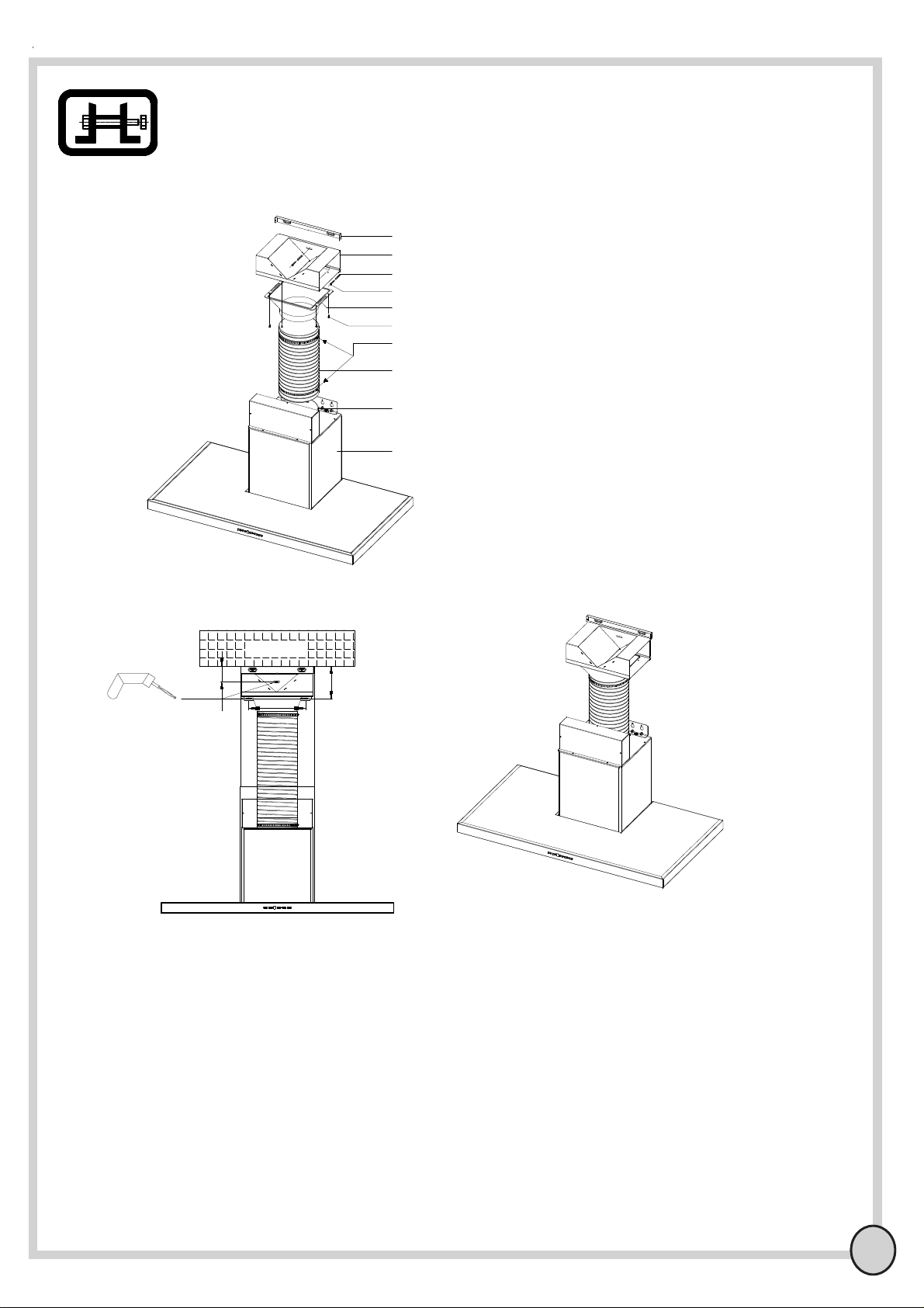
3....The exhaust connection of the product must be made to heating stove, natural gas, heater, ventilation duct.
In contrary, toxic gas leakage occurs or the high air pressure affects other environments.
4....The product must be connected to grounding plug.
In contrary, there is a risk of equipment damage and electrical shock.
5....Flammable food should not be cooked under the range hood.
In contrary, the equipment may take fire, electrical components and metal housing may be damaged.
6....Do not use replace the aluminium filter of the range hood with other materials.
In contrary, other materials may take fire, the suction power may be reduced in addition to the
reduction of service life.
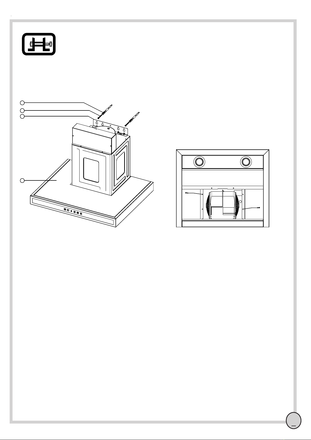
7....Do not connect the range hood to power before completing the installation works.
In contrary, there is a risk of electrical, mechanical problems for the equipment, in addition,
electrical or mechanical accidents may take place.
8....Range hood is designed for use above the stoves in the kitchen of the houses. The product should
not be used out of its intended purpose.
In contrary, the manufacturer shall not assume any responsibility in connection with possible
problems and accidents. In addition, the warranty of the equipment becomes null.
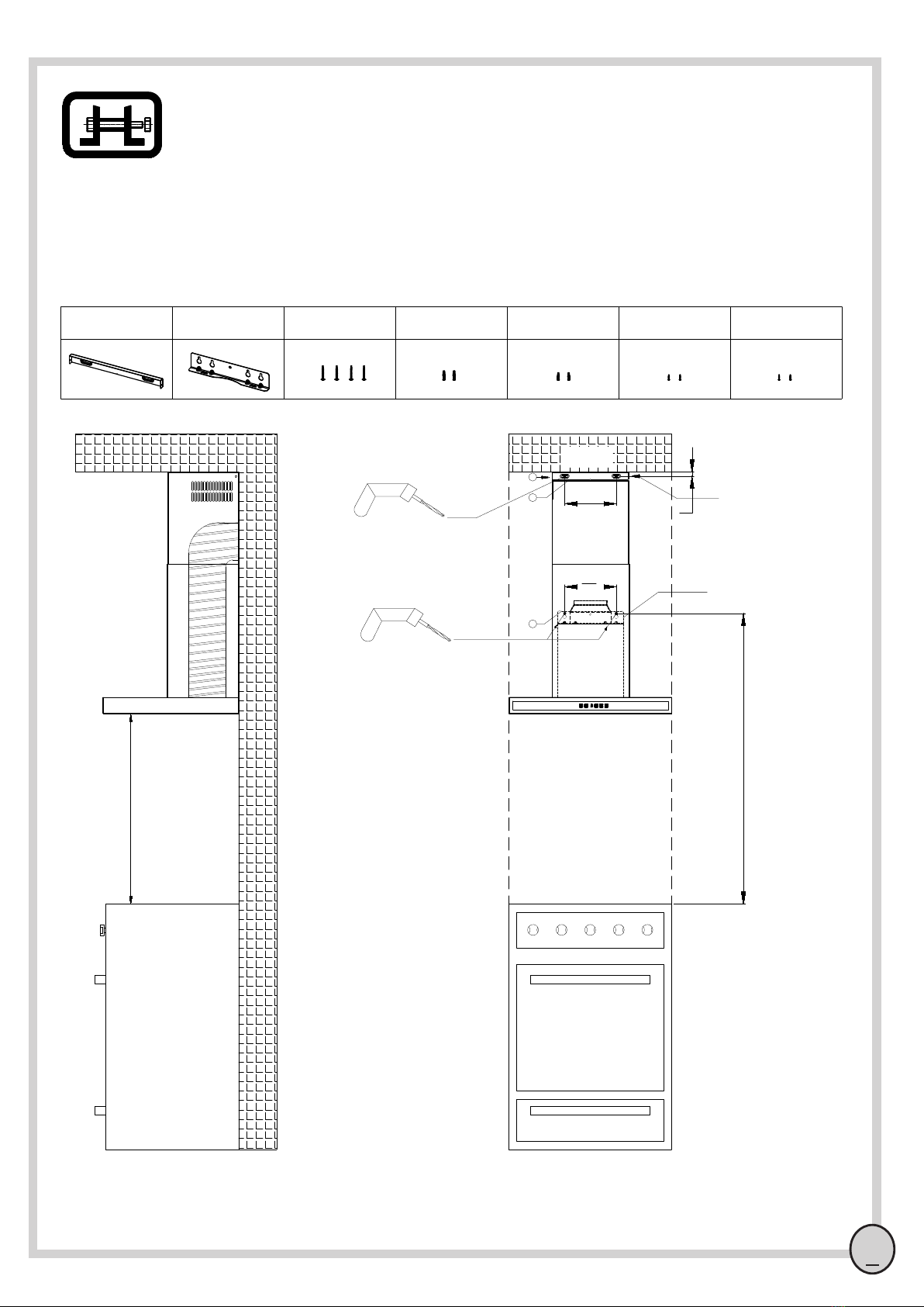
9....Make sure that the wall where the range hood will be mounted is capable of bearing its load.
In contrary, negative consequences may occur.
10....Keep children away from the equipment and do not allow them to use it.
In contrary, negative consequences may occur.
11.... Do not touch the halogen lamp as it heats on the surface.
In contrary, various accidents may take place.
12....Ventilation in the room must be at sufficient levels when the electrical range hood is used at the same time with the
equipment fuelled with gas or other fuels. (air-filtering equipment may be excluded)
In contrary, various accidents may take place.
13....Electrical range hood must be cleaned periodically, surfaces of the product must be clean.
In contrary, oil accumulates on the range hood surface and it may cause range hood to take fire.
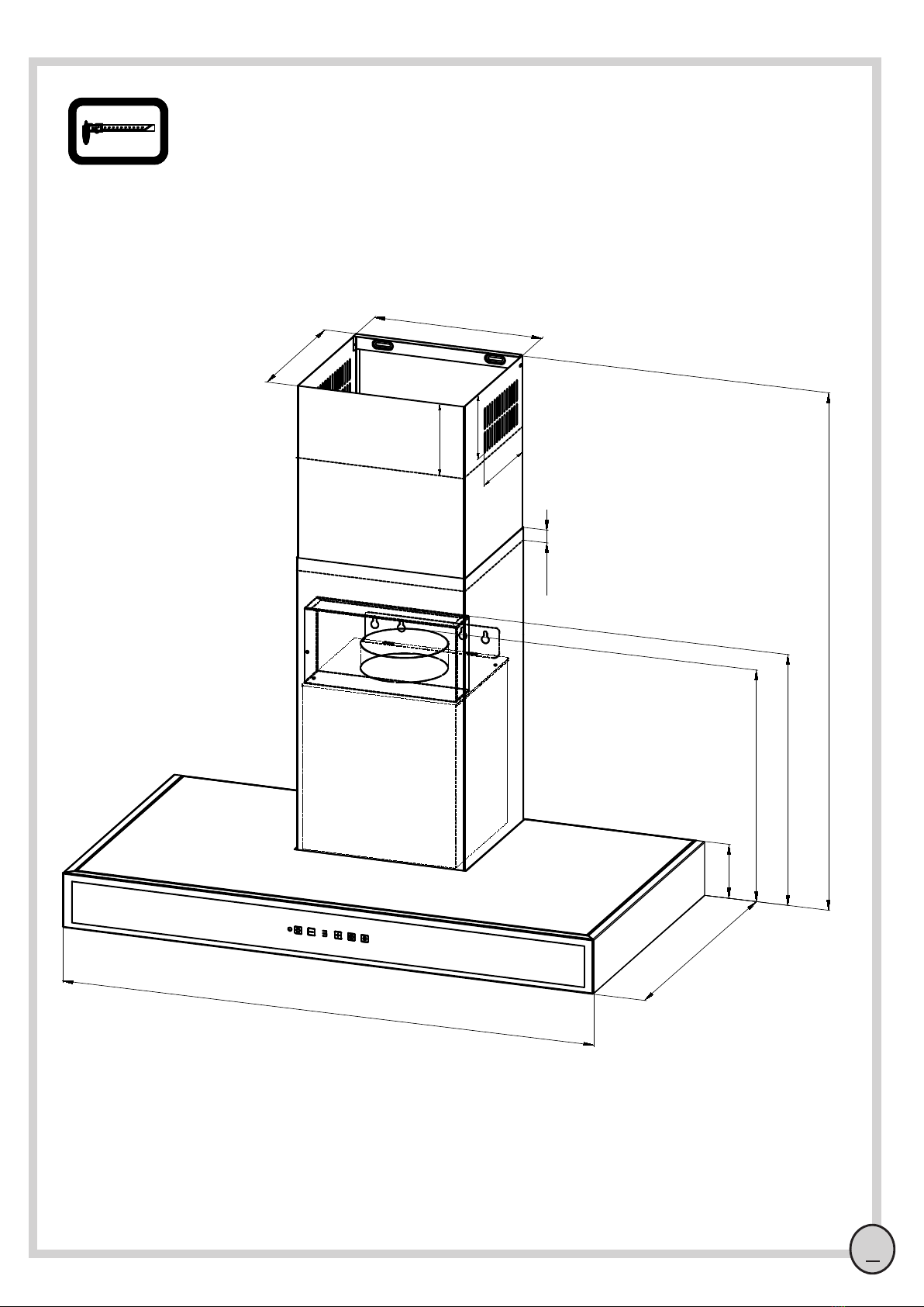
14....The product must be mounted on the wall in accordance with the dimensions specified in the mounting diagrams.
In contrary, the range hood may take fire, toxic gasses are not extracted and performance loss occurs.
2

3
Technical specifications
Section 2
Range hood technical specifications
Length 598/898
Control Panel Soft Touch Control
Width 500
Suction Power 550 M³
Height Min. 530 - Max. 1010
Light Power 2x20W
Motor Power 115W
Supply Voltage 220-230V 50Hz
Total Power 155W
1
2
3
4
5
Figure A1
1- Flue Top
2- 220V Cable
3- Lower Flue Panel
4- Panel
5- Control buttons
Air Outlet Pipe Diameter 120 mm/150 mm

4
Technical dimensions
Section 3
Figure A2
285
265
Min 530 - Max 1010
20
598-898
500
40
400
470
172
120
108

5
Wiring diagrams
Section 4
Figure A3
Soft touch control wiring diagram
Data cable entry
Lamp
(Max 200W)
380W
Max
220-230V 50Hz Power
input
Data cable entry
Button card
Transformer
4. Speed
N
3. Speed
2. Speed
1. Speed

6
Figure A4
1 2
Flue connection apparatus 4x50 rysb screw Ø8 mm threaded insert Ø7 mm threaded insert 3,9x9,5 rysb screw
Mounting plate 4x35 rysb screw
34 5 67
Range hood mounting distances
Mounting instructions
Section 5A
1065
190
190
Oven & Stove
1
2
7
14
Min. 65 cm
CEILING
drill with Ø8 drill bit.
drill with Ø7 drill bit.
Flue connection apparatus
Mounting plate

7
Mounting instructions
Mounting steps;
1- Drill the required holes in accordance with the distances specified in Figure A4.
2- Drive 2 x Ø8 mm threaded inserts (1) and 2 x Ø7 threaded inserts into the wall.
3-Drive 4x50 rysb screws into the threaded insert making sure that the spacing between the wall
and the screw head is 2-4 mm.
4- Lift the product, slide the screw head into the large hole on the motor connection plate & wall
mounting plate and slightly push the product against the wall and downwards, make sure that screw
heads are properly inserted into the hole.
5- Open the product cover and remove 4x50 rysb(1) screws as shown in Figure A5.
6 - Check the steps you applied and continue with the flue assembly.
Figure A5
Section 5B
Range mounting
1- Ø8 mm threaded insert
2- 4x50 rysb screw
3- Motor connection plate & wall mounting plate
4- Panel
1
2
3
4
Figure A6
Bottom view

8
Figure A7
Mounting instructions
Range hood flue assembly and completion of the mounting works
1
2
4
5
6
7
3
Section 5C
Note : You are required to buy Ø120 mm or Ø150 mm semi-rigid aluminium duct and 2 connecting clamps
for the flue assembly. We recommend you to use Ø150 mm semi-rigid duct.
1- Flue mounting apparatus
2- Ø7 Threaded insert
3- 3,9x9,5 pan head screw
4- 4x35 rysb screws
5- Flue Top
6- Lower Flue Panel
7- Motor connection & wall mounting plate
Flue assembly;
1-Insert lower flue panel into the flue top.
2- Screw the lower flue panel to the range by using 3,9x9,5 screw(8) as shown in the figure.
3- Drive Ø7mm threaded inserts into the holes drilled in accordance with the dimensions provided in Figure A4.
4- Screw the flue mounting apparatus to the wall by using 4x35 rysb(4) screws.
5- Lift the flue top and fasten to the flue mounting apparatus on sides by using 3,9x9,5 pan head screws(3) as
shown in Figure A7 and complete the mounting works.
Figure A8
2
3
4
1

9 919
9
Air directing apparatus installation process:
1- Install the hood body and chimney installation apapratus according to the instruction in the Figure A5.
2- Drill the holes of the air directing apparatus pursuant to the instructions in figure A10 and mount it by
using Ø7 dowel (3) and 3,9 x 35 rysb screw (4).
3- Mount the air directing connection plastic onto the air directing body sheet by using 4 units 3,9 x 9,5
rysb screws (6).
4-Fix the aluminium elliptic pipe (8) to the motor air outlet (9) and mount it by using the clamp (7). 5-
Raise the aluminium elliptic pipe (8) upwards and mount it to the air directing connection plastic (5) by
using a clamp (7).
6-Complete the installation process according to the instructions in Figure A8.
Section 5D
2
5
8
9
7
185
60
125
CEILING
Figure A10
1
10
drill with Ø7 drill bit.
3
6
4
Figure A9
Figure A11
Mounting instructions
1- Chimney installation apparatus
2- Air directing body sheet
3- Ø7 mm dowel
4- 3,9*35 screw
5- Air directing connection plastic
6- 3,9x9,5 rysb sheet screw
7- Ø150 mm clamp
8- Ø150 mm elliptic pipe
9- Motor air outlet
10- Hood body

10
Operating instructions
Section 6
Soft Touch control usage information
Plus butonu: Increases the engine rpm up to the 4th rpm. When the button is kept pressing, rpm
increases successively. When the button is presses and then left, the engine increases one by one.
Display: Displays the rpm of the engine position, aluminium filter and carbon filter fill warning, timer
function running and the lamp is switched on or off positions.
Timer button: When timer button is pressed while the engine is running, the number of that rpm starts
flashing on the screen. Upon 15 flashings the lamp switches off in the engine is running. When timer n
is pressed again, flashing stops and timer is cancelled.
Lamp button: Switches on or off the lamp. When the lamp is switched off, point segment is displayed
in the screen.
Aluminium filter warning: Upon 30 hours engine running time, “f” is displayed on the screen as
aluminium filter fill warning. After the filter is cleaned and (-) button is kept pressed for 5 seconds
“e” is displayed on the screen and aluminium filter time is reset.
Carbon filter warning: Upon 300 hours engine running time, “c” is displayed on the screen as carbon
filter fill warning. After the filter is cleaned and (+) button is kept pressed for 5 seconds “e” is displayed
on the screen and aluminium filter time is reset.
Air filtering function: If the timer button is pressed for 2 seconds when the fan is turning, the air
filtering function is activated. The fan turns at low speed for 10 minutes and stops for 50 minutes
when the air filtering function is on. This cycle is repeated for 24 hours. The fan effect is not
displayed, instead, "0" is displayed when this function is activated.
Air filtering function is cancelled by pressing the time button for 2 seconds (the fan continues
normal operation at speed 1) or by pressing on-off button to stop the motor.
M.On/Of button: Switches on or off the engine. The engine starts at the 2nd rpm at the start.
Minus button: Reduces the engine rpm up to the 1st rpm. When the button is kept pressing,
rpmreduces successively. When the button is presses and then left, the engine reduces one by one.

11
Figure A12
Carbon filter replacement;
Carbon filter is an optional component produced with the purpose of using the range hood without
flue connection. If you want to use the product without flue connection, a carbon filter must be
purchased from the authorized technical services.
Removing the carbon filter;
1- Unplug the product and turn off the relevant fuse switch.
2- Remove the aluminium filter in order to reach to the carbon filter.
3- Pull the carbon filter nail frontward and pull it downwards.
Fitting the carbon filter;
Fit the nails of the carbon filter to the rear side and fixt it by pushing upwards.
Maintenance instructions
Unplug the product or turn off the switch before commencing maintenance works on the product.
Aluminium filter cleaning:
Aluminium filter is used to trap the oil particles in the air, therefore it is blocked based on the
frequency of use and leads to performance loss with the product. Accumulated grease layer poses a
risk of catching fire. Therefore, we recommend you to clean your filter once in two weeks. For
cleaning, remove the filters as shown in Figure A12, wash with liquid detergent, rinse with water and
reinsert after drying. Do not use acidic, corrosive cleaning agents for cleaning the filters. Do not start
the product without reinserting the filter. The colour of the filters may change as they are cleaned.
This is normal and does not indicate the requirement of filter replacement. We do not recommend you
to clean your aluminium filter in dishwasher. If the aluminium filter cannot be cleaned, you can buy a
new one from the authorized technical service.
Aluminium filter removal;
Press the aluminium filter lock and remove by pulling down.
Aluminium filter placement;
Place the rear tabs of the aluminium filter in the filter
holders in the rear side of the range, and then press
the filter lock and push the filter up and place the
filter in parallel position to the ground level in order to
inset into the filter channel and release the lock.
Section 7A

12
Maintenance instructions
Section 7B
Installation of the motor box and electrical connections
Halogen lamp replacement:
Lamp holder
G4 Halogen lamp
Lamp glass holder
Lamp glass
Figure A13
- Unplug the product and turn off the relevant fuse switch.
- Remove the middle glass holder by using a thin blade screwdriver as shown in the figure.
- Turn the halogen lamp in the arrow direction, pull and remove the lamp and replace with the
new one.
- Inset the middle holder by pressing the tabs.
- Connect to the electricity and check whether it functions properly.

13
Maintenance instructions
Section 7C
Cleaning;
- Use a wet cloth with liquid detergent in order to clean the external surface of the range hood.
Do not use corrosive and abrasive cleaning agents.
Caution;
- You may cause fire if you do not follow the rules on filter cleaning and replacement.
Warning;
- Suction performance will be reduced by 30% to 40% when carbon filter is used.
- Carbon filter should not be washed. It should be replaced once in 4 months under normal
conditions.
- There is a risk of fire if the oil filters are not cleaned regularly and if the carbon filter is not
replaced at the end of its service life (approximately 4 months).

14
Fault Descriptions
Section 8
Please read the following information carefully before calling an authorized technical service.
Range hood does not function!
- Make sure that the power cable of the equipment is connected to the power socket.
- Check the fuse switches.
Range hood functions but the light is off!
- Unplug the product and check whether the lamps are intact and they are loose.
- There may be a situation stopping the functioning of the light on/off button, please check.
The product performance is low!
- If the product has flue connection, check the connection and make sure the flue outlet is not
blocked.
- Check whether the aluminium filter and carbon filter are clean.
The range hood vibrates!
- Make sure that the mounting screws of the equipment are not loose.
-Check whether there are any objects between the range hood and the wall.
The equipment displays 'F'!
- It is the warning for cleaning the aluminium filter, please read the instructions of use carefully for solving
the problem.
The equipment displays 'C'!
- It is the warning for cleaning the carbon filter, please read the instructions of use carefully for solving the
problem.

Table of contents
Other Chef's Ventilation Hood manuals
Popular Ventilation Hood manuals by other brands

Omega
Omega ORC97G instruction manual

Maestro
Maestro MEZZO MMZ430BS Installation guide and use and care manual

Zephyr
Zephyr AK9358BS Use, care and installation guide

Nederman
Nederman Pneumatic Track System instruction manual

Baumatic
Baumatic BES900BGL instruction manual

KORTING
KORTING KHA 4970 X Cylinder User instructions