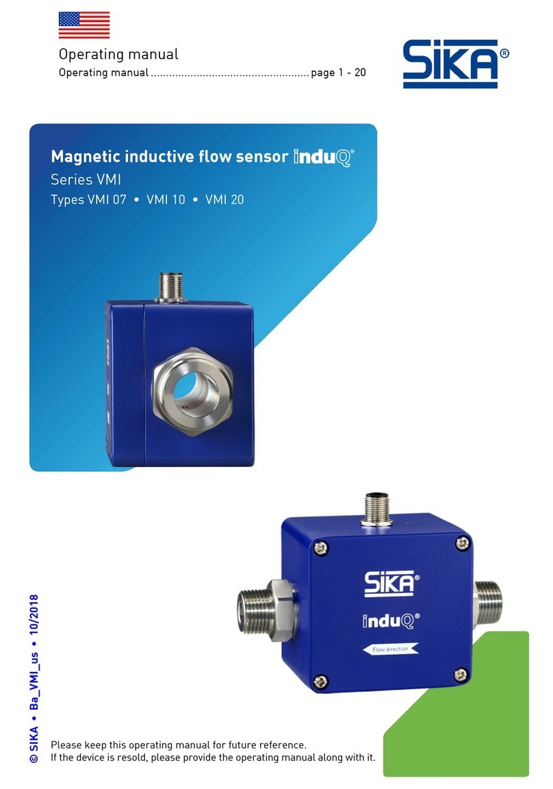
ChemInstruments DDM-206A-S User manual

CHEMINS INSTRUMENT CO., LTD Rev2020-04 1 / 11
www.chemins-tech.com
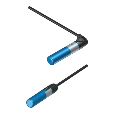
DDM-206A-S Online Salinity Sensor
User Manual
YANTAI CHEMINS INSTRUMENT CO., LTD.
Tel:0535-3463801 0571-89870583
E-mail:service@chemins-tech.com service@chemins-env.com
Website:www.chemins-tech.com
Address: No. 15, Entrepreneurship Base, Development Zone, Zhaoyuan City,
Shandong Province

CHEMINS INSTRUMENT CO., LTD Rev2020-04 2/11
www.chemins-tech.com
User Notes
Please read this manual carefully before use and save it for reference.
Please follow the operating procedures and precautions in this manual.
When receiving the instrument, please carefully open the package and check
whether the instrument and accessories are damaged due to shipping. If any
damage is found, please inform the manufacturer and distributor immediately,
and keep the package for return.
When the instrument fails, do not repair it yourself. Please contact the
maintenance department of the manufacturer directly.

CHEMINS INSTRUMENT CO., LTD Rev2020-04 3/11
www.chemins-tech.com
Content
User Notes.......................................................................................................2
Ⅰ、 Application environment................................................................................4
Ⅱ、 Technical performance and specifications.....................................................4
1. Technical parameters.................................................................................... 4
2. Dimensional drawing....................................................................................5
Ⅲ、 Installation and electrical connection............................................................5
1. Installation...................................................................................................5
2. Electrical connection................................................................................... 5
Ⅳ、 Maintenance and maintenance..................................................................... 6
1. Use and maintenance...................................................................................6
2. Calibration..................................................................................................... 6
Ⅴ、 Quality and service.........................................................................................6
1. Quality assurance........................................................................................ 6
2. Accessories and spare parts........................................................................7
3. After-sales service commitment.................................................................7
Appendix data communication.................................................................................. 8

CHEMINS INSTRUMENT CO., LTD Rev2020-04 4/11
www.chemins-tech.com
Ⅰ、Application environment
Sea water / heavy salt water / various water supply / industrial water treatment.
Signal output: RS-485 (Modbus/RTU protocol).
Convenient connection to third-party equipment such as PLC, DCS, industrial control computer,
general controller, paperless recording instrument or touch screen.
Immersion installation with 3/4 NPT pipe thread for easy submersible installation or installation
in pipes and tanks.
IP68 protection grade.
Ⅱ、Technical performance and specifications
1. Technical parameters
Model
DDM-206A-S
Measuring range
0~70.0PSU
Resolution
0.1PSU
Precision
±1.5%F.S.,±0.5℃
Working temperature
0~65℃
Working pressure
<0.6MPa
Power supply
12~24VDC
Signal output
RS-485(Modbus/RTU)
Wetted material
ABS(Default)/ POM
Mounting method
Immersion mounting, 3/4 NPT thread
Cable length
5 meters, other lengths can be customized
Temperature compensation
Auto temperature compensation(Pt1000)
Calibration
Two-point calibration
Power consumption
0.2W@12V
Protection grade
IP68

CHEMINS INSTRUMENT CO., LTD Rev2020-04 5/11
www.chemins-tech.com
2. Dimensional drawing
Ⅲ、Installation and electrical connection
1. Installation
Note: At least 2 cm from the bottom and side walls of the container during installing and testing.
2. Electrical connection
a) Red line - power cord (12 ~ 24V)
b) Black line - ground (GND)
c) Blue line - 485A
d) white line - 485B
After wiring is completed, it should be carefully checked to avoid incorrect connections before

CHEMINS INSTRUMENT CO., LTD Rev2020-04 6/11
www.chemins-tech.com
powering up.
Cable specification: Considering that the cable is immersed in water (including sea water) for a long
time or exposed to the air, the cable has certain corrosion resistance. The outer diameter of the
cable is Φ6 mm and all interfaces are waterproof.
Ⅳ、Maintenance And Maintenance
1. Use and maintenance
Conventional electrodes require periodic cleaning and calibration, and the maintenance cycle is
determined by the customer based on his or her own operating conditions. Cleaning method for
conventional electrode: Remove the attached material with a soft brush (be careful to avoid
scratching the surface of the electrode), then rinse with distilled water, and then perform
calibration.
Electrode cleaning method:
The inductive salinity electrode is basically maintenance-free, and its normal operation will not
be affected by pollution or slight scaling of the shell.
If it needs clean, use a soft brush or sandpaper to remove attachments, and then clean with
distilled water, calibration after operation.
Because the inductive electrode often works in the environment which is easy to scale or dirty,
the cleaning strength can be increased appropriately. Slight scratches on the electrode surface
will not affect the normal operation of the electrode, but it is necessary to avoid penetrating
the electrode shell.
2. Calibration
a) Zero calibration
Rinse the sensor with distilled water and blot the liquid with filter paper. Place the sensor on the
power supply and place it in the air for about 3 minutes. After the value is stable, perform zero
calibration.
b) Slope calibration
Place the electrode vertically in a standard solution (20% full scale - full scale). Note that the
electrode is at least 2 cm from the bottom and side walls of the vessel for slope calibration. The
calibration instructions are detailed in the appendix.
Ⅴ、Quality and service
1. Quality assurance
The quality inspection department has standardized inspection procedures, advanced and
perfect testing equipment and means, and strictly in accordance with the regulations, to do

CHEMINS INSTRUMENT CO., LTD Rev2020-04 7/11
www.chemins-tech.com
72-hour aging test and stability test on the product, and not to allow one unqualified product to
leave the factory.
The receiving party directly returns the product batch with a failure rate of 2%, and all the costs
incurred are borne by the supplier. The reference standard refers to the product description
provided by the supplier.
Guarantee the quantity of goods and the speed of shipment.
2. Accessories and spare parts
This product includes:
1 sensor
1 copy of the instruction manual
1 certificate
Calibration solution (optional)
3. After-sales service commitment
The company provides local after-sales service within one year from the date of sale, but does not
include damage caused by improper use. If repair or adjustment is required, please return it, but
the shipping cost must be conceited. Damaged on the way, the company will repair the damage of
the instrument for free.

CHEMINS INSTRUMENT CO., LTD Rev2020-04 8/11
www.chemins-tech.com
Appendix Data Communication
1. Data format
The default data format for Modbus communication is: 9600, n, 8, 1 (baud rate 9600bps, 1 start bit,
8 data bits, no parity, 1 stop bit).
Parameters such as baud rate can be customized.
2. Information frame format
a) Read data instruction frame
06 03 xx xx xx xx xx xx
Address Function code Register address Number of registers CRC check code (low byte first)
b) Read data response frame
06 03 xx xx......xx xx xx
Address Function code Bytes Answer data CRC check code (low byte first)
c) Write data instruction frame
06 06 xx xx xx xx xx xx
Address Function code Register address Write data CRC check code(low byte first)
d) Write data response frame (same data command frame)
06 06 xx xx xx xx xx xx
Address Function code Register address Write data CRC check code (low byte first)
3. Register address
Register
address
Name
Instruction
Number of
registers
Access
method
40001
Measured value
4 double-byte integers, which
4(8 bytes)
Read

CHEMINS INSTRUMENT CO., LTD Rev2020-04 9/11
www.chemins-tech.com
(0x0000)
+ temperature
are the measured value, the
measured number of decimal
places, the temperature
value, and the decimal value
of the temperature value.
44097
(0x1000)
Zero calibration
Calibrate in the air, the read
data is 0.
1(2 bytes)
Write
44101
(0x1004)
Slope
calibration
Calibrated in a known
standard solution (20% full
scale - full scale), the read
value is actual value of
standard solution *10
1(2 bytes)
Write
44103
(0x1006)
Zero calibration
value
The data is read out as a zero
offset.
1(2 bytes)
Read
44105
(0x1008)
Slope calibration
value
The read data is the slope
value x 1000.
1(2 bytes)
Read
44113
(0x1010)
Temperature
value
Calibrated in solution, the
written data is the actual
temperature value x 10; the
read data is the temperature
calibration offset x 10 .
1(2 bytes)
Write/Rea
d
48195
(0x2002)
Device address
The default is 6, writing data
range 1-127.
1(2 bytes)
Write/Rea
d
48225
(0x2020)
factory reset
The calibration value is
restored to the default value
and the write data is 0. Note:
The sensor needs to be
calibrated again after
resetting.
1(2 bytes)
Write
4. Command example
a) Start measurement instructions
Function: Obtain the conductivity value and temperature of the measuring probe; the unit of
temperature is Celsius, and the value of conductivity is mS/cm (or uS/cm);

CHEMINS INSTRUMENT CO., LTD Rev2020-04 10 /11
www.chemins-tech.com
Request frame:06 03 00 00 00 04 45 BE
Response frame: 06 03 08 01 02 00 01 00 B0 00 01 90 48
Example of reading:
For example: Salinity value 01 02 means hexadecimal reading salinity value, 00 01 means
the salinity value has no decimal point , which is converted to the decimal value of 25.8.
The temperature value 00 B0 represents the hexadecimal reading temperature value, and
00 01 indicates that the temperature value has a decimal point and is converted to a decimal
value of 17.6.
b) Calibration instructions
Zero calibration
Function: Set the sensor's conductivity zero calibration value; here the zero calibration is
performed in the air;
Request frame: 06 06 10 00 00 00 8C BD
Response frame: 06 06 10 00 00 00 8C BD
Slope calibration
Function: Set the sensor's conductivity slope calibration value; here the slope value is based on
the actual standard solution value, and the calibration is taken as an example with 5000μS/cm;
Request frame: 06 06 10 04 01 F4 CD 6B
Response frame: 06 06 10 04 01 F4 CD 6B
c) Set the device ID address:
Function: set the Modbus device address of the sensor;
Change the device address 06 to 01. The example is as follows:
Request frame:06 06 20 02 00 01 E3 BD
Response frame: 06 06 20 02 00 01 E3 BD
5. Error response
If the sensor does not correctly execute the host command, it will return the following format
information:
Definition
Address
Function code
Code
CRC check
Data
ADDR
COM+80H
xx
CRC 16
Number of bytes
1
1
1
2
a) CODE: 01 –Function code error
03 – Data is wrong
Conductivity value
Temperature value
01 02 00 01
00 B0 00 01
Table of contents

