MPE CHAIN-VEY User manual

GENERAL INFORMATION pg. 2-3
Safety Recommendations and Warnings
Safety Instructions
Equipment Identification
180° DRIVE UNIT pg. 4-5
180° TURNAROUND UNIT pg. 6
DISCHARGE UNIT pg. 7
CONVEYOR PIPING pg. 8-10
INLETS pg. 10
CHAIN / DISCS pg. 11-12
FLOOR / CEILING SUPPORTS pg. 12
OPERATION pg. 13-16
Setting the Tension
Testing
Operation
Flow Control
MAINTENANCE pg. 17-20
Troubleshooting
Equipment Lubrication
Parts Replacement
ELECTRICAL pg. 21-25
Drive Unit
Shock Relay
Tension Switch
Solenoid Valves

2
General Information:
Safety Recommendations and Warnings
MPE Chain-Vey conveyors are built and tested to comply with current safety regulations and laws.
To continue this practice of safety, MPE requires that the following is noted:
Before installing, operating, or servicing the conveyor, it is necessary to completely understand the
information found in this manual.
The tubular drag conveyor is designed to be operated only as specifically stated in this manual.
MPE can only warrant safety and proper performance of equipment that is used in accordance with
this manual.
All planning, installation, transport, assembly, commissioning, maintenance and repair (mechanical
and/or electrical) may only be completed by qualified personnel.
Safety Instructions
1. Do not attempt to install, connect power to, operate or service Chain-Vey equipment
without proper instructions, or until you have been thoroughly trained in its use.
2. Do not attempt to work on, clean, or service the conveyor until the power has been turned
off and locked out. If and when it is necessary to momentarily start and stop (jog) the
conveyor, use extreme caution and ensure that all personnel are clear of the conveyor
chain.
3. Do not manually override or electrically bypass any protective device.
4. Do not connect power to, or operate the conveyor unless all moving parts are covered and
all covers, guards, safety grids and maintenance panels are in place and securely fastened.
5. Do not place any part of your body or loose clothing within the feed hoppers, discharge
hoppers, or any other access point on the conveyor while it is in operation.
6. All conveyor inlet and discharge openings and access panels must be completely enclosed
to prevent human access when the conveyor is running and remain enclosed until power
has been turned off and locked out.
7. All protective covers, guards, grates, maintenance panels and warning decals must be kept
in place. Any equipment with damaged, defective, or missing protective devices must be
taken out of service until such protective devices can be repaired or replaced.
No portion of this document may be reproduced in any format without written authorization by MPE
3
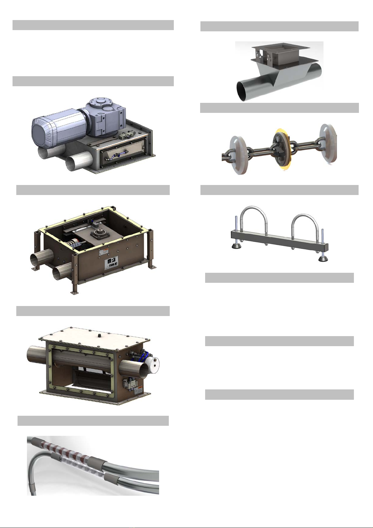
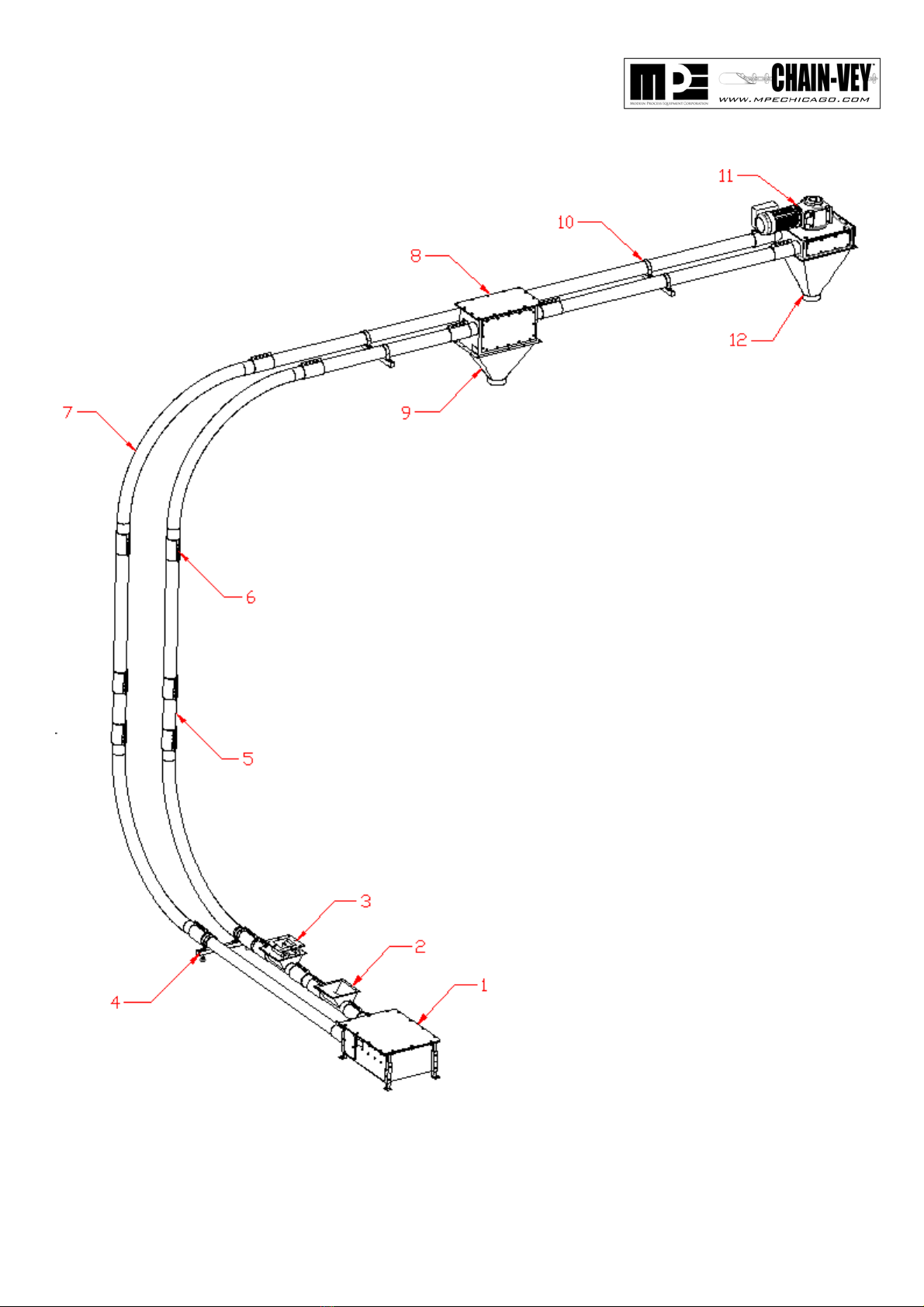
Equipment Identification
1. 180° Tensioning Turnaround Unit
2. Product Inlet
3. Product Inlet with optional Flow Baffle
4. Double-pipe Floor Support
5. Product Sight Glass
6. Compression Coupling
7. Sweep Elbow
8. Rotary Discharge
9. Rotary Discharge – Discharge Transition
10. Double-Pipe Suspension Support
11. 180° Drive Unit
12. Drive Unit – Discharge Transition
Note: Equipment layout is shown only as an example. The component numerical designations are
shown for reference purposes only.

4
180° Drive Unit:
Used in conjunction with the 180° turnaround unit, the 180° drive unit is the mechanism that pulls
the chain through the system. The chain is pulled through the drive unit by a sprocket which is
powered by an electric gearmotor. The drive unit may be run in either direction, and the chain can
enter or exit through either of the two ports. The drive unit is installed at the end of the circuit
system. Typically, the drive unit is used as the final or single discharge point.
The drive unit is to be ceiling suspended or base mounted. The unit may be oriented horizontally
or vertically. For ceiling suspension, (4) 1/2”-13 thru holes are located at the top of the drive unit.
These mounting holes may be used for running through threaded rod or placing eye-bolts.
*the unit weighs app. 430 lbs (195.0 kg)
Note: The Drive unit is shipped with a breather plug already mounted on the
gearmotor.Once the unit is installed, the black rubber seal located on
the breather MUST BE REMOVED. In addition, the oil level should
be checked. (see Equipment Lubrication pg. 16)
Table of contents


