Chemtrac Auto Clean UV254 User manual


Chemtrac UV Auto Clean - v 2.1
Chemtrac, Inc. 1
Chemtrac, Inc.
1555 Oakbrook Dr. Suite 100
Norcross, GA 30093
(770) 449-6233

Chemtrac UV Auto Clean - v 2.1
Chemtrac, Inc. 2
1 Contents
2Overview_____________________________________________________________________________3
3Safety _______________________________________________________________________________4
3.1 Safety Instructions _________________________________________________________________4
4Technical Specifications_________________________________________________________________5
5Installation____________________________________________________________________________5
5.1 Unpacking and Inspection ___________________________________________________________5
5.2 Assembly ________________________________________________________________________6
5.3 Mounting_________________________________________________________________________6
5.4 Plumbing_________________________________________________________________________7
5.4.1 Connecting a UV254 Analyzer ____________________________________________________8
5.5 Electrical and Communication ________________________________________________________9
6Start Up and Operation_________________________________________________________________10
6.1 Start Up_________________________________________________________________________10
6.2 Operation _______________________________________________________________________11
7Cleaning ____________________________________________________________________________12
8Cleaning Configuration_________________________________________________________________13
8.1 UVM5000 Organics Monitor Menu ____________________________________________________14
9Maintenance _________________________________________________________________________15
10 Parts and Accessories _________________________________________________________________15
11 Cabinet Dimensions and Clearance_______________________________________________________16
12 Warranty ____________________________________________________________________________17
List of Tables
Table 1: Automatic Cleaning Module Specifications _______________________________________________5
Table 2: Items and quantity list for unpacking ____________________________________________________5
Table 3: Commercial cleaning solutions________________________________________________________12
Table 4: Menu functions and configuration for Auto Clean System ___________________________________13
Table 5: UVM5000 menu selection of cleaning configuration _______________________________________14
Table 6: Maintenance tasks and frequency for Auto Clean system___________________________________15
Table 7: Spare parts for Auto Clean system_____________________________________________________15
Chemtrac UV Auto Clean - v 2.1
Chemtrac, Inc. 3
2 Overview
Thank you for purchasing from Chemtrac, Inc.
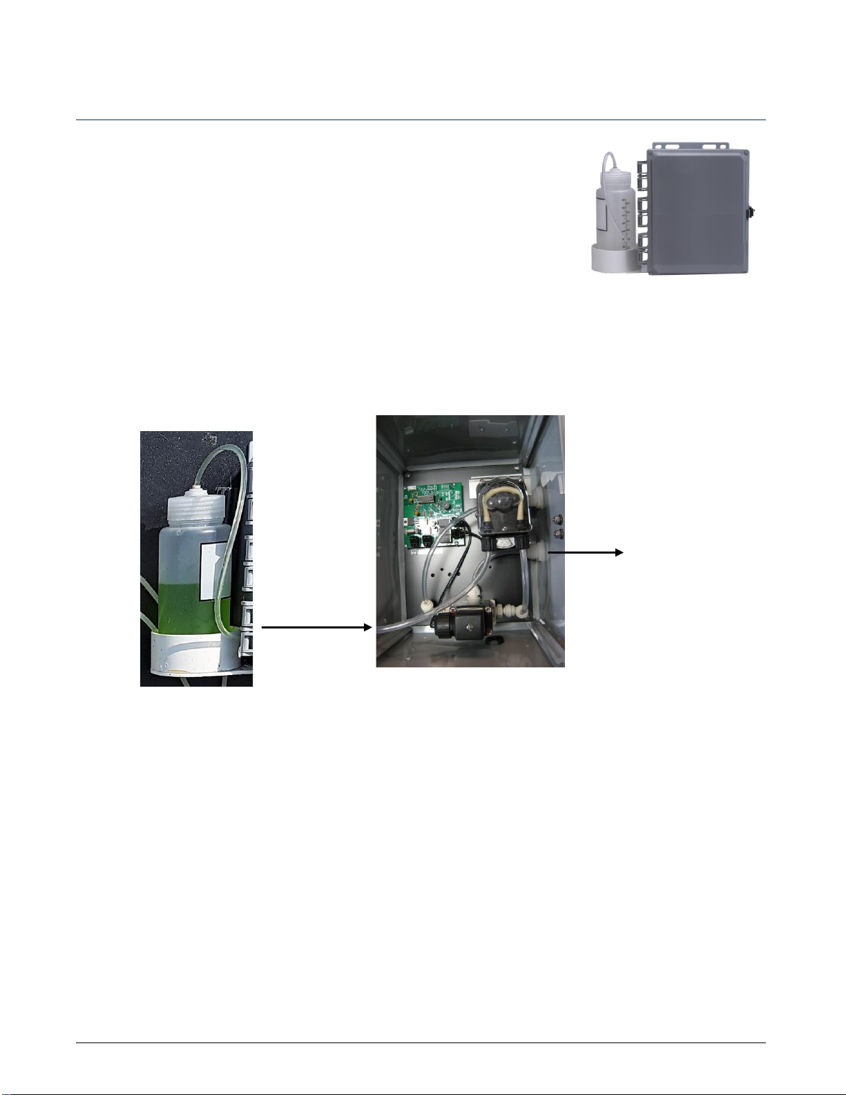
The Automatic Cleaning Module is a chemical cleaning system for use with the
Chemtrac UVM5000 UV254 Organics Monitor, and the UV1 UV254 Organics
Sensor. The purpose of the system is to reduce and clean any deposition/fouling
in the analyzer flow cell.
The Auto Clean and the UV254 analyzer are plumbed so that process water flows through the cleaning module
to the analyzer. When a cleaning cycle starts, the Auto Clean temporarily stops the flow of process water, and
instead pumps cleaning solution from its cleaning fluid bottle to the analyzer flow cell. This can be done on an
automated periodic schedule, or on an immediate basis through manual intervention.
A portion of cleaning fluid is recaptured and directed back into the bottle after a cleaning cycle is completed.
Analyzer measurement resumes after the tubing is rinsed of residual cleaning fluid by the reestablished flow of
process water.
The cleaning system is controlled through the Operator Interface of the Chemtrac UV254 analyzer. From here,
the system is enabled, and a cleaning frequency is selected.
Cleaning of the flow cell is best achieved when cleaning frequency and cleaning fluid work in unison to prevent
the accumulation of fouling agents inside the flow cell.
On schedule,
cleaning fluid drawn
from bottle by
pump.
Cleaning fluid to
flow cell for a
10-minute hold
time.

Chemtrac UV Auto Clean - v 2.1
Chemtrac, Inc. 4
3 Safety
3.1 Safety Instructions
Please read and follow all safety instructions outlined in this owner’s manual prior to
installation and/ or operation.
1. Visually inspect the device prior to operation. If it seems broken or damaged in any way, do not use.
Contact Chemtrac, Inc. for a replacement.
2. Ensure that all responsible personnel carefully read this manual before installing or servicing the device.
3. Failure to properly install and maintain this device may impact its effectiveness and warranty.
4. Improper use of this device may cause injury.
Chemtrac UV Auto Clean - v 2.1
Chemtrac, Inc. 5
4 Technical Specifications
Table 1: Automatic Cleaning Module Specifications
CHARACTERISTIC
TECHNICAL DATA
CLEANING FREQUENCY
User configurable cleaning cycle
CLEANING CAPACITY
1L cleaning fluid bottle
DIMENSIONS
10”high x 18” wide x 6” deep (25 cm x 46 cm x 15 cm)
ENCLOSURE
Wall mountable
FLUID CONNECTIONS
¼” (6 mm) push-to-connect fittings and flex tubing
ELECTRICAL
Operates from 24 VDC
STORAGE TEMP.
-20°C to +60°C (-4°F to +140°F)
OPERATING TEMP.
0°C to 45°C (32°F to 113°F)
WEIGHT
10 lb (4.5 kg)
WETTED MATERIAL
Polypropylene, Marprene
WARRANTY
1-year limited warranty
5 Installation
5.1 Unpacking and Inspection
To begin, remove the Auto Clean system from the packaging and
carefully inspect the product to ensure that no visible damage has
occurred during shipping. The following items will be packed inside
the box:
Table 2: Items and quantity list for unpacking
ITEM
Automatic Cleaning Module
1L Cleaning Fluid Bottle
Bottle Holder
Power and Communication Cable
Owner’s Manual
Please ensure all items are unpacked and accounted for before moving on to assembly.
Chemtrac UV Auto Clean - v 2.1
Chemtrac, Inc. 6
5.2 Assembly
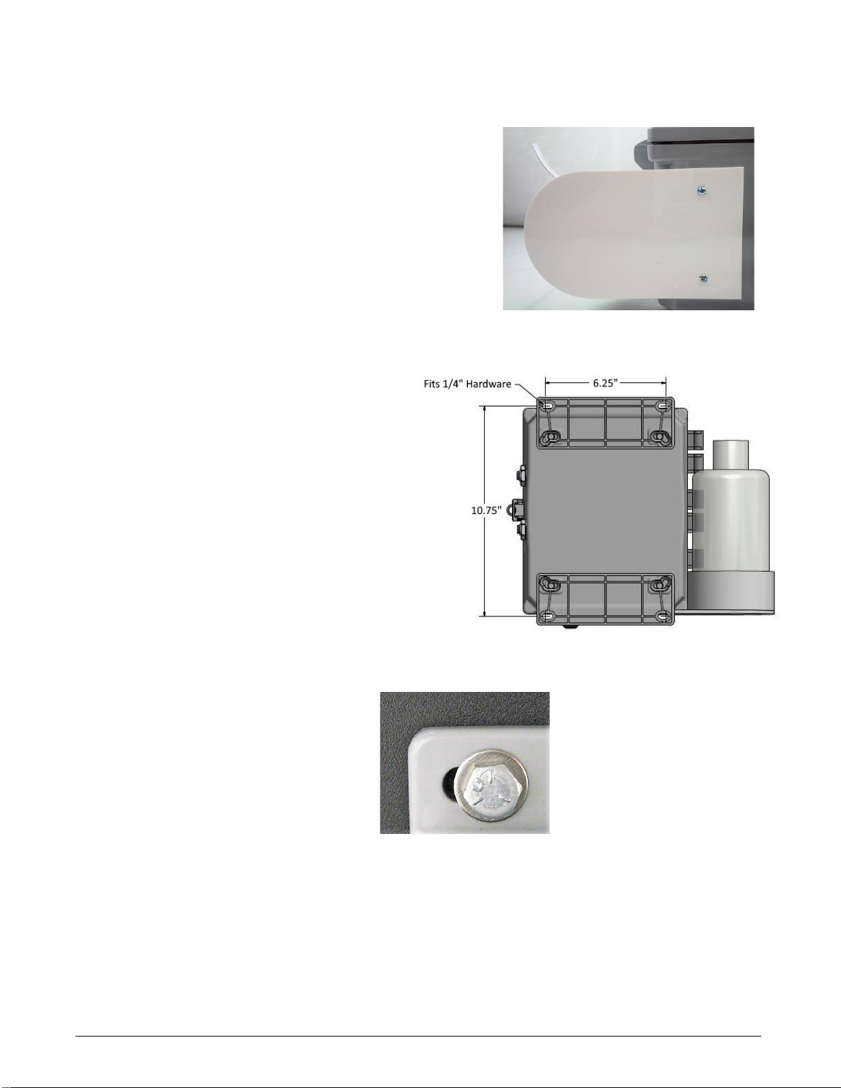
BThe cleaning fluid bottle holder must be mounted onto the Auto
Clean system from the underside of the enclosure as shown in
Figure 5.1. Fittings are supplied with the holder.
After mounting the enclosure, fill the 1L bottle with cleaning fluid.
Recommended fluids are outlined in Section 7 –Cleaning. Connect
the tubing from the system to the spout on the bottle.
5.3 Mounting
The system is enclosed in a wall-mountable cabinet.
The cabinet should be attached at all four of the
mounting holes provided (top left and right; bottom left
and right in Figure 5.2).
Use screws and washers that are sturdy enough to
support the cabinet weight of approximately 10 lbs.
Cabinet dimensions are to the nearest 1/8 inch. Refer
to Section 11, Cabinet Dimensions and Clearance for
drawings of dimensions and clearance.
The expanded view at right (Figure 5.3) shows
an example of a ¼” bolt and washer inserted in
the front side of the cabinet.
The system should be mounted in a convenient
location near the UV254 analyzer to be cleaned
(less than 2 ft.).
Figure 5.1: Cleaning fluid bottle
holder
Figure 5.2: Mounting cabinet
Figure 5.3: Sample bolt and washer
for attachment

Chemtrac UV Auto Clean - v 2.1
Chemtrac, Inc. 7
5.4 Plumbing
Process water from a pressurized source flows through the Auto Clean system and into the connected
instrument for measurement.
Piping is required to be ¼” OD flex tubing of whatever pressure rating is needed for the particular site. Figure
5.4 displays the two push-to-connect inlet and outlet ports on the side of the Auto Clean system.
The Auto Clean system is connected in series with the instrument to be cleaned. It is preferred to keep the
tubing between the Auto Clean and instrument less than 2 feet. Configurations for the UV254 analyzer are
outlined in Figure 5.6.
Note: If installing with a Dual Feed system, the Auto Clean will be installed prior to the Dual feed on the Stream
1 port (See Figure 5.5). Refer also to the Dual Feed manual for further instructions.
Figure 5.4: Auto Clean system ports
From Process
To Analyzer
To Stream 1
From Process
To Analyzer
Figure 5.5: Auto Clean plumbing with Dual Feed

Chemtrac UV Auto Clean - v 2.1
Chemtrac, Inc. 8
5.4.1 Connecting a UV254 Analyzer
1. Connect ¼” OD flex tubing from a pressurized source to
the IN port on the Auto Clean system.
2. Connect ¼” tubing from the OUT port on the Auto Clean
to the IN port on the side of the analyzer.
3. Connect ¼” tubing to the OUT port on the analyzer and
divert to drain.
IMPORTANT: The test water must be allowed to flow unrestricted to
drain so that no significant pressure will occur inside the flow cell.
IMPORTANT: If system was supplied with Dual Feed Option, be sure
to review the Dual Feed manual for additional plumbing information.
Figure 5.6: UV254 Analyzer and Auto Clean plumbing connections
Water In
Water Out
(To Drain)
Auto Clean System

Chemtrac UV Auto Clean - v 2.1
Chemtrac, Inc. 9
5.5 Electrical and Communication
The power and communication line from the UV254
analyzer feeds into the Auto Clean system via an
electrical conduit fitting at the bottom of the cabinet. The
system is powered and controlled through the
connected UV254 analyzer.
Connections at the analyzer are shown in Figure 5.7.
•White and green wires to terminal 7 and 8 (Clean
Out). Polarity is not important.
•Black wire to terminal 9 (24 VDC Out -).
•Red wire to terminal 10 (24 VCD Out +).
The terminal block connections at the Auto Clean
system control board are shown in Figure 5.8.
1. Connect the white and green wires leading from
the UV254 analyzer to the right terminal block.
Polarity is not important.
2. Connect the power wires leading from the
analyzer to the left terminal block. The black
power wire connected to the left (-) terminal and
red wire to the right (+) terminal.
Figure 5.8: Auto Clean system communication and power
connections
Figure 5.7: UV254 Analyzer connections
Chemtrac UV Auto Clean - v 2.1
Chemtrac, Inc. 10
6 Start Up and Operation
6.1 Start Up
Once plumbing and electrical connections have been made, you need to enable the cleaning system and enter
settings for cleaning configuration. This is accomplished through the UVM5000 Operator Interface. Section 8
gives more detail on menu selections.
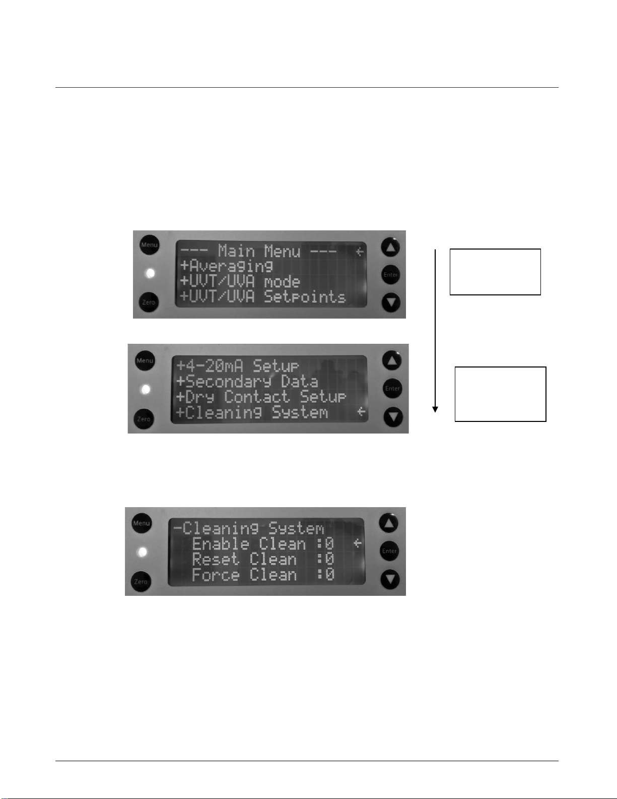
From the main menu, press the down arrow button to scroll to the +Cleaning system menu. Access the Main
Menu page by pressing the Menu button. You may need to press the button more than once to have the screen
displayed.
1. To enable the cleaning system, scroll down to ‘Enable Clean’ and press Enter to enable the cleaning
system. The 0 turns to 1, which signifies the item has been selected and therefore, enabled.
Scroll down by
pressing the down
arrow repeatedly.
Press Enter to
expand the
+Cleaning System
menu.

Chemtrac UV Auto Clean - v 2.1
Chemtrac, Inc. 11
2. Scroll down from the last entry until the +Clean Frequency menu is displayed. Expand the menu by
pressing the Enter button. Seven selections are available. The default is 4: 3 days. De-select a
frequency by scrolling to it, and then pressing Enter to remove the checkmark. Conversely, select an
option by scrolling the arrow to it, and then press Enter to place a checkmark beside it.
Implementing these two settings is the minimum you need for set up. The system is ready for use. For all other
functions, refer to Section 8, Cleaning Configuration. If the system encounters any problems, associated alarms
or warnings are displayed on the Operator Interface of the UVM5000.
To turn the Auto Clean system off, disable the device by removing the checkbox opposite Enable Clean
(reverse of step 1).
6.2 Operation
The system consists of a 3-way stainless solenoid valve, a peristaltic pump, and a 1L chemical cleaner storage
container. The cleaning process is initiated automatically on a preselected time interval or can be manually
triggered.
The cleaning process consists of the following steps:
1. Solenoid shuts off the process water flow to the analyzer flow cell (LED turns on).
2. Solenoid opens flow from peristaltic pump to the analyzer flow cell.
3. Peristaltic pump turns on and pumps cleaning solution into the analyzer flow cell.
4. The pump turns off and the system waits to allow the chemical cleaning solution to remove fouling and
staining present on the walls of the quartz flow cell.
5. The pump turns on in the opposite direction to re-capture the cleaning chemical.
6. Solenoid valve opens the water flow from the process to purge out the cleaning solution (LED turns off).
The process is now complete.
During the cleaning cycle, the measured UVA/UVT value shown on the M series instrument is held to the last
value measured before the cycle started and released after the purge time is complete.
Chemtrac UV Auto Clean - v 2.1
Chemtrac, Inc. 12
7 Cleaning
The Auto Clean system comes with a 1L chemical storage bottle. After
a cleaning cycle, approximately 85% of the used cleaning fluid is
pumped back into the bottle reducing the need to replenish the fluid
on a regular basis.
Two important factors that affect the sensor performance are the
cleaning fluid used to clean the flow cell, and how often the flow cell
is cleaned (cleaning frequency).
Cleaning Frequency
The optimum frequency of cleaning is quite variable depending on
the amount and type of fouling agents in the water. This will be
dependent on the application and installation point.
For wastewater, a higher frequency will be required (ex. 1-24hrs)
whereas high purity water will require a lower frequency (ex. once a
month). Each installation will be different and require configuration
onsite.
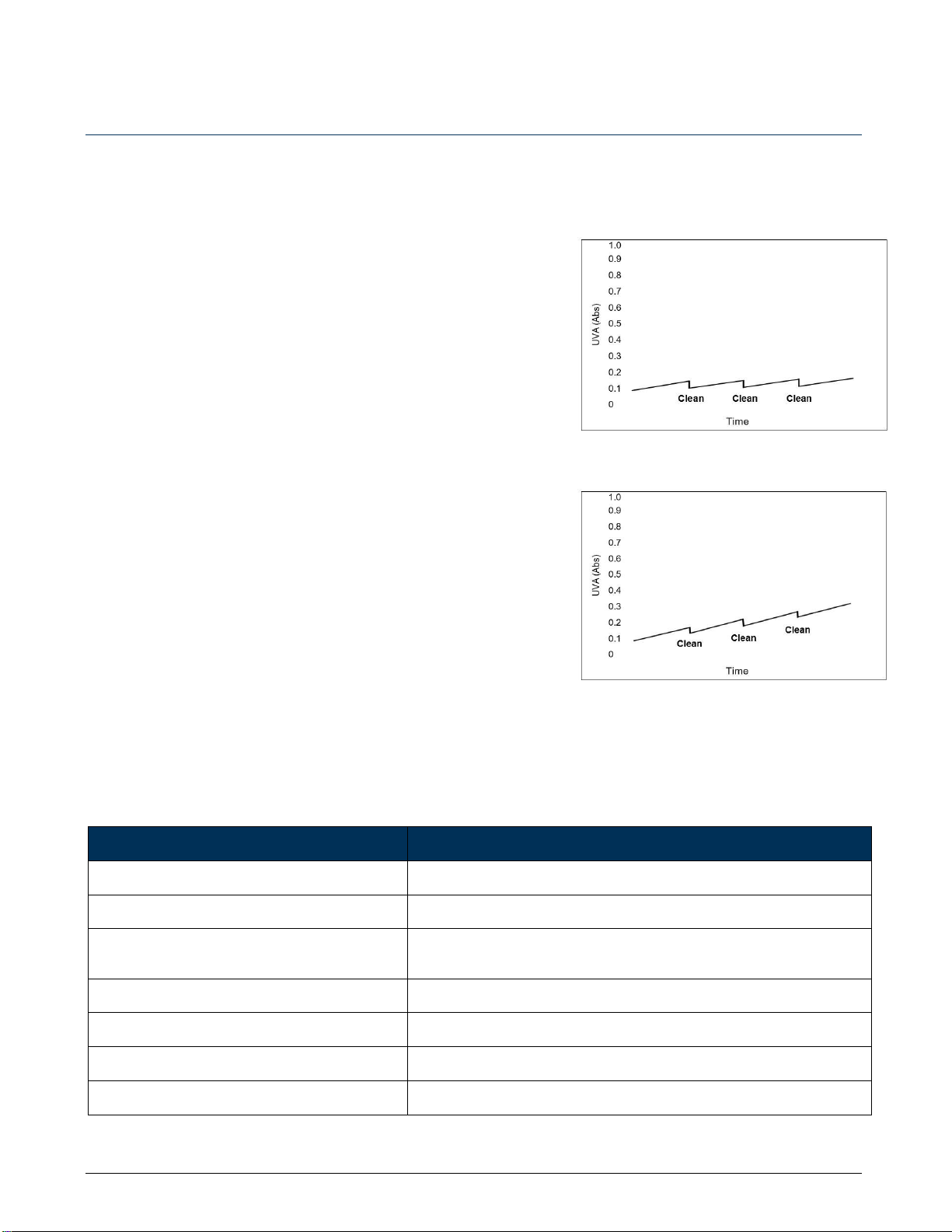
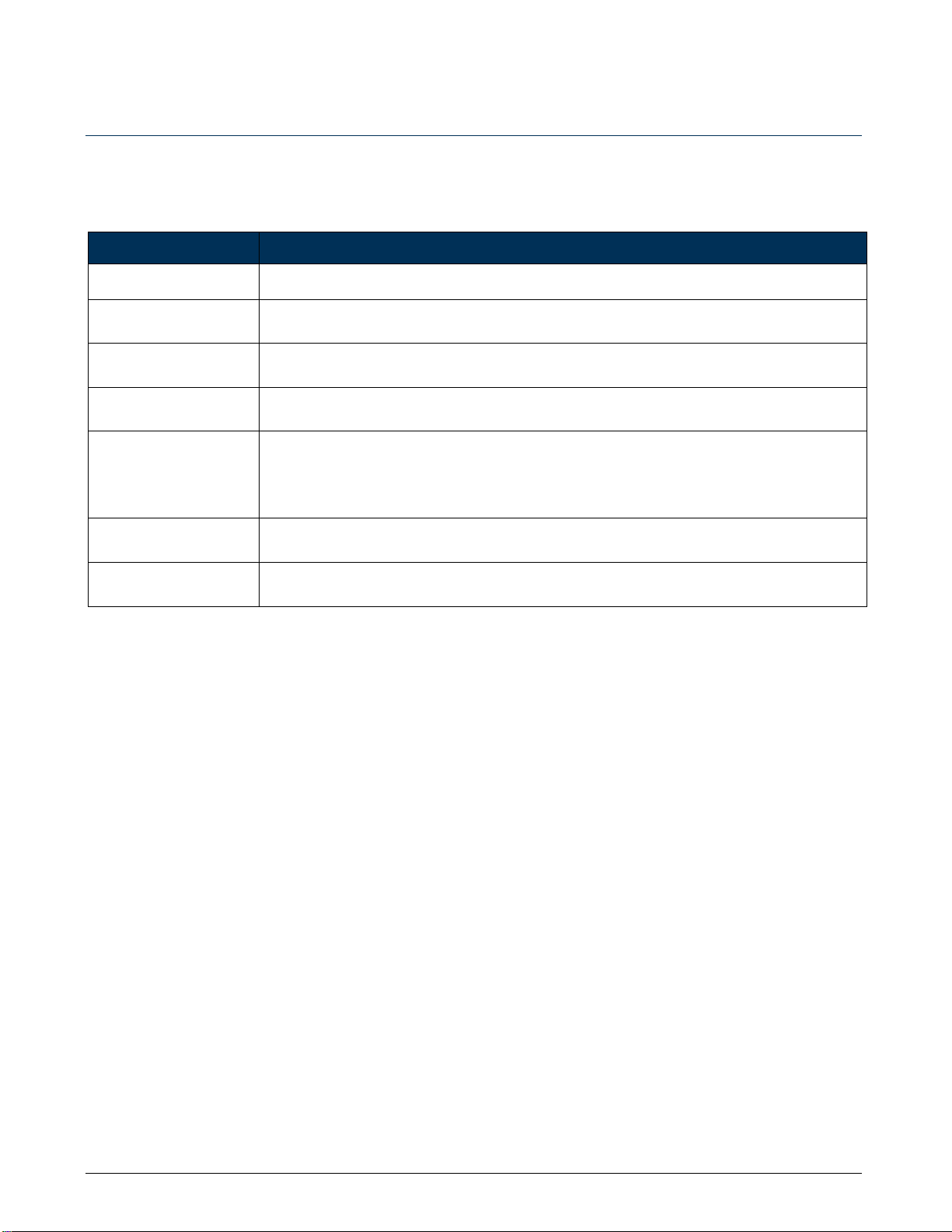
Once in operation, observe the flow cell for signs of fouling prior to
the first cleaning cycle. If fouling is present, increase the cleaning
frequency accordingly. The measured data can also be observed for
signs of a saw tooth effect as shown in Figure 7.1. If the saw tooth
shows an upward trend, as shown in Figure 7.2, the sensor is drifting
and cleaning frequency must be increased.
Cleaning Fluid
Selecting an effective cleaning solution is essential for optimal
performance. The following commercial cleaning solutions and acids
are readily available to remove common fouling agents.
Table 3: Commercial cleaning solutions
SOLUTION
FOULING AGENTS
Lactic Acid <20% solution (CLR®)
Removes lime, calcium, rust, magnesium, and other dissolved minerals
Sulfamic Acid <10% solution (Lime Away®)
Removes lime, calcium, rust, magnesium, and other dissolved minerals
Phosphoric Acid <30% solution (Rust Off,
Hagasen Blue)
Removes lime, calcium, rust and color staining
Citric Acid <20% solution
Removes mineral scaling
Sodium Hypochlorite <6% solution (Not bleach)
Removes oil, grease and biofilm
Acetic Acid <20% solution
Removes oil and grease
Sulfuric Acid <10% solution
Removes oil and grease
Figure 7.1: Effective cleaning
Figure 7.2: Inadequate cleaning
Chemtrac UV Auto Clean - v 2.1
Chemtrac, Inc. 13
8 Cleaning Configuration
The Auto Clean system is controlled and configured through the M series analyzer. Below is a general
summary of the functions and configurations for the system.
Table 4: Menu functions and configuration for Auto Clean System
MENU
DESCRIPTION
-Cleaning System
Enable Clean
Cleaning must be enabled for the Auto Clean system to operate.
Reset Clean
When the cleaning fluid is changed or refilled, the user must do a Reset to reset the counter on
the cleaning bottle.
Force Clean
At any time, the user can trigger a cleaning cycle by selecting force clean. This does not
interfere with the normal cleaning schedule.
Pumping Time
Pumping Time allows for configuration of time (in seconds) the cleaning system pumps
cleaning fluid to the sensor. The pumping time should be configured to ensure the cleaning
fluid reaches and fills the quartz flow cell prior to the 10-minute holding period. Longer
distances between the cleaning system and sensor will require a longer pumping time. Default
setting is 120 seconds, suitable for a tube length of 24-36 inches.
-Clean Frequency
Clean Frequency allows the frequency of cleaning to be configured i.e. hour, day, week, or
month. Default is 3 days.
-Alarms
If enabled, alarm conditions are displayed on the main menu.

Chemtrac UV Auto Clean - v 2.1
Chemtrac, Inc. 14
8.1 UVM5000 Organics Monitor Menu
Table 5: UVM5000 menu selection of cleaning configuration
MENU ITEM
DESCRIPTION
CLEANING SYSTEM
Enable Clean
Press Enter then up/down to select 0 or 1 to turn on automatic cleaning system
Reset Clean
Press Enter then up/down to select 0 or 1 to reset fluid alarms after refilling fluid
Force Clean
Press Enter then up/down to select 0 or 1 to force a cleaning cycle
Pumping Time
Press Enter then up/down to select 60, 90 or 120 seconds
CLEAN FREQUENCY
0: No Cleaning
1: 4 hours
2: 12 hours
3: 24 hours
4: 3 days
5: 1 week
6: 2 weeks
7: 1 month
Select
Press Enter then up/down to select cleaning frequency (value 0-7)
ALARMS
Cleaning
Alarm status (0= no alarm 1=alarm)
Clean Fluid Empty
Alarm status (0= no alarm 1=alarm)
Clean Fluid Low
Alarm status (0= no alarm 1=alarm)
Chemtrac UV Auto Clean - v 2.1
Chemtrac, Inc. 15
9 Maintenance
Following the manufacturer’s recommended maintenance schedule will ensure optimal performance of the
product. Parts and accessories are outlined in Section 10.
A standard recommended maintenance schedule for the Auto Clean system is as follows:
Table 6: Maintenance tasks and frequency for Auto Clean system
FREQUENCY
TASK
Site Specific
•Automatic cleaning cycle configuration to ensure proper sensor cleaning
Weekly
•Visual inspection for leaks, corrosion or other issues.
•Inspect cleaning fluid levels. Replenish if necessary.
•View connected analyzer or controller display for configured cleaning alarms.
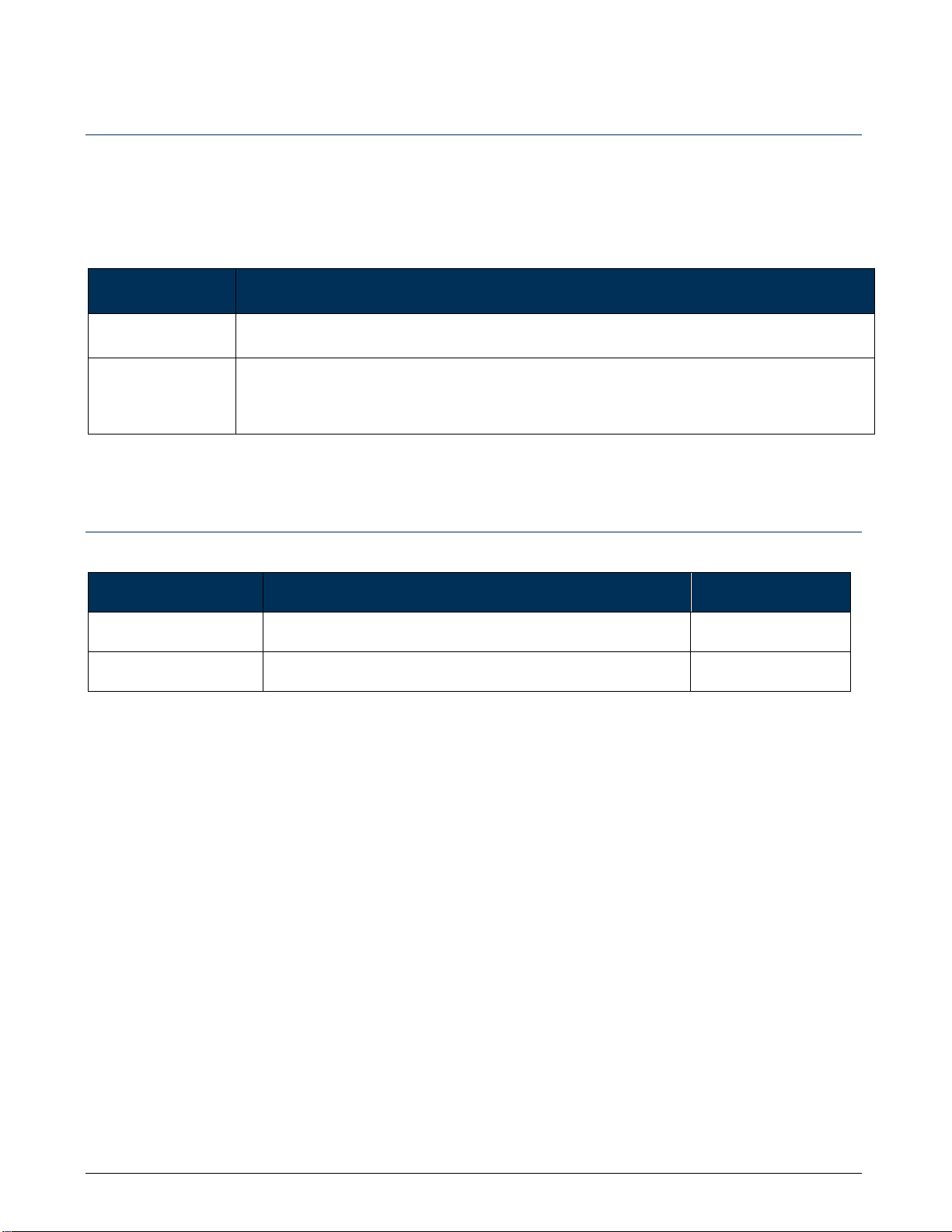
10 Parts and Accessories
Table 7: Spare parts for Auto Clean system
PRODUCT NAME
DESCRIPTION
PART NUMBER
Cleaning Fluid Bottle
1 Liter bottle for chemical fluid storage
25115
Chemical Pump Tubing
Replacement internal pump tubing for chemical pump
25120

Chemtrac UV Auto Clean - v 2.1
Chemtrac, Inc. 16
11 Cabinet Dimensions and Clearance
The front, side, and back views of the cabinet are shown below to the nearest 1/8 inch. The back view gives the
dimensions relevant for spacing of screws to mount the cabinet. Allow a clearance of 6 inches around the
cabinet for unit connection.

Chemtrac UV Auto Clean - v 2.1
Chemtrac, Inc. 17
12 Warranty
Chemtrac, Inc. warrants its equipment to be free from defects in material and workmanship for a period of one
(1) year from date of shipment to the original purchaser. Upon receipt of written notice from purchaser, seller
shall repair or replace the equipment (at option of Chemtrac, Inc.).
Chemtrac, Inc. assumes no responsibility for equipment damage or failure caused by:
1. Improper installation, operation, or maintenance of equipment.
2. Abnormal wear and tear on moving parts caused by some processes.
3. Acts of nature (i.e. lightning, etc.)
This warranty represents the exclusive remedy of damage or failure of equipment. In no event shall Chemtrac,
Inc. be liable for any special, incidental, or consequential damage such as loss of production or profits.
For further assistance or service please contact:
Chemtrac, Inc.
1555 Oakbrook Dr.
Suite 100
Norcross, GA 30093
Tel: 770-449-6233
Tel: 800-422-8722 (toll-free in US)
Fax: 770-447-0889
Email: chemtrac@chemtrac.com
Website: chemtrac.com
Table of contents


