Chemtrol Pyxis ST-730 Series User manual

1
ST-730 Series Inline
Turbidity Probe
Operation Manual
Version 1.2 August 2018

2
Table of Content
1. Introduction 3
2. Unpacking the Instrument 3
2.1. Standard Accessories 4
2.2. Optional Accessories 4
3. Specification 4
4. Installation 5
4.1. Quick 4-20 mA Start 6
4.2. Connect via WiFi/Bluetooth 6
4.3. Connect via USB 7
5. Probe Calibration with uPyxis Mobile App 7
5.1. Download uPyxis Mobile App 7
5.2. Connecting to uPyxis Mobile App 8
5.3. Diagnosis Screen 8
5.4. Calibration Screen and Reading 9
5.5. Device Info Screen 9
6. Probe Calibration with uPyxis Desktop App 10
6.1. Download uPyxis Desktop App 10
6.2. UnZip uPyxis Desktop App 11
6.3. Installing uPyxis Desktop App 12
6.4. Connecting to uPyxis Desktop App 13
6.5. Connecting to Device 14
6.6. Diagnosis Screen 15
6.7. Calibrating Device 15
6.8. Zero Calibration 16
6.9. Slope Calibration 16
6.10. 4-20 mA Span 17
7. Communicating using Modbus RTU 17
8. Probe Cleaning and Maintenance 17
8.1. Method to Clean ST-730 Series Probe 18
8.2. ST-730 Series Inline Probe Cleaning Solution 18
9. Other Common Troubleshooting Issues 19
10. Storage 19

3
1. Introduction
The Pyxis ST-730 series inline probe measures turbidity in water using a white LED as the excitation
light source and by measuring the scattered light at 90-degree angle with respect to the excitation
beam. The fluidic and optical arrangement of the ST-730 series probe is designed to overcome many
shortcomings associated with other inline turbidimeters. It can be easily inserted into the custom-
made tee with a compression fitting port designed to ensure correct positioning of the ST-730 series
probe in the fluid stream. The ST-730 series probe custom mounting tee has two ¾ inch female NPT
ports for plumbing into an existing ¾ inch sample water line. The ST-730 series probe can be
connected to any device that accepts an isolated or non-isolated 4-20mA input. The ST-730 series
probe has a short fluidic channel that can be easily cleaned. Other features of the Pyxis ST-730 series
probe include:
•Menu-driven calibration procedure using a computer connected via USB or WiFi. Any
formazin turbidity standard in the range of 10 to 400 NTU can be used for the calibration.
The standard can be the water sample itself when the turbidity value of the sample has
been measured by another turbidimeter that has been calibrated. This allows the ST-730
series probe to be calibrated without being removed from the system.
•Diagnostic information (probe fouling, color or turbidity over range, failure modes) can be
communicated to digital displays via Modbus RTU.
•The ST-730 series probe can be easily removed from the custom tee for cleaning without the
need or any tools.
2. Unpacking the Instrument
Remove the instrument and accessories from the shipping container and inspect each item for any
damage that may have occurred during shipping. Verify that all accessory items are included. If any
item is missing or damaged, please contact [email protected]
4
2.1. Standard Accessories
•Tee Set (tee, O-ring, and nut)
•Bulkhead Cable
•Operation Manual
2.2. Optional Accessories
•USB-RS485 Adapter (Item Number: MA-485)
•Bluetooth Adapter (Item Number: MA-485B)
•Pyxis Graphic Panel (Item Number: DC-200)
•1.5 inch OD O-ring (Item Number: MA-150)
•Extension cable –50 feet (PN:50705)
•Extension cable –100 feet (PN:5070)
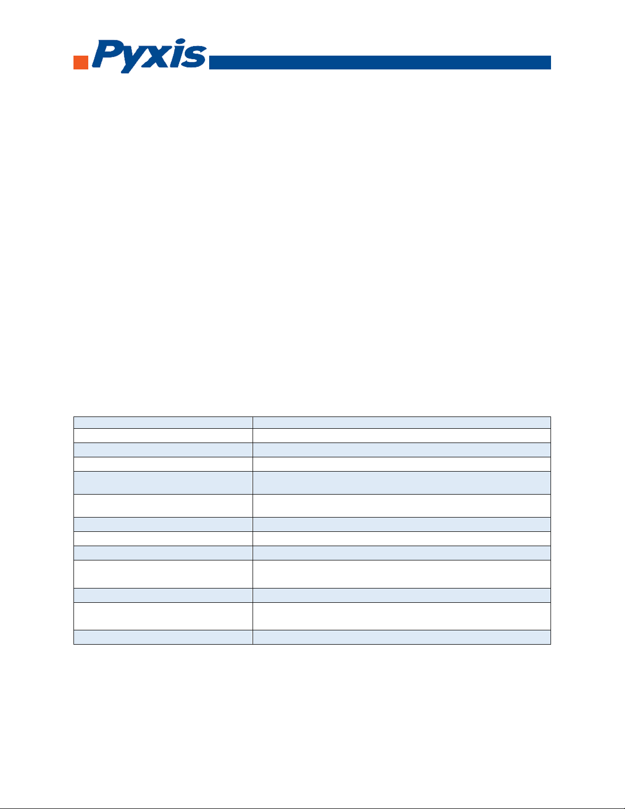
3. Specification
Items
Specification
Power Supply Required
24 (±2) VDC @ 65 mA
Signal Output
4-20 mA and RS-485 Modbus RTU
Sample Water Temperature
40 –104 °F (4 –40 °C)
Ambient Temperature During
Operation
40 –120 °F (4 –49 °C)
Ambient temperature During
Storage
20 –140 °F (-7 –60 °C)
Sample Pressure
100 PSI
Cable Length
5 feet, terminated with IP67 connectors
Water proof
Connector
Dimension
Length 6.8 inch (172.7 mm), body diameter 1.44 inch (36.6
mm)
Weight
0.37 pounds (170 grams)
Turbidity Range
2 to 500 NTU (3σ error: ±2 NTU or 5% of reading, whichever is
greater)
Regulatory
CE Marked

5
4. Installation
It is recommended to install the ST-730 series probe tee in the pipe system where sample water
flow is upwards. Place the O-ring on the ST-730 series probe. Insert the ST-730 series probe into the
tee. Make sure that the fluidic channel in the ST-730 series probe is aligned with the sample flow
direction.
ST-730 with Tee Set
ST-730 with Dimensions

6
4.1. Quick 4-20 mA Start
Note: The negative 24V power terminal (power ground) and the negative 4-20 mA terminal on the
ST-730 series probe are internally connected.
If the power ground terminal and the negative 4-20 mA terminal in the controller are internally
connected (non-isolated 4-20mA input), it is unnecessary to connect the 4-20 mA negative wire
(blue) to the 4-20 mA negative terminal in the controller. If a separate DC power supplier other than
that from the controller is used, make sure that the output from the power supply is rated for 22-26
VDC @ 65mA.
Follow the wiring table below to connect the ST-730 series probe to a controller.
Wire Color Designation
Red 24 V
Black Power ground
White 4-20 mA +
Green 4-20 mA - Internally connected to the power ground
Blue RS-485 A
Yellow RS-485 B
Clear Shield, solution ground
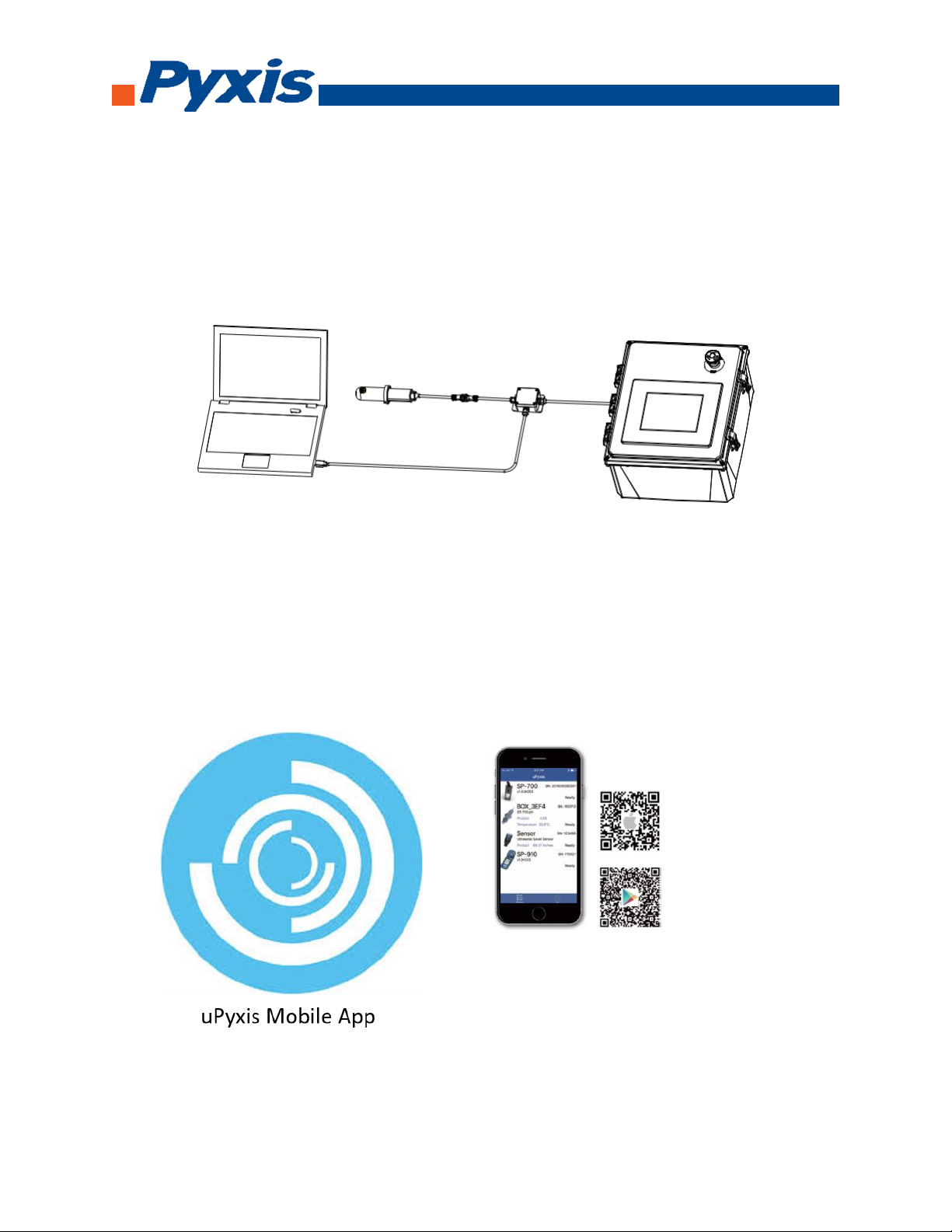
4.2. Connecting via WiFi/Bluetooth
The connection between a computer and the ST-730 series probe vis WiFi/Bluetooth adapter (P/N:
MA-WB). A smart phone app is provided to connect the ST-730 series probe to your smart phone
via WiFi/Bluetooth interface.
7
4.3. Connecting via USB
The connection between a computer and the ST-730 series probe via USB-RS485 adapter. Use the
USB-RS485 adapter provided by Pyxis Lab Inc. (Item Number: MA-485). Using other USB-485
adapters may result in permanent damage of the ST-730 series probe communication hardware.
5. Probe Calibration with uPyxis Mobile App
5.1. Download uPyxis Mobile App
Download uPyxis Mobile App from Apple App Store or Google Play
8
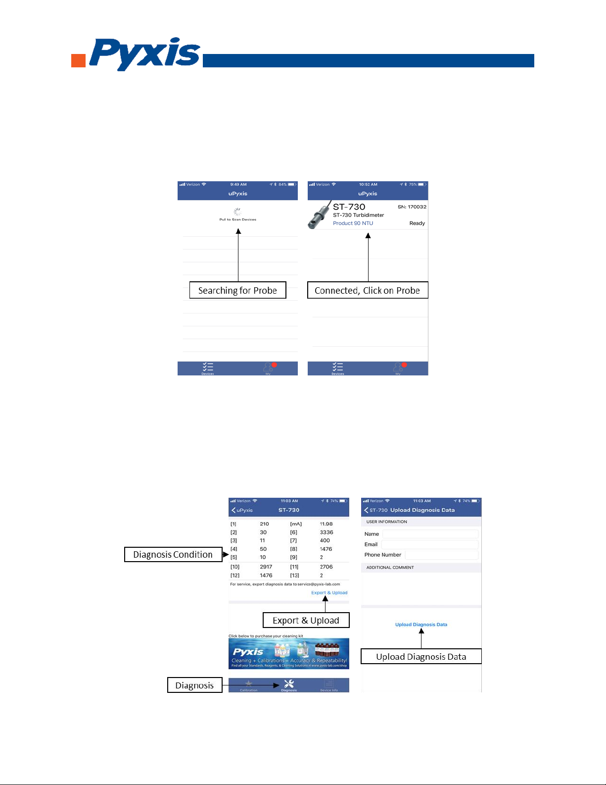
5.2. Connecting to uPyxis Mobile App
Turn on Bluetooth on your mobile phone (Do not pair the phone Bluetooth to the ST-730 series).
Open uPyxis Mobile App. uPxis App connects to the Probe and click on the ST-730 series probe.
5.3. Diagnosis Screen
From the Diagnosis screen. You can check the diagnosis condition and Export & Upload.

9
5.4. Calibration Screen and Reading
When connected, Mobile App will default to the Calibration screen. From the Calibration
screen you can perform calibrations by pressing on Zero Calibration, Slope Calibration,
and 4-20 mA Span. Follow the screen instructions for each calibration step.
5.5. Device Info Screen
From the Device Info screen. You can name the Device or Product.


11
6.2. UnZip uPyxis Desktop App
Find your downloaded uPyxis Setup 1.3.8 file, Right Click on the file, Extract All, and then
Extract.

12
6.3. Installing uPyxis Desktop App
Once the uPyxis Desktop App has been extracted. Find the extracted uPyxis Setup file and
left click, click on Run, and then click Install. After install has been clicked the Setup
Progress will continue. Follow the step during installation process.
13
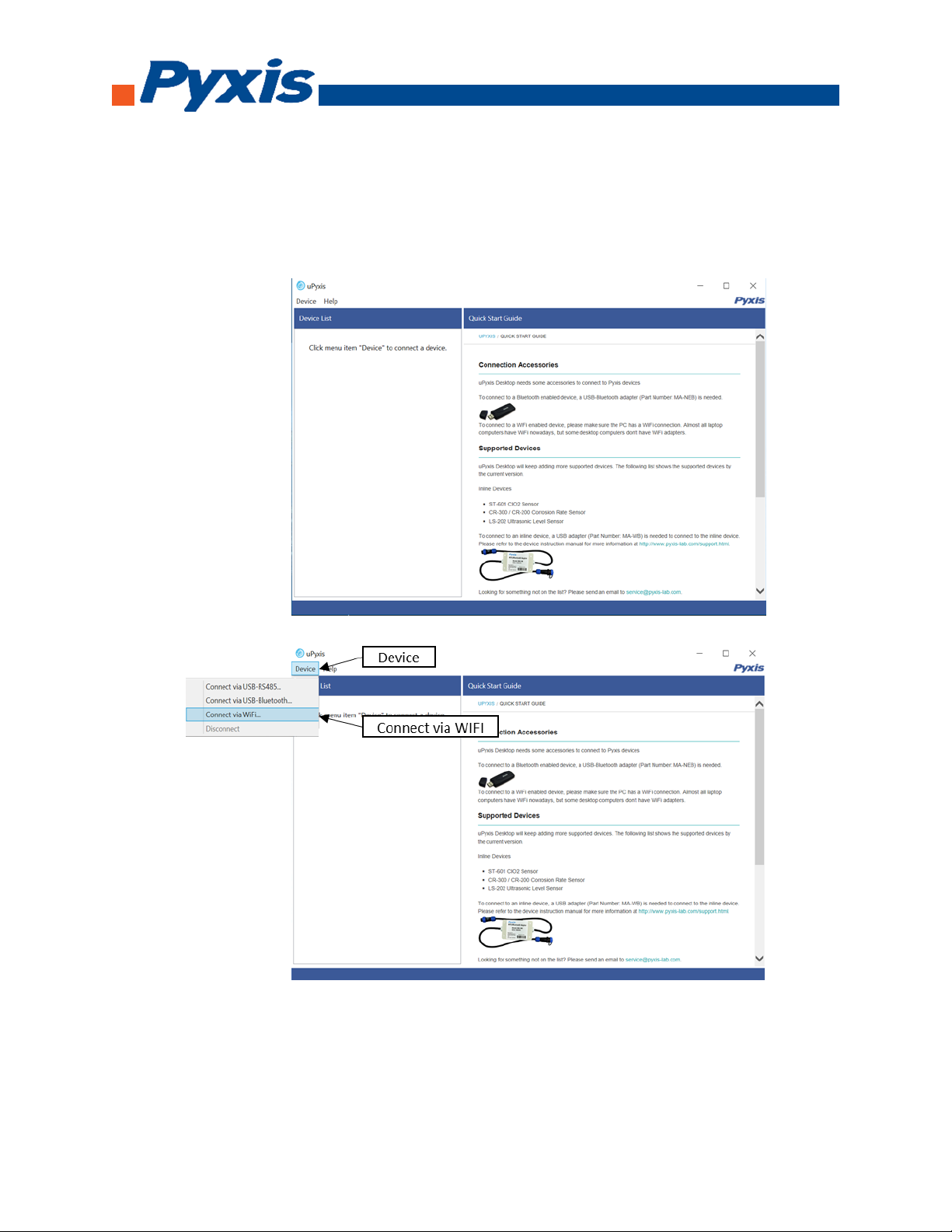
6.4. Connecting to uPyxis Desktop App
Open uPyxis Desktop App on your desktop. When the desktop app opens, to find your
device, click on Device, then Connect via WiFi.

14
6.5. Connecting to Device
When connected via WiFi, in the Discovered Devices box there will be the device product
name (If no device product name in the Discovered Devices box, click Refresh). If device
product name shows in the box, then click on Connect to Device. Once connected to the
device on the main screen a picture of the device will appear on the top left corner. On the
main screen you can set the information description for Device Name and Product Name,
then click Set to save.

15
6.6. Diagnosis Screen
After the device has been calibrated and installation has been completed. To check
diagnosis, click on Diagnosis. When in the Diagnosis screen you can view the Diagnosis
Condition of the device.
6.7. Calibrating Device
To calibrate the device, click on Calibration. On the Calibration screen there are three
calibration tabs, Zero Calibration, Slope Calibration, and 4-20 mA Span. The screen does also
display the reading of the device. The reading refreshed rate is every 4 seconds.

16
6.8. Zero Calibration
To perform Zero Calibration, click on Zero Calibration. Then follow the instruction on how
to calibrate, then click Ok.
6.9. Slope Calibration
To perform Slope Calibration, click on Slope Calibration. Then follow the instruction on
how to calibrate, then click Slope Calibration.

17
6.10. 4-20 mA Span
To perform 4-20 mA Span, click on 4-20 mA Span. Then follow the instruction on how
to calibrate, then click 4-20 mA Span.
7. Communicating using Modbus RTU
The ST-730 series probe is configured as a Modbus slave device. In addition to the NTU value, many
operational parameters, including warning and error messages, are available via a Modbus RTU
connection.
Contact CHEMTROL support for more information.
8. Probe Cleaning and Maintenance
When used to control product dosing, it is suggested that the automation system be configured to
provide backup to limit potential product overfeeds, for example by limiting pump size or duration,
or by alarming if the pumping rate exceeds a desired maximum limit.
The ST-730 series probe is designed to be easily removed, inspected, and cleaned if required. It is
suggested that the ST-730 series probe be checked for fouling and cleaned on a monthly basis.
Heavily contaminated waters may require more frequent cleanings. Cleaner water sources with less
contamination may not require cleaning for several months.

18
8.1. Methods to Cleaning ST-730 Series Probe
Any equipment in contact with industrial cooling systems is subject to many potential
foulants and contaminants. Our inline probe cleaning solutions below have been shown to
remove most common foulants and contaminants. A small soft bristle brush, Q-Tips cotton
swab, or soft cloth may be used to safely clean the probe housing and the quartz optical
sensor channel. Pyxis Lab Inline Probe Cleaning Solution Kit.
8.2. ST-730 Series Inline Probe Cleaning Solution
Soak the lower half of the ST-730 series probe in 100 ml inline probe cleaning solution for 30
minutes. Rinse the ST-730 series probe with distilled water and then check for the flashing blue
light inside the ST-730 series probe quartz tube. If the surface is not entirely clean, continue to
soak the ST-730 series probe for an additional 30 minutes.

19
9. Other Common Troubleshooting Issues
If the ST-730 series probe output signal is not stable and fluctuates significantly, make an additional
solution ground connection –connect the clear solution ground wire to a conductor that contacts
the sample water electrically such as a brass pipe adjacent to the ST-730 series tee.
Carry out routine calibration check against a turbidity standard. If necessary, carry out the zero
point and slope calibration.
10. Storage
Avoid long term storage at temperature over 100 °F. In an outdoor installation, properly
shield the ST-730 series probe from direct sunlight and precipitation.
Table of contents
Popular Measuring Instrument manuals by other brands

ATAGO
ATAGO PAL-26S instruction manual

Union Instruments
Union Instruments INCA5021 Translation of the original operating instructions

Digi-Pas
Digi-Pas DWL9000XY user manual

PCE Instruments
PCE Instruments PCE-PTR 200N user manual

Nidec-Shimpo
Nidec-Shimpo DT-2100 instruction manual

Meec tools
Meec tools 405-046 operating instructions


