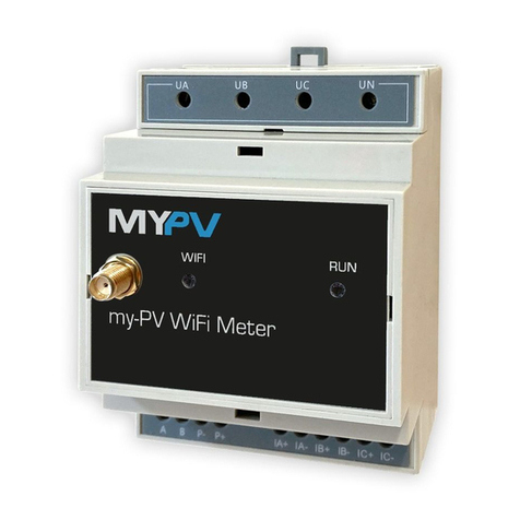
EMR iPM-1 Series User manual

MODEL SERIES iPM-1
RF POWER MONITOR
USER'S MANUAL
EMR CORPORATION
17431 N. 25th Avenue 85027- Phoenix, A izona
Tel: 623-581-2875 - Fax: 623-582-9499 - www.em .com - info@em .com

Table of Contents
Introduction 1
System Requirements 1
Getting Started 1
Programming the iPM-1 2
Bench Testing 10
Web Inter ace Access 12
Logging In 12
Viewing Current Readings and Alarms 12
Power Sensor and Alarm Setup 13
PTT Test Setup 15
PTT Sense Setup 16
COR Sense Setup 17
IP Setup 18
Email Setup 21
Date & Time Setup 23
Installation 24
Additional In o 28

17431 N. 25th Avenue - Phoenix, A izona 85023
Phone: (623) 581-2875 - Toll F ee: (800) 796-2875 - Fax: (623) 582-9499
info@em co p.com – www.em co p.com
Introduction
The iPM-1 is a WEB Based Mic op ocesso -cont olled unit. It p ovides monito ing of Fo wa d and Reve se RF
Powe of an RF T ansmitte , VSWR, PTT Line State and the COR output of a adio eceive . An output is also
p ovided to activate the T ansmitte 's PTT Line manually via the web page o automatically eve y hou .
Othe featu es include:
•P og amming using a standa d web b owse di ectly o ove LAN/WAN
• Use p og ammable ala m set points
◦High RF Powe
◦Low RF Powe
◦High VSWR
•1 Relay Output (t ips on any ala m)
•Passwo d Secu ed
•Powe and Ala m LEDs
•System Log
System requirements
1) EMR Model # 2491/T2 Powe Senso fo the f equency band desi ed.
2) EMR Model # CO8801A-PP-240 Powe Senso Cable.
3) Connection to a LAN/WAN o a C ossove Cable.
4) A standa d Web B owse .
5) 12 to 15 Vdc powe Supply.
etting started
Many of the iPM-1's featu es a e dependent upon the use ’s pa ticula situation. This documentation sta ts by
cove ing featu es that a e common to most use s.
It is assumed the installe has basic knowledge of IP and RF systems and the unit is to be installed to a VHF
Repeate at a Radio Site with Inte net access via an on site LAN. Also, the Accesso y Connecto has been p e-wi ed
(see Pg. 24, “Installation” section).
IMPORTANT! IF THE PTT LINE IS CONNECTED TO THE TRANSMITTER, TEMPORARILY DISCONNECT IT FROM THE
ACCESSORY CONNECTOR TO PREVENT INADVERTENTLY KEYIN THE TRANSMITTER UNTIL THE UNIT IS PRO RAMMED
CORRECTLY.
Befo e p og amming the iPM-1 you will need the following info mation f om you netwo k system administ ato :
1) Static IP Add ess and Sub Net Mask.
2) Gateway Add ess.
3) DNS Se ve IP Add esses (2 each).
4) Outgoing mail se ve (SMTP) not equi ing SSL and Po t numbe .
5) F om Email add ess, Use Name & Passwo d.
6) Up to 5 Email Add ess to eceive ala m notifications..
1

.
.
Programming the iPM-1 Power Monitor
Apply powe to the unit.
The iPM-1 is enti ely setup and cont olled f om a web b owse . The p efe ed method is to connect di ectly between
the IPM-1 and a compute using a c ossove cable on the bench befo e installing the unit in the field.
The iPM-1's default IP Add ess is set at 192.168.3.250. This will equi e that the compute used fo access has it's
IP add ess set to the same subnet (192.168.3.10, fo example).
Once connected via the C ossove Ethe net cable, load the web b owse and navigate to http://192.168.3.2 50 to
access the web page.
You will be p ompted fo a use name and passwo d (see Fig. 1).
Ente admin fo both the use name and the passwo d. Then click “OK”.
You will see the following sc een (see Fig. 2).
2
Fig. 1

17431 N. 25th Avenue - Phoenix, A izona 85023
Phone: (623) 581-2875 - Toll F ee: (800) 796-2875 - Fax: (623) 582-9499
info@em co p.com – www.em co p.com
To the left you will see the links to the following pages. With a b ief desc iption as follows:
Home
This is the main page used to view the RF Powe Fo wa d/Reve se eadings, VSWR Reading, Powe & VSWR
Ala m, COR and PTT States. Also Cha ts of Fo wa d/Reve se Powe and VSWR of the last 24 Readings (with Time
and Date) of the Powe Senso .
Power Sensor & Test PTT Setup
This page is fo ente ing setup info mation fo ala m set points, f equency, type of t ansmitte , enabling/disabling
ala m, PTT Test, PTT and COR Sense.
IP Setup
This page is fo ente ing setup info mation fo the IP add ess, Subnet Mask, Gateway, DHCP & DNS. Also Email
info mation, setting the Real Time Clock and changing the admin passwo d.
3
Fig. 2

.
.
View Log
This page will display the system Log of events.
We will assume you wish to have the following setup:
Sub Net: 255.255.255.0 Email Se ve : sma thost.xyz.com
Gateway Add ess: 192.168.100.1 Email Po t: 25
DNS Se ve #1: 208.200.23.20 Passwo d: q1234T
Email to: [email protected]
To continue with the setup p ocess click on IP Setup.
Ensu e that DHCP Se ve is disabled.
Now ente the IP Add ess, Subnet & Default Gateway info mation into the Static IP Address Setup table (Fig. 3).
Now click the Submit button to ente .
You will notice that the page did not eload into the b owse (see Fig. 4).
Since the new IP Add ess you ente ed is in a diffe ent g oup you must now change the IP add ess of you compute ,
In this example change it to 192.168.100.10.
4
Fig. 3

17431 N. 25th Avenue - Phoenix, A izona 85023
Phone: (623) 581-2875 - Toll F ee: (800) 796-2875 - Fax: (623) 582-9499
info@em co p.com – www.em co p.com
5
Fig. 4
Fig. 5

.
.
Now ente the new IP Add ess into the b owse , you will be p ompted fo the use name and passwo d again (see
Fig 5). You will now be back at the home page. Click on the IP Setup link to etu n to the setup page and ente the
DNS info mation (see Fig. 6) and click Submit.
Now ente in the Email Info mation (see Fig. 7) and click Submit.
Assuming that you have access to the 192.168.100.xxx LAN, you may now connect the iPM-1 and you compute to
the LAN fo testing the email. Do not fo get to set up the compute fo the LAN (If not, skip to setting the Real Time
Clock on the following page).
6
Fig. 6
Fig. 7

17431 N. 25th Avenue - Phoenix, A izona 85023
Phone: (623) 581-2875 - Toll F ee: (800) 796-2875 - Fax: (623) 582-9499
info@em co p.com – www.em co p.com
If you do not have access (i.e. the LAN is at a diffe ent location) the following will have to be pe fo med at the
installation site.
Test the email settings by selecting “1” f om the selection field next to the “Test Email” submit button (see Fig. 8).
If the test was successful, a message is displayed (see Fig. 9).
If the email failed, a message is also displayed (see Fig. 10).
Ente the GMT Time and Date. In the example below (Fig 11), the time is 17:00:09 and the Date is 08/02/2012. At
this time do not enable NIST Sync (this is best done once you have the unit in se vice). Next, select – o + and the
hou s diffe ent f om GMT and whethe o not Daylight Savings Time is obse ved. Then click the Submit button.
Note: This is a static web page. The time displayed is when the page was loaded.
7
Fig. 8
Fig. 9
Fig. 10
Fig. 11

.
.
Ente a new passwo d in the text box field (see Fig 12). It must be between 5 and 10 cha acte s. Then click the
Submit button.
Note: The User Name is always “admin” in lower case, and the password is case sensitive.
Now click on the Powe Senso & Test PTT Setup to view the page.
You will be p ompted fo a use name and passwo d (see Fig. 1). Ente admin fo the use name and the new
passwo d. Then click “OK”.
The Powe Senso & Test PTT Setup page can now be viewed.
It is assumed that this unit is to be installed to a VHF Repeate and that the installing technician has identified and
p e-wi ed the accesso y cable fo PTT, PTT Sense & COR Sense (see Fig. 17 and Fig. 37). Auto Test (key the
t ansmitte eve y hou to test) is also desi ed.
In this example, the PTT line equi es a TTL Low fo T ansmitting and the COR goes high when active.
Fi st, we will configu e the PTT Test Setup table.
Since the PTT line equi es a low to t ansmit, click on Hi in the P og am Output Table “Default State”. Also, enable
the featu e. Since auto test is desi ed, click “Y” unde Auto test. Set the Time Out Time to 5 Seconds (see Fig 13).
8
Fig 12
Fig 13

17431 N. 25th Avenue - Phoenix, A izona 85023
Phone: (623) 581-2875 - Toll F ee: (800) 796-2875 - Fax: (623) 582-9499
info@em co p.com – www.em co p.com
Now we need to configu e the PTT Sense Setup, since the PTT Line goes low to t ansmit click on Hi in the PTT
Active State table. Also Enable the featu e by clicking “Enabled” (see Fig 14). Debounce should be enabled if you
expe ience false eadings (usually not equi ed).
Next, we will configu e the COR Sense Setup.
In ou example, the COR line will go High when a ca ie is eceived, so click on “Hi” in the COR Active State table.
Also Enable the featu e by clicking “Enabled” (see Fig 15). Debounce should be selected if you expe ience false
eadings (usually not equi ed).
Click the “Submit” button to save these settings.
Finally, we will configu e the Power Sensor. Ente the F equency in the text box.
9
Fig 14
Fig 15

.
.
Leave the Ala m “Disabled” (we will test this late ). Set the High Powe ala m set point to “105” and the Low Powe
ala m set point to “75”. Hyste esis should be “5” fo both High and Low. Next set the VSWR to 2.00. Make su e
Continuous T ansmitte and Log RF Reading a e both “N”. Since we will be sending email to just one add ess check
the box labeled “1” in the Email Table (see Fig 16).
Note: The Frequency text Box is used for user identification only. It can also be a name (i.e. Ch. 1).
Bench Testing
The following desc iption is based on the iPM-1 being tested on the bench befo e actual installation to the Repeate
(see Fig 17 fo ecommended test setup). In ou example we a e using a 50 Watt Mobile Unit.
10
Fig 16
Fig 17

17431 N. 25th Avenue - Phoenix, A izona 85023
Phone: (623) 581-2875 - Toll F ee: (800) 796-2875 - Fax: (623) 582-9499
info@em co p.com – www.em co p.com
Connect the Power Sensor to the iPM-1 using the cable (EMR Model #CO8801A-PP-240) to the RJ-11-6
Connecto ma ked Di ectional Couple (see Fig 18).
The LCD display should now ead “0 FWD 0 REV”.
Using the compute log back on to the web page and view the home page.
Key up the t ansmitte and the RF powe should be displayed on the LCD Display and the home page. Also, VSWR
should change f om No Signal to a eading of the VSWR . Un-key the t ansmitte .
Note: There is latency on the home web page. Readings are delayed.
Next test the COR Sense by applying a high (5 Vdc) to the COR Sense line. The Reading should change f om “Off”
to “On”.
Now tie the PTT Test line and the PTT Sense line togethe and click on the PTT Test Submit Button on the web
Page. PTT Sense should change f om “Off” to “On”.
The final test will be an ala m test. Since in ou example we a e using a 50 Watt VHF t ansmitte we should get a
Low Powe Ala m since the Low Ala m Set point is set at 75 Watts.
Click on the Powe Senso & Test PTT Setup link on the left of the web page to view the page.
Enable the ala m by clicking on “Y” adio button in the ala m section of the Powe Senso table (see Fig 19) and
clicking on the Submit Button.
11
Fig. 18
Fig. 19

.
.
Retu n to the Home page by clicking on the Home link on the left of the page.
Key the t ansmitte until the ed Ala m LED is on then un key the t ansmitte .
The LCD display will ead “ALARM” momenta ily the then display “Low PWR 50 FWD”
The web page should also display an ala m (see Fig. 20).
Now clea the ala m by clicking the “Clea Ala m” submit button on the web page.
To check the Ala m Relay ope ation, connect an Ohm Mete o a Continuity test unit on pins 5 and 7 of the
accesso y connecto . T ip the ala m again by keying and unkeying the t ansmitte as desc ibed above. When in the
ala m state you should ead close to ze o ohms o continuity.
Now clea the ala m using the Ala m Reset located on the f ont panel. It will take two p esses to clea the ala m.
Web Interface Access
The iPM-1 is enti ely setup and cont olled f om the web. Once hooked up the netwo k via Ethe net cable navigate to
the default IP add ess to access the inte face. The default IP fo accessing the web inte face is:
http://192.168.3.250.
Logging In
Load the web b owse & navigate to the web page by ente ing the IP add ess of the unit in the URL to access the
web page. The use will be p ompted fo a use name and a passwo d. The Use Name is always “admin” and the
default passwo d is “admin”.
Viewing Current Readings and Alarms
The home page (see Fig. 21) p ovides an almost eal time display of the cu ent eadings of Fo wa d/Reve se
Powe , VSWR and Powe /VSWR Ala m status. Also, line cha ts of the last 24 eadings a e displayed fo Fo wa d/
Reve se Powe & VSWR.
Note: Charts are static and can be reloaded by clicking the “Re resh Chart” button.
If the accesso y output fo Push To Talk (PTT) is connected and p og ammed co ectly the use may click the “PTT
Test” button to key up the t ansmitte fo a use p og ammable time to test the t ansmitte emotely. Also PTT Sense
and COR (Ca ie on Receive) status is viewed he e.
12
Fig. 20

17431 N. 25th Avenue - Phoenix, A izona 85023
Phone: (623) 581-2875 - Toll F ee: (800) 796-2875 - Fax: (623) 582-9499
info@em co p.com – www.em co p.com
Power Sensor and Alarm Setup
By clicking on the Powe Senso & Tests PTT Link on the left f ame of the web page the Powe Senso & Tests PTT
page is displayed (see Fig. 22).
13
Fig. 21
Fig. 22

.
.
On the Power Sensor Table the Use can Ente /P og am the following;
Frequency:
Ente up to 8 cha acte s of the the f equency.
Note: The Frequency text Box is used for user identification only, it can also be a name (i.e. Ch. 1).
Display:
Check the LCD check box to display the Powe Senso eadings to the LCD Display Menu.
Check the HOME check box to display he Powe Senso eadings on the Home page.
Alarm:
Click the “Y” adio button to activate the ala m, o the “N” adio button to disable the ala m.
Audible Alarm:
Check this check box fo an audible ala m to sound f om the iPM-1.
Note: This check box is only displayed after Alarm check box = “Y” and has been submitted.
Continuous Transmitter:
Click the “Y” adio button if the unit is monito ing a Continuous T ansmitte . This will allow an ala m on “0”
RF Fo wa d Powe .
Log RF Readings:
Click the “Y” adio button if logging of any change of RF Powe is desi ed.
Click the “N” adio button to disable logging RF powe with the exception of Auto PTT Test Readings.
High RF Power Alarm Set Point:
This value sets the High RF fo wa d powe ala m set point.
Hysteresis:
This value sets the sensitivity of a High RF Ala m. “0” being the lowest and “255” the highest.
Inc ease this numbe in small inc ements if High RF false ala ms a e expe ienced.
Low RF Power Alarm Set Point:
This value sets the Low RF fo wa d powe ala m set point.
Hysteresis:
14

17431 N. 25th Avenue - Phoenix, A izona 85023
Phone: (623) 581-2875 - Toll F ee: (800) 796-2875 - Fax: (623) 582-9499
info@em co p.com – www.em co p.com
This value sets the sensitivity of a Low RF Ala m. “0” being the lowest and “255” the highest. Inc ease this
numbe in small inc ements if Low RF false ala ms a e expe ienced.
High VSWR Alarm Set Point:
This Value sets the High VSWR Ala m set point. Values should be ente ed to the second decimal.
Fo example “1.95”.
Email:
Select which of the Email Add esses ente ed on the IP page will be sent an email on an ala m by checking
any o all of the check boxes. Check box 1 co esponds with email add ess #1 up to email add ess #5. If
none a e checked, no email notifications will be sent.
PTT Test Set up
By clicking on the Powe Senso & Tests PTT Link on the left f ame of the web page the Powe Senso & Tests PTT
page is displayed (see fig. 22). PTT Test can be set up on the PTT Test Setup table (see Fig 23).
The Use can Ente /P og am the following;
Enable/Disable:
Click the “Y” adio button to enable the PTT Test Option.
Note: Only enable if the PTT Test Line is installed to the Transmitter.
Click the “N” adio button to disable the PTT Test Option.
Program Output:
Click the “Hi” adio button fo a TTL level High (5 Vdc) to be applied to the accesso y PTT Test line ( #11) in
the Default State (PTT=off).
Click the “Low” adio button fo a TTL level Low (0 Vdc) to be applied to the accesso y PTT Test line ( #11)
15
Fig. 23

.
.
in the Default State (PTT=off).
Time Out Timer Auto Test:
Time Out Timer
This value sets how long the PTT Test Line will become “active” in seconds afte the “PTT Test”
Submit Button has been clicked o an auto test is active. The default is 5 seconds, values a e 0 to
60 seconds.
Auto Test:
If the accesso y output fo Push To Talk (PTT) is connected and p og ammed co ectly the use may
use the Auto Test featu e. With this enabled the PTT Line is switched to the “active” state eve y hou
allowing the RF Powe to be sampled and VSWR calculated. If any of the Ala m Set points a e
eached the unit will ente the ala m mode and a Time Date stamped ent y of the ala m type is
ente ed to the Log.
Also, when this featu e is enabled, check boxes a e displayed in the email add ess that will
allow epo t eve y 24 hou s to be sent.
Click the “Y” adio button to enable the Auto Test featu e.
Click the “N” adio button to disable the Auto Test featu e.
PTT Sense Setup
By clicking on the Powe Senso & Tests PTT Link on the left f ame of the web page the Powe Senso & Tests PTT
page is displayed (see Fig. 22). PTT Sense can be set up on the PTT Sense Setup table (see Fig 24).
The Use can Ente /P og am the following;
Enable/Disable:
Click the “Y” adio button to enable the PTT Test Option.
Note: Only enable if the PTT Sense Line is installed.
Click the “N” adio button to disable the PTT Test Option.
16
Fig. 24

17431 N. 25th Avenue - Phoenix, A izona 85023
Phone: (623) 581-2875 - Toll F ee: (800) 796-2875 - Fax: (623) 582-9499
info@em co p.com – www.em co p.com
PTT Active State:
Click the “Hi” adio button if a TTL level High (5 Vdc) signals the PTT is active.
Click the “Low” adio button if a TTL level Low (0 Vdc) signals the PTT is active.
Debounce:
Debounce should be selected if you expe ience false eadings (usually not equi ed).
Click the “Y” adio button to enable Debounce.
Click the “N” adio button to disable Debounce.
COR Sense Setup
By clicking on the Powe Senso & Tests PTT Link on the left f ame of the web page the Powe Senso & Tests PTT
page is displayed (see Fig. 22). COR Sense can be set up on the COR Sense Setup table (see Fig 25).
The Use can Ente /P og am the following;
Enable/Disable:
Click the “Y” adio button to enable the COR Test Option.
Note: Only enable if the COR Sense Line is installed.
Click the “N” adio button to disable the COR Test Option.
COR Active State:
Click the “Hi” adio button if a TTL level High (5 Vdc) signals the COR is active.
Click the “Low” adio button if a TTL level Low (0 Vdc) signals the COR is active
17
Fig. 25

.
.
Debounce:
Debounce should be selected if you expe ience false eadings (usually not equi ed).
Click the “Y” adio button to enable Debounce.
Click the “N” adio button to disable Debounce.
IMPORTANT! Make sure to click on the “Submit” button on the bottom of the page to save any changes.
IP Setup
By clicking on the IP Setup Link on the left f ame of the web page the IP Setup page is displayed (see Fig. 26).
The Use can Ente /P og am the following:
Unit Name:
The unit name is fo convenience of the use . It is used to identify the unit and can be any text up to 50
cha acte s in length. Clicking the “Submit“ button below this table will save any changes made.
Network Connection Details:
18
Fig. 26
Table of contents
