CHESTER 812 User manual


IMPORTANT
SAFETY FIRST
ALL MACHINES ARE DANGEROUS
1. Use the correct tool for the job at hand never make a machine do a job it was not designed
for.
2. Never force the tool in the machine it will do the quicker and safer at the correct rate.
3. Always use clamps or vices to secure work – your hand is not strong enough!
4. When changing tools or work pieces always disconnect the machine first.
5. Service the machine regularly; a correctly operating machine is a safer machine.
6. Always replace belt covers before starting the machine.
7. Understand the machine fully before operation and always read the manual.
8. Get to know the machines limitations and applications.
9. Ensure that the machine is securely bolted to the bench and that the bench is securely
bolted to the ground.
TAKE GREAT CARE WHEN OPERATING THIS MACHINE TO PROTECT
YOUR BODY
1. Always wear safety glasses – everyday glasses are not suitable.
2. Dust can be caused when machining certain materials, always wear a mask.
3. Make sure you are not wearing any loose clothing such as ties, rings, bracelets that may get
caught in the moving parts of the machine.
4. Keep a proper footing and balance whilst operating the machine.
5. Never leave cleaning rags, etc on or near the machine.

SAFETY FIRST
ELECTRICS
1. All electrical tools must be earthed.
2. Never use electrical tools in damp or wet environment.
3. Make sure the machine is in the off position before switching on at the mains.
4. Always immobilise the machine before servicing or setting up work in the machine.
5. Great care should be taken when using coolant fluid with machine tools.
6. Ensure the machine is correctly connected and a fuse of the proper rating is used.
CHILDREN
1. Keep children away from machines, if necessary fit safety locks to the machine and mains
switches.
2. Never use machinery whilst talking to visitors, always concentrate on the job in hand!
REMEMBER ALL MACHINES
ARE
DANGEROUS IF NOT
USED CORRECTLY!

CONTENTS
1. General Guidelines for Use..........................................................................................4
2. Specification..................................................................................................................7
3. Delivery & Installation..................................................................................................7
4. Minimum Space for Machine Operation.....................................................................8
5. Tooth Selection.............................................................................................................8
6. Bi-Metal Speeds & Feeds............................................................................................10
7. Telltale Chips...............................................................................................................11
8. Assembly.....................................................................................................................11
9. Operation....................................................................................................................12
10. Blade Guide Bearing Adjustment..............................................................................17
11. Trouble Shooting........................................................................................................18
12. Circuit Diagram...........................................................................................................19
13. Part Diagrams & Part List...........................................................................................21

GENERAL GUIDELINES FOR USE
As with all machinery there are certain hazards involved with the operation and use of the
bandsaw. Using the machine with respect and caution will considerably lessen the possibility
of person injury. However, if normal safety precautions are overlooked or ignored, personal
injury to the operator may result.
This machine was designed for certain applications only. We strongly recommend that the
machine is not modified, and / or used for any application other than which it was designed. If
you have any questions relative to its application do not use the machine, until you
have first been in contact with the supplier or manufacturer.
The bandsaw may not arrive with a power socket or plug. In the event of this happening,
please inform Chester UK on Tel: (01244) 531 631.
SAFETY RULES FOR ALL TOOLS
USER
1. Wear correct apparel
No loose clothing, gloves, rings, bracelets or other jewellery to get caught in moving
parts. Non-slip footwear is recommended. Wear protective hair covering to contain long
hair.
2. Always wear eye protection
Refer to ANSLZ87.1 standard for appropriate recommendations. Also use face and / or a
dust mask if the cutting operation is dusty.
3. Don’t overreach
Keep a proper footing and balance at all times.
4. Never stand on a tool
Serious injury could occur if the tool is tipped or if the cutting tool is accidentally
contacted.
5. Never leave the tool running unattended
Turn power off. Leave tool until it comes to a complete stop.
6. Drugs, alcohol and medication
Do not operate the tool while under the influence of drugs, alcohol or any medication.
7. Make sure the tool is disconnected from the power supply
While motor is being mounted, connected or reconnected.
8. Always
Keep hands and fingers away from the blade.
9. Stop
The machine before moving chips.
10.Shut-off
Power and clean the bandsaw and work area before leaving the machine.
USE OF THE MACHINE
1. Remove adjusting keys and wrenches
Form a habit of checking to see that keys and adjusting wrenches are removed from the
tool before turning it ‘on’.
2. Don’t force the tool
It will do the job better and be safer at the rate for which it was designed.
3. Use the right tool
Don’t force the tool or attachment to do a job for which it was not designed.

4. Secure work
Use clamps or a vice to hold work when practical. It’s safer than using your hands, and
frees both to operate the machine.
5. Maintain tools in top condition
Keep tools sharp and clean for the best and safest performance. Follow instructions for
lubricating and changing accessories.
6. Use recommended accessories
Consult Chester UK for recommended accessories. The use of improper accessories
may cause hazards.
7. Avoid accidental starting
Make sure the switch is in the ‘OFF’ position before plugging in power cord.
8. Direction of feed
Feed work into a blade or cutter against the direction of rotation of the blade or cutter
only.
9. Adjust and position
The blade guide arm before starting the cut.
10. Keep the blade guide arm tight
A loose blade guide arm will affect the sawing accuracy.
11. Make sure
The blade speed is set correctly for material being cut.
12. Check
For proper blade size and type.
13. Stop
The machine before putting material in the vice.
14. Always
Have stock firmly clamped in the vice before starting the cut.
15. Ground all tools
If the tool is equipped with a three-prong plug, it should be plugged into a three-hole
electrical receptacle. If an adapter is used to accommodate a two-prong receptacle, the
adapter plug must be attached to a known ground. Never remove the third prong.
ADJUSTMENT
Make all adjustments with the power off. When assembling follow the manuals
instructions, this will ensure correct instruction and a safe structure.
WORKING ENVIROMENT
1. Keep the work area clean
Cluttered areas and benches invite accidents.
2. Don’t use in a dangerous environment
Don’t use power tools in damp or wet locations, or expose to rain. Keep the work area
well lit.
3. Keep children etc at a safe distance.
All children etc should be kept at a safe distance from the work area.
4. Don’t
Install & use this machine in an explosive dangerous environment.

MAINTENANCE
1. Disconnect
Machine from the power source when making repairs.
2. Check damaged parts
Before further use of the tool, a guard or other part that is damaged should be carefully
checked to ensure that it would operate properly and perform its intended function
check for alignment of moving parts, binding of moving parts, breakage of parts,
mounting and any other conditions that may affect its operation. A guard or other part
that is damaged should be properly repaired or replaced.
3. Disconnect tools
Before servicing and when changing accessories such as blades bits, cutters, etc.
4. Make sure
That the blade tension and blade tracking are properly adjusted.
5. Re-check
Blade tension after the initial cut with a new blade.
6. To prolong the blade life
Release the blade tension at the end of each working day.
7. Check the coolant level daily
A low coolant level can cause foaming and a high blade temperature. Dirty or weak
coolant can clog the pump, cause a crooked cast, low cutting rate and permanent blade
failure. Dirty coolant can cause the growth of bacteria with ensuing skin irritation.
8. When cutting magnesium never
Use soluble oils or emulsion (oil-water mix) as water will greatly intensify any accidental
magnesium chip fire. See your industrial coolant supplier for specific coolant
recommendations when cutting magnesium.
9. To prevent
The corrosion of machined surfaces when a soluble is used as coolant, pay particular
attention to wiping dry the surfaces where fluid accumulates and does not evaporate
quickly, such as between the machine bed and vice.
SPECIFIED USAGE
The machine is used only for general metals cutting within the range of cutting capacity.
NOISE
A weighted sound pressure level: 80 dB.
SAFETY DEVICE
1. Interlock switch on pulley cover. As soon as the pulley cover is open, the machine
will come to a stop with the function of this switch. Do not remove this switch from
the machine for any reason, and check it’s function frequently.
2. Interlock switch on cutting area. As soon as the pulley cover is open, the machine
will come to a stop with the function of this switch. Do not remove this switch from
the machine for any reason, and check it’s function frequently.
SPECIFICATION
Motor
0.55KW (3/4HP), 1HP (Option)
Blade Size
19.05 x 0.8 x 2362 (Carbon Blade)
60Hz
(FPM)
98 164 246 328
121 197 265
Saw Blade
(MPM)
29 50 75 100
37 60 81
Speed
50Hz
(FPM)
81 135 203 270
101 164 220
(MPM)
24 41 61 82
31 50 67
Model No. Cutting Capacity
812
812N
812G
90º
Ο (mm)
200 (8")
(mm)
178 x 305 (7" x 12")
Ο (mm)
127 (5")
45º
(mm)
120 x 125
(4 3/4" x 4 7/8")
Dimension LxWxH (mm)
1235 x 430 x 1100
N.W. / G.W. (kgs)
110 / 130
120 / 145
145 / 170
Packing Measurement
LxHxW (mm)
1270 x 470 x 1140
DELIVERY & INSTALLATION
UNPACKING
1. Transport to the desired location before unpacking, use lifting a lifting jack (Fig. B).
2. Transport after unpacking; please use a heavy-duty fibre belt in order to lift the
machine.
FIG. B
TRANSPORT RECOMMENDATIONS
1. Tighten all locks before operating.
2. Always keep a proper footing & balance while moving the bandsaw.
3. Disconnect the power supply, and make sure the machine is properly grounded.
4. Check the blade making sure that it is running in a counter-clockwise direction
5. Keep the bandsaw out of direct sunlight, dust, wet or water.
INSTALLATION
1. The saw may be mounted on a work bench or stand using six bolts.
2. The rear end of the base must be mounted on the rear of the stand or bench to
permit the vertical operation for this bandsaw.

INSTALLATION STEPS FOR THE PLASTIC COVER
1. Open the plastic moulded belt cover. Inlay the left indentation to the bottom of the
pulley. If the gap is too small, loosen the fixing screws of the pulley, then, move the
pulley out slightly.
2. Turn the belt cover counter clockwise, set the indentation into the pulley. Then
adjust the pulley until correct.
3. Set the indentation completely into the pulley, and then adjust the pulley until level
with the surface. You can now fix all the related screws into place.
MINIMUM ROOM SPACE FOR MACHINE OPERATION
TOOTH SELECTION
For maximum cutting efficiency and lowest cost per cut, it is important to select the blade with
the right number of teeth per inch (TPI) for the material being cut. The material size and shape
dictate tooth selection.
You need to consider:
1. The width of the cut. That is, the distance in the cut that each tooth must travel from
the point it enters the work piece until it leaves the work piece, and
2. The shape of the work piece.
•Squares, Rectangles, Flats (Symbol:
∎
)
Locate the width of the cut on the chart (inches on the outer circle and millimetres on the
inner circle). Select the tooth pitch

TOOTH SELECTION
on the ring marked with the square shape which aligns with the width of cut.
EXAMPLE: 6” (150mm) square, use a 2/3 Vari-Tooth.
•Round Solids (Symbol: ●)
Locate the diameter of your work piece on the chart. Select the tooth pitch on the ring marked
with the round shape that aligns with the size of stock you are cutting.
EXAMPLE: 4” (100mm) round, use a ¾” Vari-Tooth.
•Tubing, Pipe, Structural (Symbol: O H
^
)
Determine the average width of cut by dividing the area of the work piece by the distance the
saw blade must travel to finish the cut. Locate the average width of the cut on the chart, then,
select the tooth pitch on the ring marked with the tubing and structural shape. This aligns with
the average width that you are cutting.
EXAMPLE: 4” (100mm) outside diameter, 3” (75mm) inside diameter of the tubing.
4” (100mm) OD = 12.5 sq.in (79cm2)
-3” (75mm) ID = 7.0 sq.in. (44cm2)
Area = 5.5 sq.in. (35cm2)
5.5 sq.in. (35cm2) / 4” (100mm)
distance = 1.38 (35mm) average width
1.38” (35mm), use a 4/6 Vari-Tooth
Note: The band speed and cutting rate recommendations presented on this chart are
approximations and are meant to be used as a starting point for most applications. For exact
cutting parameters consult a saw blade supplier.

BI-METAL SPEEDS AND FEEDS
These figures are a guide to cutting 4” (100mm) material (with a 314 Vari-Tooth) when using a
cutting fluid.
Increase Band Speed: 15% When cutting ¼” (6.4mm) material (10/14 Vari-Tooth)
12% When cutting ¾” (19mm) material (6/10 Vari-Tooth)
10% When cutting 1-1/4” (32mm) material (5/8 Vari-Tooth)
5% When cutting 2-1/2” (64mm) material (4/6 Vari-Tooth)
Decrease Band Speed: 12% When cutting 8” (200mm) material (2/3 Vari-Tooth)
MATERIAL
ALLOY
ASTM NO.
BAND
SPEED
MATERIAL
ALLOY
ASTM NO.
BAND
SPEED
FT. / MIN
M / MIN
FT. / MIN
M / MIN
Cooper
173,932
314
96
Ni-Cr-Mo
8615, 8620,8622
239
73
Alloy
330,365
284
87
Alloy Steel
8640
199
61
623,624
264
81
E9310
174
53
230,260,272
244
74
280,264,632,655
244
74
Tool Steel
A-6
199
61
101,102,110,122,
234
71
A-2
179
55
172
D-2
90
27
1751,182,220,51
234
71
H-11, H-12, H-13
189
58
0
625,706,715,934
234
71
Stainless
420
189
58
630
229
70
Steel
430
149
46
811
214
65
410, 502
140
43
414
115
35
Carbon
1117
339
103
431
95
29
Steel
1137
289
88
440C
80
24
1141, 1144
279
85
304, 324
120
36
1141 HI
279
85
304L
115
35
STRESS
347
110
33
1030
329
100
316, 316L
100
30
1008, 1015, 1020,
319
97
416
189
58
1025
1035
309
94
1018, 1021, 1022
299
91
1026, 1513
299
91
A36 (SHAPES), 1
269
82
,040
1042, 1541
249
76
1044, 1045
219
67
1060
199
61
1095
184
56

TELLTALE CHIPS
Chips are the best indicator of correct feed force. Monitor the chip formation and adjust feed
accordingly.
Thin or powdered chips – increase the feed rate or reduce the band speed.
Burned heavy chips – reduce the feed rate and / or band speed.
Curly silvery and warm chips – optimum feed rate and band speed.
ASSEMBLY
A ¾ H/P, motor, split phase or capacitor-start it recommended for best economical
performance. A counter clockwise rotation is required. Note, that following the directions
given on the terminal or nameplate can reverse the rotation.
1. Assemble the motor Mounting plate to the head using the long bolt. Note the flat
side of the plate faces up.
2. Assemble the guard plate to the head using the screw and Lock Washer. The
Carriage Bolt Washer and Wing Nut are used to secure the Motor Mounting Plate to
the Guard Plate, through the slotted hole in the Guard Plate. These components also
serve to position and lock the motor, this will achieve a correct speed / belt
adjustment.
3. Place the spacer over the Long Bolt and secure it with the nut.
4. Secure the Motor to the Motor Mounting Plate with four bolts and nuts. Note that
the Motor Shaft is placed through the large opening in the Guard Plate, and that it
must be parallel with the Drive Shaft.
5. Assemble the Motor Pulley (the smaller of the two provided) to the Motor Shaft.
Note that the larger diameter must be closest to the motor. Do not tighten the set
screw.
6. Assemble the Driven Pulley (the larger of the two provided) to the protruding Drive
Shaft. Note the small diameter must be the nearest to the bearing.
7. Place the belt into one of the pulley grooves, and the other end into the respective
grooves of the second pulley.

8. Line up the belt and both pulleys (such that the belt is running parallel in the pulley
grooves.
9. Tighten the setscrews of both pulleys in this position.
10. Place the belt into a pulley combination for a correct blade speed (see material cut.
chart).
11. Adjust the position of the Motor to obtain approximately ½” depression in the belt
when applying pressure with your thumb.
12. Tighten the head screw holding the Motor Mounting Plate to the Guard Plate.
13. Connect the Electrical Harness to the Motor Terminal Box. The Motor should be
protected with a time delay fuse or circuit breaker with related amperage slightly
greater than the full load amperage of the motor.
OPERATION
WORK SET UP
1. Raise the saw head to vertical position.
2. Open vice to accept the Piece to be cut by rotating the wheel at the end of the base.
3. Place work piece on the saw bed. If the piece is long, support the end.
4. Clamp the work piece securely in the vice.
WORK STOP ADJUSTMENT
1. Loosen the thumbscrew holding the work stop casting to the shaft.
2. Adjust the work stop casting to the desired length position.
3. Rotate the work stop, as to close to the bottom of the cut as possible.
4. Tighten thumbscrew.
5. DO NOT ALLOW the blade to rest on the work while the motor is shut off.
BLADE SPEEDS
When using your Band saw always change the blade speed to best suit the material
being cut. The material cutting sheet gives suggested settings for several materials.
Material Speed (MPM)
50Hz 60Hz
Tool, Stainless, Alloy Steel,
24 MPM
29 MPM
Bearing Bronze
Medium to High Carbon Steels, 41 MPM 50 MPM
Hard Brass or Bronze
Low to Medium Carbon Steel 61 MPM 75 MPM
Soft Brass
Aluminium,
Plastic
82 MPH
100 MPH
MANUAL GEAR TYPE SPEED CHANGING
1. Select the proper cutting speed according to the material of work-pieces, and use
the blade selection chart.
2. Turn the speed-changing handle, for the necessary speed.
3. DO NOT change the speed during cutting.
4. Alter the speed when the bandsaw is at a complete stop.
5.
Note:
The oil of the gearbox is between 950cc ~ 1000cc.
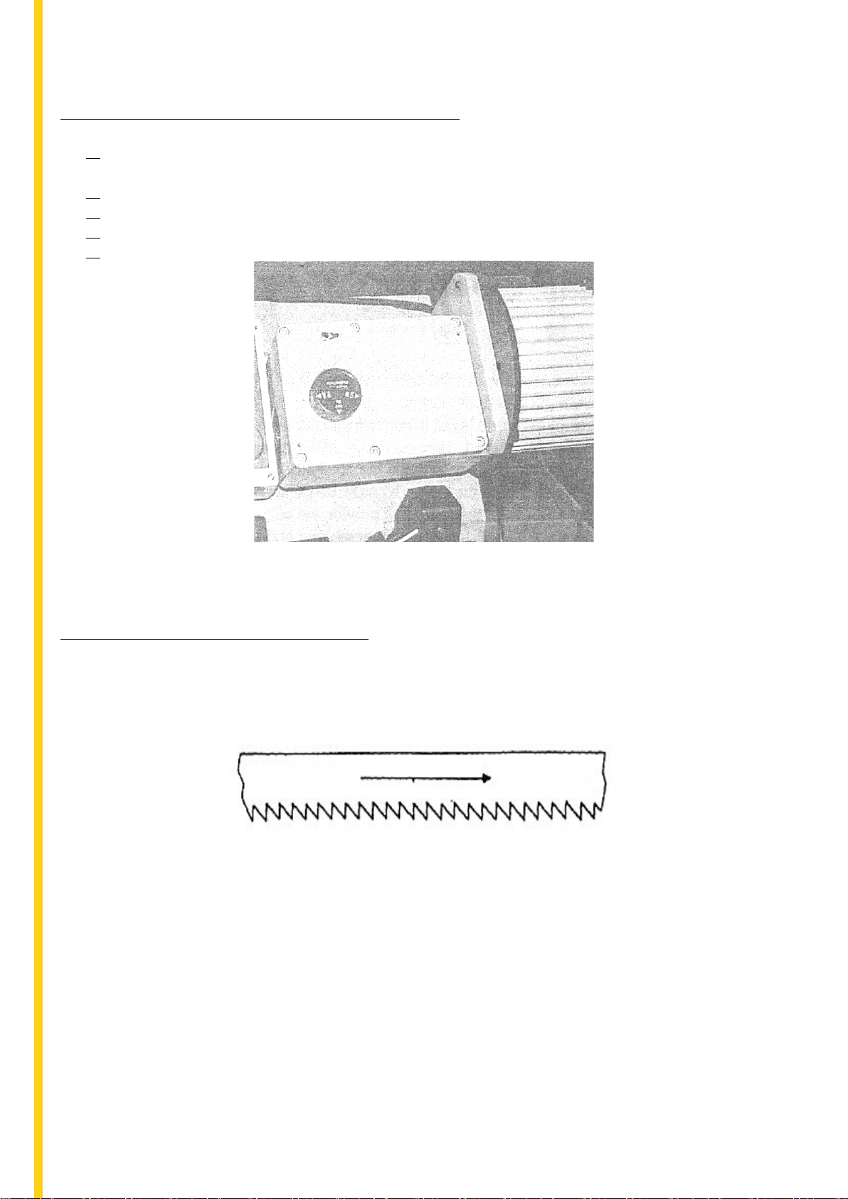
DIRECTION OF BLADE TRAVEL
Make sure the blade is attached to the pulleys, so that the vertical edge engages the
work piece.
BLADE MOVEMENT.
Blade Direction

STARTING SAW
Switch button function description (FOR CE ONLY)
CAUTION:
Never operate the bandsaw without the guards in position. Make sure the blade is not in
contact with the work when the motor is started. Start the motor, allow the saw to reach full
speed, then you can begin the cut by letting the head down slowly onto the work. Don’t drop
or force. Let the weight of the saw head provide the cutting force. The saw automatically shuts
off at the end of the cut.
BLADE SELECTION
An 8-tooth per inch general use blade is comes fitted to the bandsaw, additional blades
in 4, 6, 10, 14 and 18 tpi are available. The choice of the blade pitch is governed by the
thinness of the work that is to be cut.
In general, the thinner the work piece, the more teeth are required. A number of three teeth
should engage the work piece at all times for proper cutting. If the teeth of the blade are far
apart, so that they straddle the material, will cause damage and will affect the end result.
CHANGING BLADE
Raise the saw head to a vertical position and open the blade guards. Loosen the tension
screw knob sufficiently to allow the saw blade to slip off the wheels. Install the new blade with
teeth slanting toward the motor as follows:
1. Place the blade in between each of the guide bearings.
2. Slip the blade around the motor pulley (bottom) with the left hand and hold in
position.
3. Hold the blade taut against the motor pulley by pulling the blade upward with the
right hand. This should be placed at the top of the blade.
4. Remove your left hand from the bottom pulley, and place at the top of the blade to
continue the application on the upward pull on the blade.
5. Remove your right hand from the blade and adjust the position of the top pulley.
This will permit the left hand to slip the blade around the pulley using the thumb,
index and little finger as guides.
6. Adjust the blade tension knob clockwise until it is in the correct position, so that no
blade slippage occurs. Try not to tighten excessively.
7. Replace the blade guards.
8. Place 2-3 drops of oil on the blade.
HOW TO USE THE CHUCK VICE
1 2
3

1. The position of the vice when tightened.
2. The position of the vice when loosened (completely opened).
3. The position of the vice when loosened (half opened).
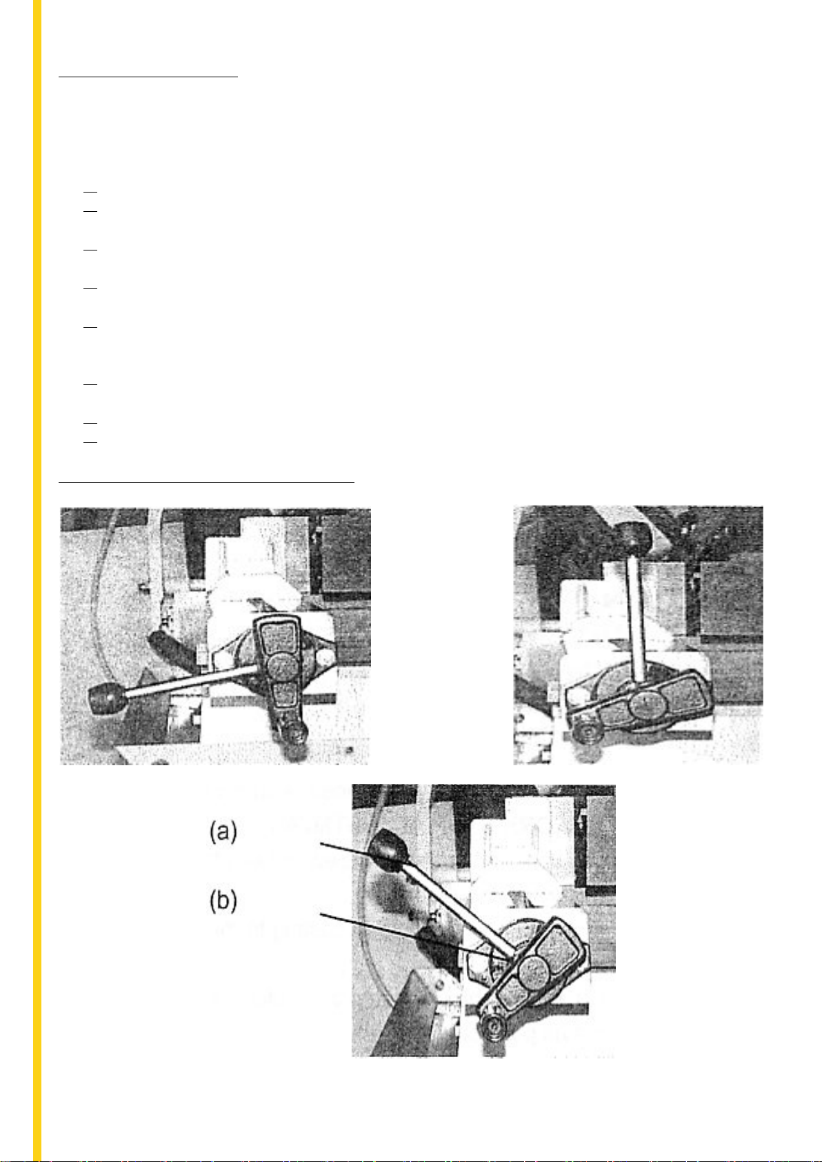
TRU-LOCK VICE SYSTEM INSTRUCTIONS
To operate, follow the below instructions:
1. Raise the arm 2” above the work piece, and then close the cylinder valve. Doing this
will keep the arm stationary.
2. Put your work piece on the table. Move the vice handle (a) upwards to 45 degree
angle (half open) to loosen the vice. Move the vice jaw bracket against the work
piece by turning the rectangular handle (b). Push down on the vice handle (a) to lock
the work piece in position.
3. To loosen the work piece from the vice, hold the work piece and lift the handle (a) to
a 90-degree position (completely opened). Then the work piece can be removed.
CONTINUED CUTTING
When you need to cut your work piece allot, raise the vice handle (a) to loosen and adjust
the position. Then you can push down on the same handle to tighten.
You can also push the vice handle (a) down first, and then tighten by turning the
rectangular handle (b) clockwise. After finishing the cut, you can loosen the work piece by
turning the rectangular handle.
This Tru-Lock Vice System has a 3mm tightening the travel when the rectangular handle is
completely opened. There is only a 1mm tightening travel necessary for normal metal
materials. The operator can tighten the work piece by pushing down the vice handle (a)
with a certain amount of pressure, depending on the hardness of the work piece.
A QUICK VICE ADJUSTMENT FOR A ANGLE CUT
1. Loosen the A, B, C and D screw.
2. Adjust the rear vice to the threaded hole position (E).
3. Set the scale to the desired angle.
4. Adjust the front vice (F) to parallel the rear vice (E)
5. Tighten the A, B, C and D screw.
BLADE GUIDE BEARING ADJUSTMENT
This is the most important adjustment on the saw. It is impossible to get satisfactory
work from the saw if the blade guides are not properly adjusted. The blade guide bearings on
your metal cutting band saw are adjusted and power tested with several test cuts before
leaving the factory. The need for adjustment should rarely occur, providing the saw is used
correctly.
If the guides do require adjustment, it is advisable to correct immediately. An incorrect
adjustment will make the blade not cut straight, and if it is left to continue it will cause serious
blade damage. Guide adjustment is a critical factor in the performance of the saw.
It is always advisable to try a new blade, to see if this corrects poor cutting, before you begin
to adjust. If a new blade does not correct the problem, check the blade guides for a correct
spacing.
NOTE: There should be from 000 (just touching) 001 clearance between the blade and guide
bearings to obtain this clearance. Adjust as follows:
1. The inner guide bearing is fixed and cannot be adjusted.
2. The outer guide bearing is mounted to an eccentric bushing and can be adjusted.
3. Loosen the nut while holding the bolt with an Allen wrench.
4. Position the eccentric by turning the bolt to the desired position of clearance.
5. Tighten the nut.
6. Adjust the second blade guide bearing in the same manner.
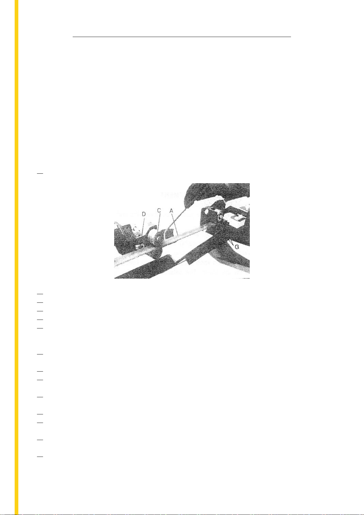
Remark:
1. Adjust the tension of the blade until the back of the blade (A) against the blade
wheel (front) lightly.
2. Be sure the nut (E) is tightened.
3. Turn the eccentric shaft (B) counter-clockwise. When the bearing (D) touches the saw
blade correctly, tighten the nut (E).
4. To adjust, loosen set screw (F) and move the blade adjust up or down until it lightly
touches the back of the blade (A).
5. Repeat 1, 2, 3 and 4 to adjust the other side’s blade guide bearings (G).
6. Correct the base and blade to a vertical position to the scale. If necessary, loosen set
screw (F).
7. Set down the blade frame, correct the jaw vice (H) and blade to a vertical position
with a scale then tighten the set screws (I).
8. Loosen set screw (K), move the front jaw vice (J) against the rear jaw vice tightly.
Finish correcting by tightening the set screw (K).

TROUBLE SHOOTING
Symptom
Possible Causes
Corrective Action
Excessive Blade Damage
1. Material is loose in the vice.
1. Clamp work securely.
2. Incorrect speeds or feed.
2. Adjust the speed or feed.
3. Blade teeth spacing is too large.
3. Replace with a smaller TPI blade.
4. Material is too course.
4. Use blade at slower speed & TPI.
5. Incorrect blade tension.
5. Adjust tension so blade does not
slip on the wheel.
6. Blade is in contact with material 6. Place blade in contact with work
before the saw is started.
only after the motor has started.
7. Blade rubs on the wheel flange.
7. Adjust the wheel alignment.
8. Misaligned guide pivots.
8. Adjust guide pivots.
9. Blade is too thick.
9. Use a thinner blade.
Premature Blade Dulling
1. Blade teeth are too course.
1. Use a smaller TPI blade.
2. Too much speed.
2. Reduce the speed.
3. Inadequate blade tension.
3. Adjust the spring
4. Hard spots or scale on material.
4. Reduce speed, increase feed pressure.
5. Blade is twisting.
5. Replace blade, adjust blade tension.
6. Insufficient blade tension.
6. Tighten blade tension.
7. Blade is sliding.
7. Tighten blade tension, reduce speed.
Unusual Wear on Side or
1. Blade guides are worn.
1. Replace blade guides.
Back of Blade
2. Blade guide pivots are misaligned.
2. Adjust guide pivots.
3. Blade guide brackets are loose.
3. Tighten blade guide brackets.
Teeth Ripping from Blade
1. Blade is too course for the work.
1. Use a fine TPI blade.
2. Too much pressure, speed is too slow.
2. Decrease pressure and increase speed.
3. Work piece is vibrating.
3. Clamp work more securely.
4. Blade is too fine for the work.
4. Use a course TPI blade.
Motor Overheating
1. Blade tension is too high.
1. Reduce the blade tension.
2. Drive belt tension is too high.
2. Reduce the drive belt tension.
3. Blade is too course.
3. Use a smaller TPI blade.
4. Blade is too fine.
4. Use a courser TPI blade.
5. Gears need lubrication.
5. Lubricate gears.
6. Cut is binding blade.
6. Decrease the feed and speed.
Bad, Crooked or Rough Cuts
1. Feed pressure is too great.
1. Adjust spring to reduce pressure.
2. Guide pivots are misaligned.
2. Adjust guide pivots.
3. Inadequate blade tension.
3. Increase blade tension.
4. Blade is dull.
4. Replace blade.
5. Incorrect speed.
5. Adjust speed.
6. Blade guides are spaced out too much.
6. Adjust guide spacing.
7. Blade guide assembly is loose.
7. Tighten guide assembly.
8. Blade is too course.
8. Use a finer TPI blade.
Blade is Twisting
1. Cut is binding blade.
1. Decrease feed pressure.
2. Blade tension is too high.
2. Decrease the blade tension.

CIRCUIT DIAGRAM
Table of contents
Other CHESTER Saw manuals


