China ZQ127-25Y User manual

MODEL ZQ127/25Y
DRILL PIPE POWER TONG
PARTS OPERATION AND
MAINTENACE MANUAL

M o d e l Z Q 1 2 7 / 2 5 Y D r i l l P i p e P o w er T o n g
SAFETY CAUTION
1.Operators should read and understand this manual before operation.
2.Operators should wear protective clothing, hard hat and safety boots.
3.Tie the back guy according to the instructions.
4.Make sure to operate at the side of the tong opening.
5.Close the safety door in make-up/break-out operation.
6.Keep hands away from rotating parts.
7.Keep sundries out of the operation range.
8.Cut off the hydraulic source and move the tong off the wellhead during maintenance,
changing dies or other parts.
9.Never use the power tong under over-pressure or over-torque conditions, otherwise
the tubing will be damaged and so the planetary gear of the tong will be damaged.
10.Keep the tong turning center according to the center of tubing before
make-up/break-out, otherwise the planetary gear of the tong would be damaged.
11.Don’t dismantle or add parts to the tong.
12.Please adopt the original fitting parts made by TEDA.
If the manual is changed or revised later, we have no obligation to notify any
person.

M o d e l Z Q 1 2 7 / 2 5 Y D r i l l P i p e P o w er T o n g
TABLE OF CONTENTS
1 . S ummary ………………………………………………………………1
2 . Te chni c al paramete r……………………………………………………1
3 . Ins tal l ati o n……………………………………………………………1
3 . 1 l i fti ng …………………………………………………………………1
3 . 2 l e v el i ng ………………………………………………………………1
3.3 Tie the bac k guy………………………………………………………1
4. Operation Instruction……………………………………………………2
4.1 The Choice of Die Seats………………………………………………2
4.2 The Choice of Die………………………………………………………2
4.3 Note of break out operation……………………………………………2
5. Maintenance and lubrication……………………………………………3
6. Common troubles and remedy……………………………………………4
7. Attached figures and part list……………………………………………5
8 . Eas y - damag e d parts l i s t……………………………………………23

M o d e l Z Q 1 2 7 / 2 5 Y D r i l l P i p e P o w er T o n g
1. Summary
Model ZQ127-25Y Drill Pipe Tong is mouth-opening type power tong used for make up and break out 2
3/8"-3 1/2"drill pipe, 3 1/2"-4 1/2"tubing and 4 1/2"-5 1/2"casing in the oil field well workover operation.
2. Technology Parameter
2.1 Application Range
2 3/8"-3 1/2"drill pipe, 3 1/2"-4 1/2" tubing and 4 1/2"-5 1/2"casing
2.2 Rated Oil Supply Pressure 16Mpa
2.3 Rated Oil Supply Amount 120 lpm
2.4 Rated High Gear Torque 5.1 KN.m
2.5 Rated Low Gear Torque 25 KN.m
2.6 Rated Rotation Speed at High Gear 43 rpm
2.7 Rated Rotation Speed at Low Gear 8 rpm
2.8 Overall Weight 680 kg
2.9 Dimension of Combination tongs 1270×770×780mm
3. Installation
3.1 Lifting
Connect the lifting bucket to the lifting bar of the master tong, lift the drill pipe tong at the well servicing
rig. The lifting point is supposed to be 15m above the wellhead. In the state of free suspension, the center of
the tong head is 0.5m away from the wellhead. The suspension height is appropriate when the backup tong
clamps the drill pipe connector or the coupling of tubing, or casing.
3.2 Leveling
Adjusting the adjusting screws on the lifting bar to keep the drill pipe level, if not, the clamping will fail to
work.
3.3 Tie the back guy
Tie one end of the back guy to the rig, the other end to the seat of the back guide pole of the drill pipe
tong, the back guy is supposed to be able to bear load of 50 KN. When the drill pipe is in the making-up state,
the back guy should be vertical to the drill pipe so as to make the operator safety.
1

M o d e l Z Q 1 2 7 / 2 5 Y D r i l l P i p e P o w er T o n g
4.Operation Instruction
4.1 The Choice of Die Seats
Part No.
Part Name
Application Range
Steel
Mark
Note
ZQ25.1.1-7(1)
Die Seat (1)
2 3/8"drill pipe, 3 1/2"tubing
3 1/2"
ZQ25.1.1-7(2)
Die Seat (2)
2 7/8"drill pipe, 4"tubing
4"
ZQ25.1.1-7(3)
Die Seat (3)
4 1/2" tubing, 3 1/2" tubing coupling,
4 1/2"casing
4 1/2"
For
selection
ZQ25.1.1-7(4)
Die Seat (4)
3 1/2" drill pipe, 4" tubing coupling,
5"casing, 4 1/2" casing coupling
5"
ZQ25.1.1-7(5)
Die Seat (5)
4 1/2" tubing coupling, 5 1/2" casing,
5"casing coupling
5 1/2"
ZQ25.1.1-7(6)
Die Seat (6)
5 1/2"casing coupling
6 1/8"
For
selection
Choose die seats according to the seat marks and part numbers.
4.2 Choice of dies
Part No.
Part Name
Application Range
Steel Mark
Note
XYQ12.Z-01.12(2)
Die
2 3/8"-3 1/2" drill pipe, 3 1/2"-4 1/2"
tubing, 3 1/2" tubing coupling, 4 1/2"
casing
89-114
XYQ12.Z-01.12(3)
Die
3 1/2" drill pipe, 4"-4 1/2" tubing
coupling, 5"-5 1/2" casing, 5"-5 1/2"
casing coupling
121-156
Choose dies according to the steel marks and part numbers.
4.3 Note of break out operation
The pin axle of the guide pole must be moved to the lowest hole when break out operation.
2

M o d e l Z Q 1 2 7 / 2 5 Y D r i l l P i p e P o w er T o n g
5. Maintenance and lubrication
5.1 Before work, the fastening screws must be checked to see whether they are loose, if loose, the screws
must be tightened.
5.2 Before work, enough lubricating grease should be added to each transmitting part.
5.3 After each use, the tong body must be check to clean up water or oil stain in time.
5.4 After each well operation is over, the tong must be cleaned with diesel fuel, and lubricating grease must
be added to each transmitting part after cleaning.
5.5 After each operation, the steam is prohibited to clean the power tong for it could cause the grease lost.
5.6 The temperature of the hydraulic should be kept below 65℃, overheating may lead to the failure of the
hydraulic system sealing.
5.7 The hydraulic oil must be kept clean to guarantee the normal filtering of the oil filter, if the oil is dirty, it
should be replaced in time.
5.8 The choice of hydraulic oil
5.8.1 YC-N46 low freezing hydraulic oil, suitable ambient temperature: -20℃-+40℃.
5.8.2 YB-N46 wear resistant hydraulic oil, suitable ambient temperature: -10℃-+40℃.
5.8.3 YA-N46 ordinary hydraulic oil, suitable ambient temperature: 0℃-+40℃.
3

M o d e l Z Q 1 2 7 / 2 5 Y D r i l l P i p e P o w er T o n g
6. Common troubles and remedy
Common troubles
Reason
Remedy
Tong dies slip
Die groove fill with hard objects
Cleaning up sundries in the
groove
Dies over worn
Replace new dies
Tong body not level
Adjusting tong level (master
tong and backup tong)
Master tong head backup
tong head not in alignment
with the opening
Retaining pin can’t be contained by
reset knob axle
Turn the reset knob and reset
again
Master tong clamps well
while backup tong slips
The turning direction of jaw plate
frame of backup tong opposite to
the turning direction of the master
tong
Exchange the positions of the
two hoses.
4

M o d e l Z Q 1 2 7 / 2 5 Y D r i l l P i p e P o w er T o n g
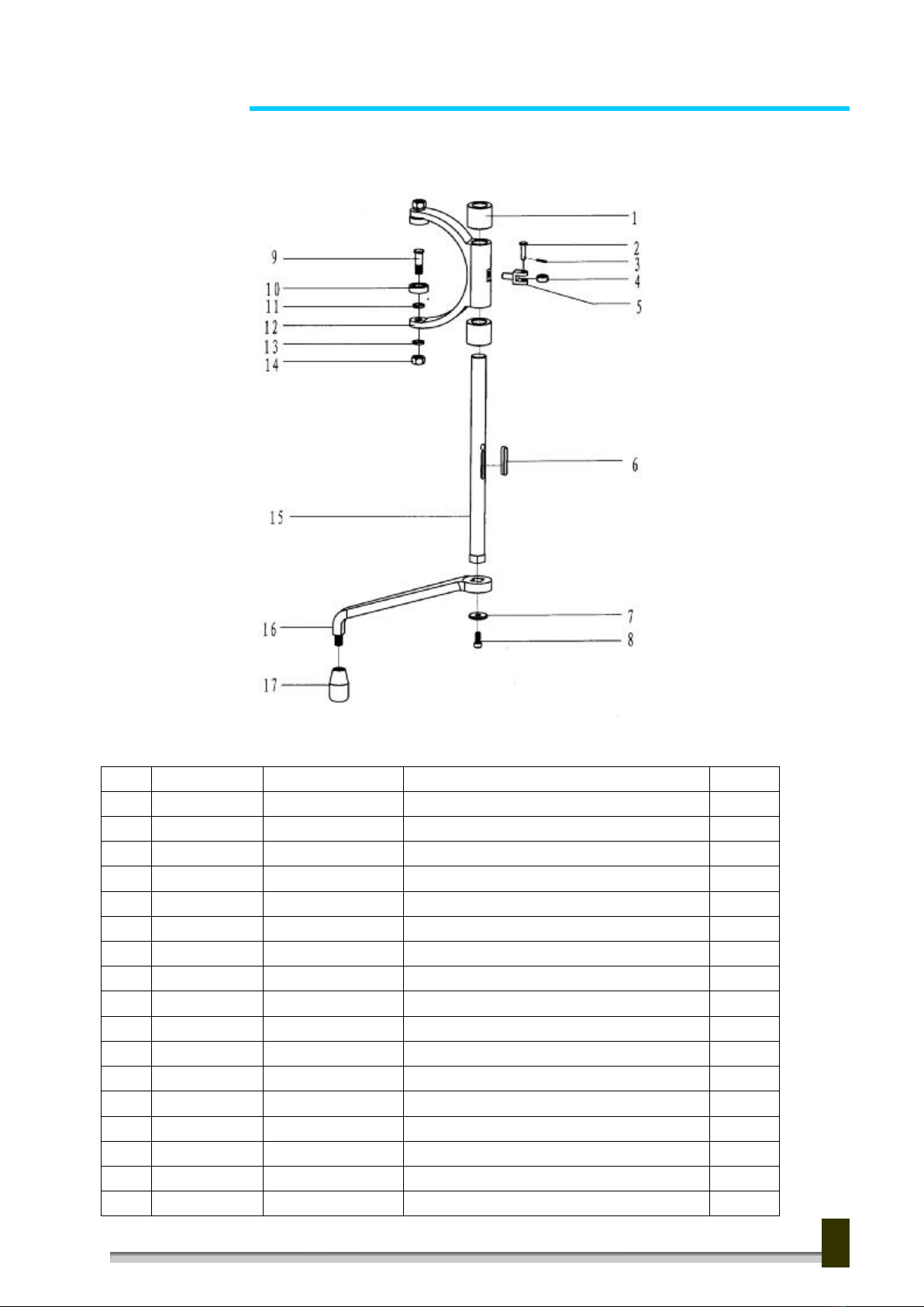
7. Attached figures and part list.
7.1 General assembly (Fig1. Table1)
Fig1. General assembly
Table1. Detailed table for General assembly
Item
Purchase No.
Part No.
Part name and Description
QTY
1
ZQ25-1
ZQ25.1
Master tong
1
2
ZQ25-3
ZQ25.3
Front guide pole assembly
2
3
ZQ25-2
ZQ25.2
Backup tong
1
4
ZQ25-4
ZQ25.4
Back guide pole assembly
1
5
ZQ25-5
XYQ12.YD-01.1
Hydraulic bucket
1
5

M o d e l Z Q 1 2 7 / 2 5 Y D r i l l P i p e P o w er T o n g
7.2 Master tong (Fig2. Table2)
Fig2. Master tong
Table2. Detailed table for Master tong
Item
Purchase No.
Part No.
Part name and Description
QTY
1
Shell assembly and parts
1
2
tong head assembly and brake
mechanism
1
3
ZQ25-30
Hydraulic motor J6K-625
1
4
Hand control valve and lift valve
1
5
Drive gear assembly and parts
1
6
ZQ25-21
ZQ25.1.6
Shift mechanism assembly
1
6

M o d e l Z Q 1 2 7 / 2 5 Y D r i l l P i p e P o w er T o n g
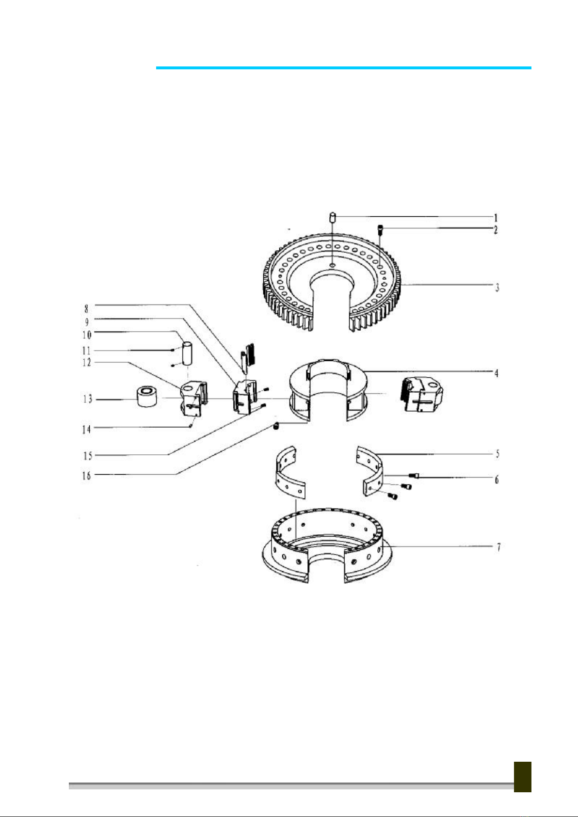
7.2.1 Shell assembly and parts (Fig3. Table3)
Fig3. Shell assembly and parts
7

M o d e l Z Q 1 2 7 / 2 5 Y D r i l l P i p e P o w er T o n g
Table3. Detailed table for Shell assembly and parts
Item
Purchase No.
Part No.
Part name and Description
QTY
1
ZQ25-47
GB70
Hexagon socket head cap screw M10×25
29
2
ZQ25-111
GB93
Washer 10
23
3
ZQ25-126
ZQ25.1.9-1
Safety door shaft
1
4
ZQ25-127
GB91
Cotter pin 5×35
1
5
ZQ25-53
Tension spring(Φ17×95)
1
6
ZQ25-125
ZQ25.1.9.1
Main body of safety door
1
7
ZQ25-121
ZQ25.1.8-6
Pin shaft
1
8
ZQ25-116
ZQ25.1.8-1
Tong head cover
1
9
ZQ25-12
ZQ25.1-2
Tong body
1
10
ZQ25-8
XYQ3C.Z.3
Fore handle(RH)
1
11
ZQ25-6
ZQ25.1-1
Fore support seat
2
12
ZQ25-7
GB70
Hexagon socket head cap screw M12×25
4
13
ZQ25-202
GB93
Washer 12
4
14
ZQ25-10
GB5781
Hex head bolt M10×20
6
15
ZQ25-177
GB65-85
Slotted cylinder head screw M6×10
12
16
ZQ25-203
ZQ25.1-14A
Name plate
1
17
ZQ25-48
ZQ25.1.7
Hanging rod
1
18
ZQ25-51
GB70
Hexagon socket head cap screw M12×100
2
19
ZQ25-204
ZQ25.1.7-1A
Hanging caput
2
20
ZQ25-50
GB91
Cotter pin 4×30
2
21
ZQ25-49
ZQ25.1-16
Hanging pin shaft
2
22
ZQ25-29
GB1152
Oil cup M10×1
2
23
ZQ25-46
ZQ25.1-13A
hanging seat
2
24
ZQ25-9
XYQ3C.Z.4
Fore handle(LH)
1
25
ZQ25-55
XYQ3C.Z-37
Back handle
2
26
ZQ25-26
XYQ12.Z-62
Tail guy pin
1
27
ZQ25-27
GB91
Cotter pin 5×35
1
28
ZQ25-24
ZQ25.1-4
Back guide rod seat
1
29
ZQ25-25
GB1096
Parallel key 12×40
2
30
ZQ25-23
XYQ3C.Z-21
spring
1
31
ZQ25-22
XYQ12.Z.1-21
Locating block
1
32
ZQ25-100
ZQ25.1.5-8
Bearing cover
1
33
ZQ25-20
GB70
Hexagon socket head cap screw M8×25
6
8
M o d e l Z Q 1 2 7 / 2 5 Y D r i l l P i p e P o w er T o n g
7.2.2 Tong head assembly(Fig4. Table4)
Fig4. tong head assembly
9

M o d e l Z Q 1 2 7 / 2 5 Y D r i l l P i p e P o w er T o n g
Table4. Detailed table for tong head assembly
Item
Purchase No.
Part No.
Part name and Description
QTY
1
ZQ25-69
ZQ25.1.1-9
Retainer pin
1
2
ZQ25-70
GB70
Hexagon socket head cap screw M12×30
30
3
ZQ25-68
ZQ25.1.1-8
Open gear
1
4
ZQ25-58
ZQ25.1.1-3
Jaw set bracket
1
5
ZQ25-57
ZQ25.1.1-2
Ramp
4
6
ZQ25-7
GB70
Hexagon socket head cap screw M12×25
12
7
ZQ25-56
ZQ25.1.1-1
Main body
1
8
ZQ25-65
XYQ12.Z-01.12(2-3)
Die (2-3)
Each
for 4
9
ZQ25-64
ZQ25.1.1-7(1-5)
Die seat(1-5)
Each
for 2
10
ZQ25-62
ZQ25.1.1-6 Roller shaft
2
11
ZQ25-63
GB71 Slotted cone end fastening screw M8×10
4
12
ZQ25-59
ZQ25.1.1-4
Jaw set
2
13
ZQ25-61
ZQ25.1.1-5
Roller 2
14
ZQ25-60
GB119
Cylindrical pin 6×18
4
15
ZQ25-66
XYQ12.Z-01.11
Screw retainer pin
20
16
ZQ25-67
XYQ12.B-10
Set screw
2
10

M o d e l Z Q 1 2 7 / 2 5 Y D r i l l P i p e P o w er T o n g
7.2.3 Tong head brake mechanism(Fig5. Table5)
Fig5. tong head brake mechanism
11

M o d e l Z Q 1 2 7 / 2 5 Y D r i l l P i p e P o w er T o n g
Table5. Detailed table for tong head brake mechanism
Item
Purchase No.
Part No.
Part name and Description
QTY
1
ZQ25-124
ZQ25.1.8-9
Brake blot
11
2
ZQ25-123
ZQ25.1.8-8
Brake spring
11
3
ZQ25-117
ZQ25.1.8-2
Friction disc
3
4
ZQ25-16
GB68
Slotted countersunk screw M5×10
63
5
ZQ25-109
ZQ25.1.6-2
shim
1
6
ZQ25-118
ZQ25.1.8-3
Brake steel plate
1
7
ZQ25-119
ZQ25.1.8-4
Knob shaft
1
8
ZQ25-14
XYQ12.Z-03
Centralizing roller
21
9
ZQ25-13
ZQ25.1-3
Centralizing roller shaft
21
10
ZQ25-116
ZQ25.1.8-1
Tong head cover
1
11
ZQ25-122
ZQ25.1.8-7
Brake disc
1
12
ZQ25-87
GB70
Hexagon socket head cap screw M6
×10
1
13
ZQ25-120
ZQ25.1.8-5
knob
1
14
ZQ25-47
GB70
Hexagon socket head cap screw M10
×25
4
15
ZQ25-55
XYQ3C.Z-37
Back handle
2
16
ZQ25-121
ZQ25.1.8-6
Pin shaft
1
12
M o d e l Z Q 1 2 7 / 2 5 Y D r i l l P i p e P o w er T o n g
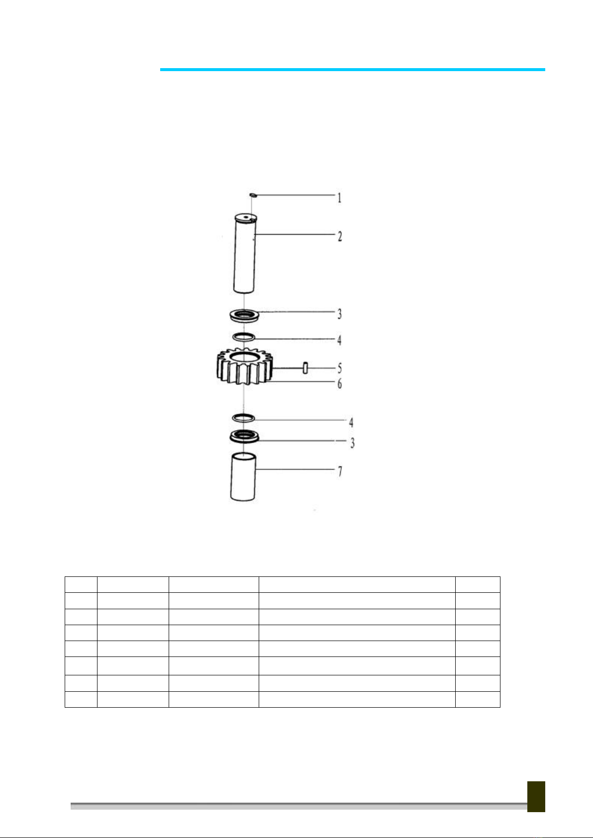
7.2.4 Idle shaft assembly (Fig6. Table6)
Fig6.Idle shaft assembly
Table6. Detailed table for Idle shaft assembly
Item
Purchase No.
Part No.
Part name and Description
QTY
1
ZQ25-86
XYQ3C.Z-5
Locating disc
2
2
ZQ25-80
ZQ25.1.3-4
Idler shaft
2
3
ZQ25-76
ZQ25.1.3-2
Seal ring(1)
4
4
ZQ25-77
GB1235-76
O ring 63×5.7
4
5
ZQ25-75
ZQ25.1.3-1
idler(1)
2
6
ZQ25-78
Roller Φ10×30
40
7
ZQ25-79
ZQ25.1.3-3
Shaft sleeve(1)
2
13
M o d e l Z Q 1 2 7 / 2 5 Y D r i l l P i p e P o w er T o n g
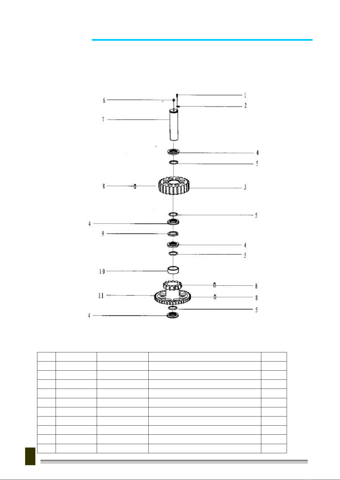
7.2.5 Duplex gear assembly (Fig7. Table7)
Fig7. Duplex gear assembly
Table7. Detailed table for Duplex gear assembly
Item
Purchase No.
Part No.
Part name and Description
QTY
1
ZQ25-87
GB70
Hexagon socket head cap screw M6×10
1
2
ZQ25-86
XYQ3C.Z-5
Locating disc
1
3
ZQ25-84
ZQ25.1.4-4
Idler (2)
1
4
ZQ25-76
ZQ25.1.3-2
Seal ring(1)
4
5
ZQ25-77
GB1235-76
O ring 63×5.7
4
6
ZQ25-29
GB1152
Oil cup M10×1
1
7
ZQ25-85
ZQ25.1.4-5
Duplex shaft
1
8
ZQ25-78
Roller Φ10×30
60
9
ZQ25-83
ZQ25.1.4-3
shim
1
10
ZQ25-82
ZQ25.1.4-2
Shaft sleeve(2)
1
14
M o d e l Z Q 1 2 7 / 2 5 Y D r i l l P i p e P o w er T o n g
11
ZQ25-81
ZQ25.1.4-1
Duplex gear(1)
1
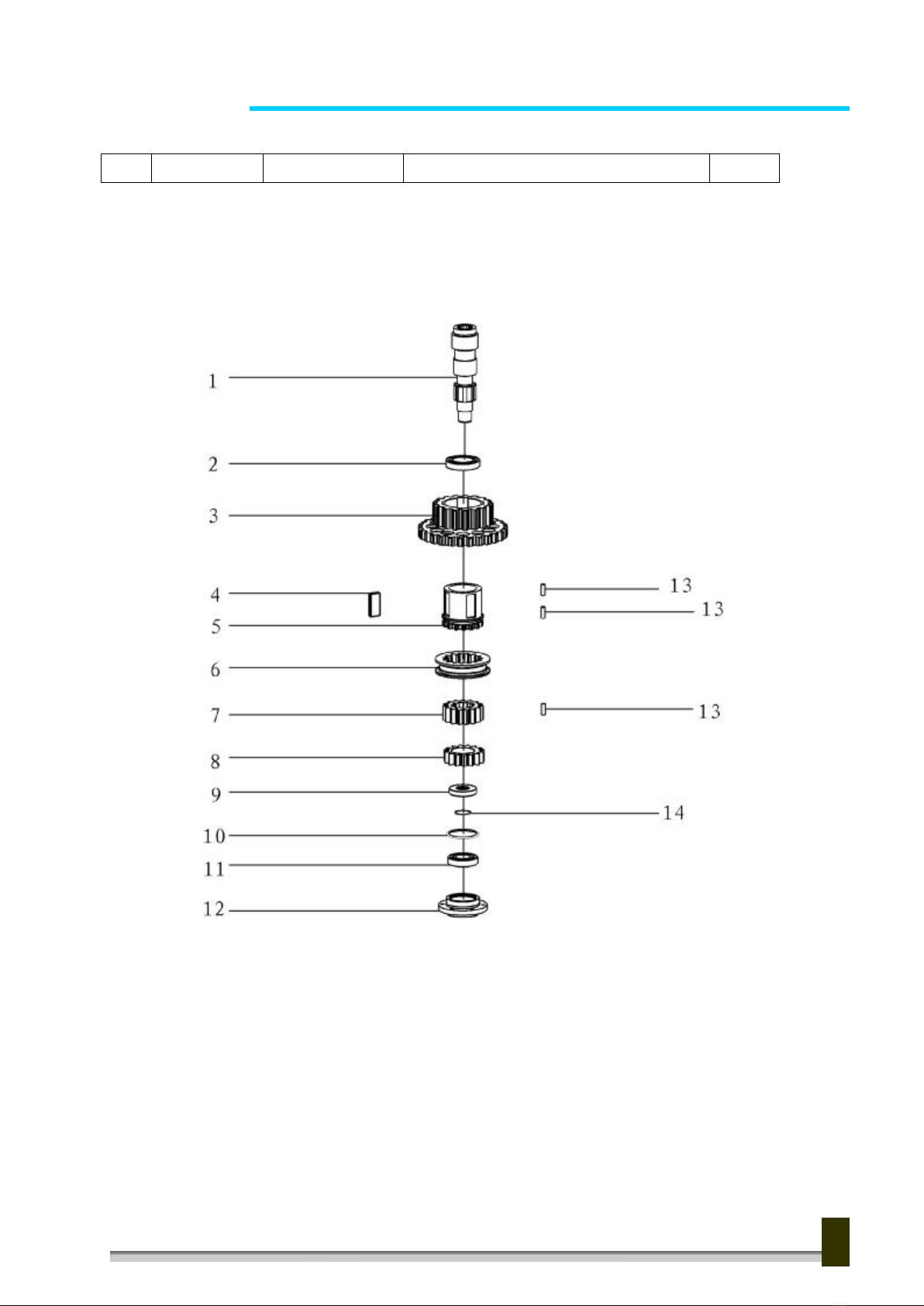
7.2.6 Power input shaft assembly (Fig8. Table8)
Fig8. Power input shaft assembly
15

M o d e l Z Q 1 2 7 / 2 5 Y D r i l l P i p e P o w er T o n g
Table8. Detailed table for Power input shaft assembly
Item
Purchase No.
Part No.
Part name and Description
QTY
1
ZQ25-88
ZQ25.1.5-1
Power input shaft
1
2
ZQ25-89
GB276
Deep groove ball bearing 112
1
3
ZQ25-92
ZQ25.1.5-3
Duplex gear(2)
1
4
ZQ25-91
GB1567
Thin flat key 28×10×63
4
5
ZQ25-90
ZQ25.1.5-2
Clutch gear
1
6
ZQ25-94
ZQ25.1.5-5
Inner gear sleeve
1
7
ZQ25-93
ZQ25.1.5-4
Inner spline gear
1
8
ZQ25-95
ZQ25.1.5-6
Shifting gear
1
9
ZQ25-96
ZQ25.1.5-7
Seal ring(2)
1
10
ZQ25-99
GB1235
O ring 80×3.1
1
11
ZQ25-98
GB276
Deep groove ball bearing 207
1
12
ZQ25-100
ZQ25.1.5-8
Bearing cover
1
13
ZQ25-78
Roller Φ10×30
68
14
ZQ25-97
GB1235
O ring 40×3.1
1
16
M o d e l Z Q 1 2 7 / 2 5 Y D r i l l P i p e P o w er T o n g
7.2.7 Shifting mechanism assembly (Fig9. Table9)
Fig9. Shifting mechanism assembly
Table9. Detailed table for Shifting mechanism assembly
Item
Purchase No.
Part No.
Part name and Description
QTY
1
ZQ25-101
XYQ12.Z-19.01
Shaft sleeve
2
2
ZQ25-104
XYQ3C.Z.6-4
Roller shaft
1
3
ZQ25-105
GB91
Cotter pin 2×10
1
4
ZQ25-103
XYQ3C.Z.6-3
roller
1
5
ZQ25-106
XYQ3C.Z.6-5
Roller support seat
1
6
ZQ25-107
GB1096
Flat key 6×6×40
1
7
ZQ25-109
ZQ25.1.6-2
shim
1
8
ZQ25-87
GB70
Hexagon socket head cap screw M6×10
1
9
ZQ25-112
XYQ12.Z-19.04
Bolt shaft
2
10
ZQ25-114
GB276
Deep groove ball bearing 100
2
11
ZQ25-113
GB848
Washer 10
2
12
ZQ25-102
XYQ12.Z-19.02
fork
1
13
ZQ25-111
GB93
Washer 10
2
14
ZQ25-110
GB6170
Nut M10
2
15
ZQ25-108
ZQ25.1.6-1
Fork shaft
1
16
ZQ25-115
ZQ25.1.6.1
Operating handle assembly
1
17
ZQ25-205
XYQ3C.Z.5-10
Handle
1
17
Table of contents
Popular Drill manuals by other brands


Makita
Makita DTS131 instruction manual

Hilti
Hilti TE 500-A36 Original operating instructions

Hitachi
Hitachi DS 10DFL2 Handling instructions

Ingersoll-Rand
Ingersoll-Rand 6L Series Product information

Cembre
Cembre SD-15PR-ECO Operation and maintenance manual

Harbor Freight Tools
Harbor Freight Tools Warrior 57383 Owner's manual & safety instructions


