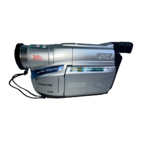
CHINON C8-1003 User manual

GHINT?N
- Fd,flF,J# ,- '"' txv&' -i t,. t
' Pocket 8 '
C8-1003 lnstruction$
t'
I r"
.l ,t
t
1,
4
I
q
Lioht Level . .. . 25
Aisemble Recording .. ... 26
Re-recordinq....... -.. ?7
insertRecoidinq..... ... . 29
Precautions ....... '. ...30
' Specifications ....- BackCcrver
fl*.
Cbarge Co,rphd Devi$
14
15
16
17
19
20

GHINFN
f€p _];,; J
- P*57F:ii ' '' t'
' Pocket
C8-1003 lnstructions
t,, I
1,
I
I
Lioht Level . .. '.. 25
Assemble Recording -'.--' 26
Re-recording.....:. ry
lnsertRecoidinq..... .. . 29
Precautions ......30
- Specificalions ..... BackCtrver
14
15
19
20 =#.
Charge C{ilJPbd Devie

ACGESSORIES
o CHINoN PocKEr t tlSl?}l*,iona'y avaitable.
The tollowing accessorlel
System C8-1003
Video AC.Adapter
c8-Ac33
lll"fi ii::tr;l.lu'mlf:laxlu""lru;':ll"
pn:$tl*tr::",:il",3ril::1'f .Tri':=*"
Date of Purchase. - , -
Dealer Purchased From
Dealer Address
+l _l
I
ffi3i-ffT*6t".'o"... -------
AEffiA
il- *-a** BEDU.E THE RlsK oF ELEcrBrc
"t"-o"*. oo "ot BEMovE covEE-(oR BA.K)
-""o'u!i*-"a"u,cao"LE PARTS lNSroE
REFER SEFVICING.TO OUALIFIED
SERVICE PERSONNEL
Ilr"lnTf
;'i',.'n:ffi ,'"i!Uli!fi i#i13;
A
/I\
/a\ ir":'dj:fi$iIi+i*:i1ilfrffi}jftguu
;*:{H :H,"5'*;:i;' ;n';:f; "ji li, J"" ili*' ""'
Serial No. ,-.
in oroet to avoid anY Problems
Battery Pack C8-833
Car Battery C;rd C8-CC33
(0 P. 14)

o Accessories packed with vour POCKET 8.
POCKETS C8-C60 Video AC Adapter
c8-AC33
Qp t,
14, 15, 16, 27, 28)
Battery Pack C8-833
m
\rfl (0 P.9, 14, 15)
(ilP 8)
AV Connector C8-AV33
@ P. 16,27 , 28)
arphone C8-E33
(0 P. 12)
VHF Connecting Cable
VSQSO2l 7
(0 P. 16) (0 P. 16)
Audio/Video Cable VJPSO2.I 6
o P. 16, 27 , 28\
CAUTION:
TO PREVENT FIRE OR SHOCK HAZARD AND ANNOYING INTERFERENCE, USE THE
RECOMMENDED ACCESSORIES ONLY.
Your POCKETS is designed to record and play back in SP mode only. The POCKET B will not perform
normal playback for programs pre-recorded in LP mode'
Only use 8 mm video cassettes bearing the E mark.
WARNING:
TO PREVENT FIRE OR SHOCK HAZARD, DO NOT EXPOSE THIS EQUIPMENT TO RAIN OR
MOISTURE.
WARNING:
ONE FEDERAL COURT HAS HELD THAT RECORDING COPYRIGHTED T.V. PROGRAMS.IS
INFRINGEMENT. SUCH PROGRAMS SHOULD NOT BE RECORDED.
a'

INNPORTANT SAFEGUARDS
1. Read lnstructions - All the safety and operatlng
instructions should be read belore the unit is
ooerated.
i!. Retain Instructions - The sa{eiy and operating
instiuctions should be retained for {ulure reterence
3. Heed Warnings - All warnings on the unit and in
the operating instructions should be adhered to'
4. Follow Instructions - All operating and maintenace
instructions should be Jollowed
5. Cleaning - Unplug this video unit from the wall
outler be{ore cleaning. Do not use liquid or aerosol
cleaners. Use a dry cloth for cleaning
6. Attachments -,Do not use attachments not
recommended by the video product manufacturer as
they may be hazardous.
7. Water and Moisture - Do not use this video unit
near waler - for example near a bath tub wash
bowl, kitchen sink. or laundry tub. in a wet basement'
or near a swimming pool, and the like'
8. Accessories - Do not place this video unit on an
unstable cad, stand, tripod, bracket, or table The
video unit may fall, causing serious injury to a child
or adult, and serious damage to the unit Use only
with a carl, stand, tripod, bracket, or table
recommended by the manufacturer, or sold with the
video unit. Any mounting o{ the unit should lollow
the manufacturer's instructions and should use a
mounting accessory recommended by the
manufacturer.
9. Ventilation - Slots and openings in the cabinet are
provided for ventilation and to ensure reliable
operation o'f the video unlt and to protect it lrom
overheating. These openings must not be blocked
or covered. Never place the video unit on a bed'
sofa, rug, or other similar sudace, or near or over a
radiator or heat register. This video unit should not
be placed in a built-in installation such as a bookcase
or rack unless proper ventilation is provided or the
manufacturer's instructions have been adhered to
10. Power Sources - This video unit should be
operated only from the type of power source
indicated on the marking label. ll you are not sure
ol the type of power supply to your home' consult
your appliance dealer or local power company For
video unils intended to be operated from battery
oower, or other sources, re{er to the operation
instructions.
11. Grounding or Polarization - This video unit may
be equipped with either a polarized 2-wire AC line
plug (a plug having one blade wider than the other)
or a 3-wire grounding type plug. a plug having a
third (grounding) Pin.
The 2-wire polarized plug will fit into the power
outlet only one way This is a safety Jeature lJ you
are unable to insert the plug fully into the outlet' try
reversing the plug. lt the plug still lails to til, contact
your electrician to replace your obsolete outlet Do
not defeat the safety purpose of the polarized plug'
The 3-wire grounding-type plug will fit into a
grounding-type power outlet This is a salety
feature. l{ you are unable to insert the plug into the
outlet, contact your electrician to replace your
obsolete outlet. Do not defeat the salety purpose
of the grounding{YPe Plug.
12. Power-Cord Protection - Power-supply cords
should be routed so that they are not likely to be
walked on or pinched by items placed upon or
against them. Pay particular attention to cords of
plugs, convenience receptacles, and the point
where theY exlt from the unit
13. Outdoor Antenna Grounding - ll an outside
antenna or cable system is connected to the video
unit, be sure the antenna or cable system is
grounded so as to provide some protection against
voltage surges and built-up static charges Seclion
810 ;f the National Electrical code, ANSI/NFPA
No. 70 - 1984, provides information with respect
to proper grounding of the mast and supporting
structure, grounding o{ the lead-in wire to an
antenna discharge unit, size of grounding
conductors, location of antenna-discharge unit'
connection to grounding electrodes and
reouirements for the grounding electrode
See Figure on next Page
3

T
aoNDlNG JUMPER (d) l\ o"t'o*or o"trlNo GRouNolNG
II \ ELECTRODE DBIVEN 8 FEET (2'4 M)
U INTO THE EARTH IF BEOUIRED BY
LMAL COOES. SEE NEC SECTION
810-21 ().
16. Overloading - Do not overload wall outlets and
extension cords as this can resull in a risk of fire
or electric shock.
17. Objects and Liquids - Never push oblects of any
kind into this video unit through openings as they
may touch dangerous voltage points or short-out
part that could result in a fire or electric shock
Never spill liquid of any kind onto the video unit.
18. Servicing - Do not attempt to service this video
unit yourself as opening or removing covers may
expose you to dangerous voltage or other hazards.
Refer all servicing to qualified service personnel.
19. Damage Requiring Service - Unplug this video
unit from the wall outlet and refer servicing to
qualified service personnel under the following
conditions:
a. When the power-supply cord or plug is
damaged.
b. lf any liquid has been spilled onto, or objects
have fallen into the video unit.
c. l{ the video unit has been exposed lo rain or
water.
d. lf the video unit does nol operate normally by
following the operating instructions. Adjust only
those controls that are covered by the operating
instructions as an improper adjustment of other
controls may result in damage and will often
require exlensive work by a qualified technician
to restore the video unit to its normal operation.
e. lf the video unit has been dropped or the cabinet
has been damaged.
f. When the video unit exhlbits a distinct change
in performance - this indicates a need for
service.
20. Beplacement Parts - When replacement parts are
required. be sure the service technician has used
replacement parts specified by the manutacturer or
have the same characteristics as the original part
Unauthorized substitutions may result in fire,
electric shock or other hazards.
21. Salety Check - Upon completion of any service or
repairs to this video unit, ask the service technician
to perform safety checks to determine that the
video unit is in sale operating order.
GROUND CLAMP
SEBVICE ENTFANCE STANOOFF
lNsuuToRS (b)
LEAO rN WIAE (b)
ANTENNA
DISCHARGE
UNIT (c)
POWEF SEBVICE GBOUNDING
ELECTRODE SYSTEM
{e.9. inlerior metal water pipe)
a. Use No. 10 AWG
(5.3mm'?) copper. No. I
AWG (8.4 mm'?) aluminum,
No. 17 AWG (1.0mm'?)
coppetrclad steel or
bronze wlre, or larger, as
ground wrre.
b. Secure antenna ead-in
and ground wires to house
with stand-off insulators
spaced from 4 teel (1.22
m)to 6 teet (1.83 m) apad
TO EXTEBNAL ANTENNA
TERMINALS OF PRODUCT
WIBE (a, b)
c. lvlount antenna discharge
unit as close as possible
to where lead-in enters
house.
d. Use lumper wire not
smaller than No. 6 AWG
(1 3.3 mm'z) copper, or the
equivalent, when a
separate antenna-
grounding e ectrode ls
used. See NEC Secton
810-21 (j).
1 4. Lightning - For added protection of this video unit
receiver during a lightning storm, or when it is left
unattended and unused for long periods of time,
unplug it from the wall
outlet and disconnect the
antenna or cable system,
This will prevent damage
to the video unit due to
lightning and
surges.
15. Power LineS - An outside antenna system should
not be located in the vicinity ol overhead power lines
or other electric ltght or power circuits, or where it
can fall into such power lines {$ circuits. When
installing an outside antenna system. extreme care
should be taken to keep from touching such power
lines or circuits as contact with them might be fatal.
i'

7oescntP{fou or cournous
dfiil'"
1. Accessory s!oe- ^^,
I i'?ii."'#i,,li llt*, ;i' !i:ffiqeXt,?l*''
l'ffi[{i: ar[:s;#^f,::fai!'i"r"" 27 28)
I 'l$if,-i]3i,"i'"r#tll',1''?"', 1 ffng"*#'*=i-'*
tfft*ffi*F*il'{ffiffitu'
li. Bi$l?hfit4j*I"t{o P e' 14) o''
l3: i6it;;'inJicator o P' e)
irm ***rx Utri f#: r'J ;;'
$::yfr|.T::J'io'i ,r, ,i ",8, 1s' 28' 2e' 30)
lt*"rt *"r."'"g indicator (0 P 15)
ffir "*"", t" ''tt''

e
1. Diopter adiust lever (il P. 11)
2. Electronic vievulinder (il P' 9)
3. Eyelet tab for shoulder strap (0 P. 8)
4. Start/Stop button (0 P. 12, 30)
5. EAR (earphone) iack () P. 12)
6. MIC (microphone) iack (| P. 23)
7. Power zoom buttons (il P; 11)
8. Grip (il P. 11)
9. Grip strap (0 P. 11)
10. Tripod mount screw hole (f P. 8)
11. Tripod guide hole (S P. 8)
Bottom view
@BRIGHTNESS CONTROL/FOCUS
These controls adiust the brightness and
focus of the viewfinder Picture.
NOTE: These controls have been set at
the factory. lt is not necessary to adjust
these controls under normal
circumstances. But, should it become
necessary it is recommended that you use
a olastic screwdriver and make the
adjustment with caution so as not to
damage the miniature controls.

RIPTION OF CONTROLS CONTINUED
VIDEO AC ADAPTER C8-AC33
1. Battery compartment-cover ((; P' 15)
a: BgwEn'#'i".?li! (8i;l i"r
a. fvruCn selector (i P. 16)
;: vci/cHARGE sel6ctor (t q' 14' 1s)
e. cinn-cilndicator (| P' 1s)
i. litutti-Pin Plug () P. 14).
b. lux (auxitiary; terminal
5. ij"tteli co.Pd+t:ll (f l'^Jsl
i?: lKfJ^f'X,l iilili$'l*'ft ,'(i',' u)
ii. luoto lN teiminal 1f e' z9)
i5. Vtbeo lN terminal (il P' 28) --.
ii. nUoto ilui terminit tt' e' 19' 3t
ii. ilr-oeo out terminat (0 P' 16' 27)
16. AC Plug ().P. 14'.1s)
i7. nF 6na-nriel selector (i P' 16)
Bottom view
CAUTION: Operation at a voltage setting
ii tloiizotz+oV AC mav require the use o{ a .
i,rt"r"nt AC plug. Please contact either a local
oi rct"iqn electiical parts distributor for
irriitui". in selecting an alternate Ac plug'
W" t""o.tund using the accessory Power
pirg AJ"ptot (v.lssobzo) in an area which
has special AC outlets.
CAUT|oN:ToPREVENIELECTR|CSHocKDo.NoTUSETH|S(PoLARIZ_ED)PLUGWITHAN
EXrENsroN cono, n-"e??'{cf_"o[g1]{iiouiiriur'rr-ess iHr BLADES cAN BE FULLY
i-ris^iRE!.io-il,ivFII#KBt E5?on%T.tELEcrRreuES NE pAs utLrsER cErrE FrcHF-
ilIiHIS?l'f"?3i,RX'ruiaruoiieiji, u1e-pnrs'E'EE?"ouEA^ri-9y ^uryE AUrRE soRrrE
DE couRANr. SAUF s' E5:.AGf;;unii'Jr eiiE ir'rsEnirs e roruo SANS EN LArssER
lucurle PARTIE A DEcouvERT'

FOR EASY HANDLING
How to attach the shoulder strap
How to mount on the tripod
Use a tripod designed specifically for video cameras
Mounting screw
Screw the strap mounting screw on the other end
of the strap into the tripod mount screw hole on
the bottom of the C8-C60.
Guide one end of the strap through the CB-C60's
eyelel tab, enteriqg the eyelet from the side
opposite the viewfinder. Then pass the strap
through the sirap's loop and the adjustment
buckle.
Adjust the strap to a comfodable length.

BASIC OPERATION
(1) Attach the Battery Pack C8-833
(provided).
Rest the bottom end of the Battery Pack on the.
ii'ao-" J6nd the bottom edge of thir CB-C60, and
swinq the-Battery Pack into place as shown'
making sure it locks.
To remove the Battery Pack' press down.on the
BATTERY EJECT button while pulllng Ine
Battery Pack awaY from the CB-C60'
Zoom lever
Release the zoom lever
from Macro mode
Switch on the Power'
BATTERY EJECT button
Power source
. fo oo*er the C8-C60, a Video AC Adapter and
ClrEattery Cord are available in addition to ihe
Battery Pack. (0 P. 14)
. lf a power unit is disconnected from the C8-C60
rnir6-iiii ieiorcing or playing back a tape' the
taoe remains wound around the video neao orum'
l-nO tnis can lead to tape damage Be sure to
disconnect the power unit only after turnlng tne
POWER switch off
When using a Battery Pack:
r Make sure it is fullY chargeo.
o Before removing tfte Battery Pack, allow a lew
!J"6nOs-att"r' tJrning the POWER switch off'
Viewfinder Indicators
el.id"t ine image being recorded or played back'
tne toffowing inf6rmation is displayed in the
viewfinder.
1, Record/Battery warning indicator (green)
- Liqhts while rebording. and blinks wnen Ine
diii"iv pi.x's power-is getiing low. (0 P 15)
i Whitsbalance warning indicator (orange).
- ii;'hi; wnJn irre WHITE- BALANOE selector is
",it r t|.'" FULL AUTO position (0 P 24)
g Exposure indicator bar
" ln;Icat;a the amount of exposure by its
position. (0 P. 25)
(2) Preset the camera controls as
VCR/CAMERA
to CAMERA
ITE BALANCE
selector to FULL AUTO

2.
(4) Load a video cassette.
1. Press the cassette EJECT button.
The cassette holder will oPen.
lnsert a video cassette.
The video cassetle window must be facing
ouI.
Confirm that the
accidental erasure
prevention switch is
set lor recording.
3. Close the cassette holder.
The POCKET I enters
the Record Pause
mode.
Using the accidental erasure prevention switch
lndicatorwindow Accidentalerasure
orevention switch
To avoid accidentally erasing important recordings,
slide the accidental erasure prevention switch so
that the indicator window shows red.
To record, set the switch to its former position'
Recording is possible.

BASTC OPERATTON (CONTINUED)
tu%
(5) Position the C8-C60 for shooting.
Adjust the grip strap
to a comfortably tirm
tightness.
(6)
Lightly place your two
forefingers on the
power zoom buttons.
on the Start/Stoo button.
Check the image through the
viewfinder and choose a desired
composition using the zoom lever
or power zoom buttons.
Power zoom buttons
Press W (wide) to jncrease the angle of view
Press T (telephoto) for zoom-up shots.
The lens cap hook
To keep the lens cap out of the way while
recording, clip it onto the grip strap using the lens
cao nooK.
Diopter adiustment
Should the image in the viewfinder be unclear,
adiust the diopter as necessary. This is particularly
useful for people requiring eyeglasses.
Diopter adjustment lever
Look through the viewfinder, and slide the diopter
adjustment lever until the exposure indicator bar is
clearlv visible.
o The eyecup can be swung
open.
o Open for better viewing
of the image in the
viewiinder from a
distance.
Note: When the viewfinder eyecup
is exposed to direct sunlight it
works as a magnifying glass. Do
not leave the eyecup open when
the concentrated sunlight is
focused on the battery or the outer
oarts.

(7) Press the Start/Stop button.
Recording begins and the recording
indicator in the viewfinder illuminates.
Pressing this button again stops recording
temporarily (Record Pause mode) with the
recording indicator going off.
o
Recording indicator---O
Note:
When continuing recording again after turning
the power off once, a few frames of the last
recorded scene will be erased. (See "Assemble
Recording", 0 P. 26)
Recording review
You can check in the viewfinder if the scenes
have been recorded as intended by simply
pressing the REC/REV button.
Press the REC/REV button in the Record Pause
mode, keeping the VCR/CAMERA selector in the
CAMERA oosition.
The last few seconds of the just-recorded section
are played back, then the Record Pause mode
is automatically resumed.
o When the Pause mode cohtinues for more than
5 minutes, the Standby mode will be
automatically entered. Pressing the STANDBY
button again returns the C8-C60 to the Record
Pause mode. (il P. 13)
r The C8-C60 enters Stop mode automatically
when the end of the tape is reached during
recording.
o The power automatically shuts off when battery
power becomes insufficient.
e Panel indications show the operating mode.
Recording
Record pause
Audio monitoring
Connect the provided earphone to the EAR jack to
monitor the audio during recording and to listen to
the recorded sound during playback.
l--)
ll^ll
\-2
l-===-l
ll'__:__il

t
(8)
1.
Press the cassette unlock latch to release
the cassette'
. H:::It:ffivideo cassette and close the
4. Turn off the power and put on the lens
cap.
coNTlNuED
After recording
Press thi cassette EJECT bufton' h-*naffi tt**ti"Sq***""1'ij"""*""
;tuf,"riifi "tJ t"u d"5"0 i ng recordinss'
:tH*". ?Jfi-,?3#il1il;ln" Picture wirr
|"rir"*," recording alwaYs^enter Pause mooe
: HT1iiffi ffi "& T'"""':l*:J t lilloJu"" o u' n g
StandbY mooe'
ro restart *9"1S1"1-pJ,:3LlIl?;13[1t'o o*to"
after Pressing th€ o t ntrY"
During Standby mode' the indicator panel blinks'
- lll-Rl i, ll
ll- Jl -
-..ffi1::-
POWER indicator goes out
13

POWER SUPPLIES
The following power supply units are available to power the C8-C60. Choose the unit from those shown
below that best meets Your neeos.
o Use a Battery Pack that is sufiiciently
charged.
o Before removing, allow a few seconds
after turning off the Power.
o Refer to page 9 for details on attaching
and detaching the BatterY Pack.
. See page 15 for recharging.
(3) Plug into an AC outlet.
@
Set to VCR.
1) Confirm that power is off
(5) Turn on power.
indicator lights while the Video AC
(a) Plug into the ADAPTER terminal.
o Use the optional Extension Cable C8-5C (5m/
16.4 ft. long) to extend the Video AC Adapter
caDle.
Adapter is being powered.
o This cord can be used only with a
negative-grounded car powered by 12
V DC. Never use with positive-grounded
or 24 V powered cars.
o Keep the engine running when using
this power unit.
. Power of the C8-C60 automatically
shuts off when voltage drops Allow 10
seconds before resupplying power to
the C8-C60.
Plug into the
ADAPTER terminal.
(1) Start the car engine
and plug into the socket.
. lf the power supply unit is disconnected during.
recording or playback, the tape remains wound
around the video head drum when it stops,
and can result in possible damage to the tape.
Be sure to didconnect the power supply unit
only after turning ofl the POWER switch of the
c8-c60.
o No other power supply unit can be used with
the C8-C60.

BATTERY CHARGING WITH AC ADAPTER
Battery warning indicatot
When ihe battery power is insufiicient
rel
\-------------ary
The BATT indicator blinks on the indicator Panel.
"-5-l
-.A,j Mp)
-2"111--5$1
When recording is taking place, the viewfinder's
record/battery warning indicator blinks'
The Battery Pack's power will be consumeo tn
a lew minutes.
Recharge the Battery Pack or exchange your
current battery for a charged one'
Recharging the BatterY Pack
use tfrJvideo AC AdaPter CB-AC33
(4) Set the Battery Pack
(3) Open the battery
compartment cover.
Confirm that the
power is off.
Switch the Power on.
Do not use any other charging equipment
(2) Set to CHARGE.
(The Battery Pack
cannot be rechargeo
when this swtich is
set to VCR.)
(5)
@
Plug into an AC
outlet.
CHARGE indicator
(Lights while chargrng
is taking Place and goes
out when charging is
f inished.)
This is a "discharged battery"
reminder.
You maY manuallY operate this
switch.
Notes:
. ine c8-co0 can record continuously for 1
hour with a fully charged Battery Pack undel
an average temperature oI 25'C (77"F)'
However, the total recording time will be
shorter if it is used intermittently or in lower
temoeratures. Turning off the power wnen nol
in use is recommended.
r Power is consumed during the Record Pause
mode and StandbY mode as well as the
Recording mode. Therefore, to avoid recordlng
interruptions, it is recommended you bring
extra Battery Packs that can allow for two or
three times more recording time beyond what
vou are Planning.
For a longer life of the Battery Pack:
o Avoid overcharging
o Store the battery in a cool, dry place'

CONNECTION DIAGRAM WITH A TELEVISION
When you want to watch the picture being recorded or played back on a TV screen, connect the C8-C60 to the power
unit and the TV set as follows.
When using a TV without audio/video input terminals
Connect the Video AC Adapter C8-AC33 (provided) as shown below
VHF Connecting Cable (provided)
VHF antenna UHF antenna TV set
To VHF antenna
terminal on TV
To the TV output terminal.
To ADAPTER terminal
To the ANTENNA
input terminal
0r)l
Plug into an AC outlet
When using a monitor TV with audio/video input ierminals
Connect the Audio/Video Cable (provided) between the AUDIO and VIDEO terminals of the AV Connector or power
supply unit and the AUDIO IN and VIDEO lN terminals of the TV set, as shown below.
To watch a TV broadcast, disconnect
the CB-C60 or set the C8-C60's POWER
switch to "off".
,o, & r ,o,
.'',K@)f.ll\-/
l-l \'q
300O-75O F-connector
Antenna Adapter
(provided)
TVA/CR selector
TV: For watching the TV program
VCR: For playback
o There are two types of antenna leads:
(A) 3000 Twin-Lead (flat) cabie uses a
300O-75O Antenna Adapter.
(provided).
(B) 75O Coaxial cable uses an F-
connector, which can be directly
connected to the antenna input
terminal.
RF channel selector
Select channel 3 or 4, whichever is nol
used in vour area. lf both are used,
select th-e least viewed. The unit will
override unwanted signals when in the
Playback mode.
CONV
ITTI
ilt l
tul
cH4 CH3
When using the Battery Pack: When using the Video AC Adapter: using the Car Battery Cord:
Set the switch
To ADAPTER to OUT To ADAPTER
To car's
AV Connector To ADAPTER
(provided)
o VIDEO
Plug into an lighter
socket
'q AC outlet
To AUDIO To VIDEO OUT
To VIDEO
To AUDIO
OUT
To VIDEO lN >
@
Set the.switch
To VIDEO
To AUDIO lN To AUDIO lN

PLAYBACK
I !" r:"9;o-"1,1"H ":.1:,:3 gffi jf:&3"(3'i: i E;
#;;-;i a TV bonnected to
Note: Tapes recorded in LP mode cannot be RlaVed bacTn YCS'C60'
back and viewed either on the viewlinder of the C8-C60 or on tne
O I s"-ls"n,n" vc R/GAM ERA selector to vcR'
(2) Turn the powER "*,*i-on,-press the """"",[!-lecT button and load a recorded video
- cassette.
(3) OPen the control Panel cover'
(4) Press PLAY button' lndicator Panel
EPlavback begins'
'p." ffi""",lJl ", d;i"s;,i se' gff l3'?o' !l ! |r' * n
@r@r@
.u.J&E64 r"tu't*
F Yp"P.p*
6) t** STOP button to stop playback' o Press the PLAY button again to resume
playbacr.
17

o Fast-Forward
FF PLAY REW
6<) -f-?--)-f-D-) (-
dbueJ ffi Lneuew
w__
"(j!J t-!J tllJ tJ
STOP PAUSE/ST]LLINSEFI
Press the FF button in the Stoo mode
t
I
. Rewind
t<,Tt < ,ikDr la, tmt
-l-l*- ll ll
rcJ F=--dFVl L#Brs ll ll
-@
il ..tl
@ arltEl O L:==-----J,
FADV STOP PAUSE/STLLL INSEFT
Press the REW button in the Stoo mode.
. When tape end is reached during playback or fast forward, the tape is automatically rewound to its
beginning and the Stop mode is entered.
Tape counter The tape counter indicator is displayed on the
indicator panel. lt changes as the tape advances,
and is useful for locating specific scenes later.
Pressing the counter RESET button resets the
tape counter to "0000".
Counter Memory (searching for a specific tape section)
The tape will automatically stop around the counier reading of "0000" when fast forwarding or rewinding
in the Counter Memory mode. This is convenient for locating the same scene for repeated viewing.
(Setting the counter memory)
1. Press the counter RESET button at the point 2. Press the counier MEMORY button.
you wish to return to during playback.
1
I
ll u rt t-r t-t t-t ll i'tEMoRY
ll ., e, ,_r ei ll nesrr I
ll ll rm n')
|\- \:/ \'#/
"M" will be displayed.
Pressing the counter MEMORY button once
again releases the Counter Memory mode, and
the "M" disappears.
"u"uJttl"t
rR rn
w, tgl
:
| | f-, t-t t-t t-t | |
ll "''''''ll
Tape counter resets to "0000".
Table of contents
Other CHINON Camcorder manuals

