Chinowing D03 User manual

www.chinowing.com
D03
RC Range Extender
User Manual

2
www.chinowing.com
Content
1. Disclaimer.................................................................................................................3
2. Product Notes...........................................................................................................3
3. Product Introduction................................................................................................4
4. Item List.................................................................................................................... 4
5. Product Operation Instruction................................................................................. 5
5.1. Connection Diagram of Ground End.............................................................5
5.2. Connection Diagram of Airborne end...........................................................6
5.3. D03 Indicators Instruction.............................................................................7
5.4. Diagram of Module Normal Connection...................................................... 8
5.5. Read and Modify the Parameters Setting of Radio Link...............................9
5.6. Note.............................................................................................................12
6. The RC Fail-Safe Setting..........................................................................................13
7. Firmware Upgrade..................................................................................................14
8. Common Questions................................................................................................16

3
www.chinowing.com
1. Disclaimer
Thank you for purchasing the D03 Dual Link Radio (hereinafter referred to as "D03"). Please read
this statement carefully before using it. By using it, you will be deemed to have accepted all the
content in this statement. Please install and use the product strictly in accordance with these
instructions. Shenzhen Chinowing Technology Co., Ltd will not bear any legal responsibility for
any results or losses caused by improper use, installation, final assembly, modification.
2. Product Notes
1) Power supply of D03 airborne unit and ground unit: DC7.4-12V (lithium battery 2s-3s), please
strictly follow this data to power the module.
2) Be sure to install the antennas before power on to avoid damage to the circuit.
3) Make sure the antenna is free of obstruction and bending, and keep it away from large metal
object to avoid blocking the communication.
4) Please do not disassemble or modify D03. If you encounter any unsolvable problems in the
process of installation or use, please contact us.
5) Maintain a suitable distance between each device to minimize electromagnetic interference
between the equipment.
6) Before use, please ensure that all the connection is tight and reliable, all components work
properly.
7) Before use, please check the surrounding environment to ensure that no other
840MHZ-930MHZ equipment interference, otherwise the D03 data transmission may be
seriously affected.
8) If you encounter any problems that cannot be solved during the installation or use of the
product, please contact us or refer to our website: www.chinowing.com

4
www.chinowing.com
3. Product Introduction
D03 dual-link radio can transmit remote control signal and data transmission signal
simultaneously. It is mainly used to solve the problem of short transmission distance and low
quality of remote control signal and data transmission signal. D03 operates in the 900MHZ
frequency band, max communication distance can reach 30KM.
4. Item List
Main Modules
Ground unit ×1
Airborne unit x 1

5
www.chinowing.com
Accessories
5. Product Operation Instruction
The D03 has two signal outputs, one S-BUS signal and one serial signal. If your remote control or
receiver does not support S-BUS, you need to buy PWM to S-BUS module. Please follow the
connection diagram below to connect each module.
5.1. Connection Diagram of Ground End
Power cable x2
Standard USB wire
Parameters setting
cable
Power for
module
(DC:7.4-12V)
Used for parameters
setting or serial port
connection for ground unit
Used for parameters
setting for airborne
unit

6
www.chinowing.com
5.2. Connection Diagram of Airborne End
After successful connection, pls refer to the below steps to check the connection status.
(Different flight controller, this procedure differs a little.)
1. Open the Device Manager of the PC, you can see that the ground end is correctly recognized,
the driver is correctly installed, no yellow exclamation mark.

7
www.chinowing.com
2. Open the ground station software, select the corresponding COM port and connect to the
flight control. The normal connection of the flight control means that the D03 module's data
transmission link has been connected. If the connection fails, please check the following points.
1) Whether the baud rate of the flight control and the D03 are the same.
2) Make sure the ground unit driver of D03 is installed successfully.
3) Use the parameters setting software of D03 to ensure that all the parameters of the
airborne unit and the ground unit are consistent.
4) Make sure that the RX of the flight control corresponds to the TX of D03 and the TX of
the flight control corresponds to the RX of D03.
3. Open the RC setting interface in GCS software and check if the data of the remote control is
normal. If the data of the remote control changes normally with the joystick, the remote control
link is connected. If the remote control connection fails, please check if the "-, +, signal" of S-BUS
is reversed.
5.3. D03 Indicators Instruction
① S-BUS data indicator L1
Flashing means there is data transmission of RC link, no flashing means no data transmission
of RC link

8
www.chinowing.com
②Configuration indicator L2
Always ON means in the configuration mode
③SET button
Used to enter radio configuration mode or set Fail-Safe protection output values or upgrade
firmware
④Data transmission indicator
When the RXD light is on, the receiver is receiving data, and when the TXD light is on, the
receiver is sending data.
⑤Signal Strength Indicator
Indicator S1 S2 S3 is signal strength indicator. S1&S2&S3 ON, it means strong singal; S2&S3
ON, it means moderate signal; S3 ON, it means weak signal.
5.4. Diagram of Module Normal Connection
After power-on the airborne end and ground terminal, the indicator status is like the below, it
means 2 modules have connected normally.
Airborne Unit
Ground Unit
Continuous ON
Continuous ON
Flashing
Continuous ON
Continuous ON
Continuous ON

9
www.chinowing.com
5.5. Read and Modify the Parameters Setting of Radio Link
The D03 parameters have been set at the factory. You should be able to use it directly.
In the following cases, you may need to modify the radio parameters.
1. The baud rate of flight control is not the same as the preset baud rate.
2. Communication blocked due to multiple D03 radios occupying the same communication
channel.
3. There is special requirements for communication bandwidth and communication power.
To modify the parameters, pls refer to the below steps.
The way to modify the parameters of the airborne end and ground end is basically the same,
only the connection cable to the computer is different.
1) Hold down the SET key and power on until the L2 light comes ON, then release the key
2) Follow the connection methods in Figure 1 and 2, connect the ground terminal and computer
or the airborne terminal and computer respectively. Note that the white line of the on-board
parameter configuration wire corresponds to the on-board TX, the black line corresponds to
GND, and the green line corresponds to RX.
Fig 1 Airborne end connection

10
www.chinowing.com
Fig 2 Ground terminal connection
2. Please confirm whether your data link is H840 or P900, and then select the corresponding
parameters setting software.
1) If you are using Version H840, use the corresponding parameters setting software, select the
corresponding port and click the connection to read the data link parameters, as shown in the
figure below(Note: H840 is currently, no production)

11
www.chinowing.com
If you want to change the data link parameters, just change the corresponding values in the
software, click on Write, and then OK, as shown below
2) If you are using P900 module, pls open the corresponding parameters setting software
To modify the baud rate of the serial port, select the corresponding port, then click
Connect, select the corresponding baud rate, and finally click Disconnect.
If you want to modify the data link ID (address) and output power.
①Open the parameters setting software,click

12
www.chinowing.com
②After filling out the address and output power, click first, and then click disconnect.
Do not change any other values during this process, or D03 may not be able to communicate).
3. After the modification, press the set key again or power on again to exit the configuration
mode.
5.6. Note
When modifying the parameters, please make sure that the parameters of the ground unit
and the airborne unit are same, otherwise the two modules cannot communicate.
Communication bandwidth and communication power directly affect communication

13
www.chinowing.com
quality and distance. Do not modify the values of these two parameters if you do not
understand their specific meanings.
After entering configuration mode and completing the parameter configuration, be sure to
exit configuration mode.
When you configure P900 version data link system, please strictly follow the picture to
configure the contents, do not modify other values, otherwise the radio may not
communicate normally.
6. The RC Fail-Safe Setting
If the user needs to set the use protection for the remote control, do the following
1)Write Fail-Safe Protection Data
When the airborne unit and ground unit are connected normally, and there is remote control
data transmission, short press the set button on the airborne unit (about 0.5S, the L1 and L2
indicators will light up at the same time for about 1S after releasing), then the current remote
control value can be stored in the airborne unit as fail-safe value, and will not be lost after power
failure. Please check whether the fail-safe data is written successfully by testing the flight control,
ground station or servo.
2)Trigger Fail-Safe Protection Value
When the airborne unit does not receive S-BUS data from the ground unit for consecutive 3S, the
airborne unit will keep outputting the previously written fail-safe protection value until it
receives S-BUS data from the ground unit.
3)Close Fail-Safe Protection Data
When the airborne unit and ground unit are connected normally, and there is data transmission
from the remote control, press and hold the set key (≥5S) on the airborne unit until the L1 and L2
indicators are on at the same time (about 1S), turn off the fail-safe data, and the fail-safe data
will not be lost after power failure. Please test if the fail-safe data is off by the flight control,
ground station or servo.
Note:
By default, there is no fail-safe protection value output from the data link system.
14
www.chinowing.com
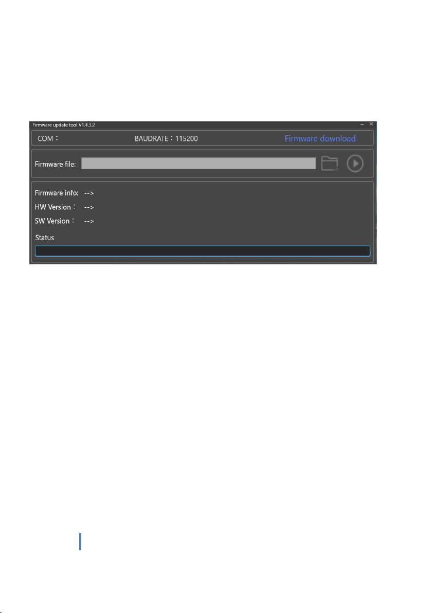
7. Firmware Upgrade
1)Open Bootloader Upgrading Software
r
2)Connect a USB cable or configuration cable to the USB port or TTL port, press and hold the set
key to power on, the L2 lamp is always on, and then press and hold the set key again until L1, L2
is always on at the same time, and the upgrade software shows the port number, it means in the
upgrade mode.

15
www.chinowing.com
3)Open the correct firmware you have downloaded. If correct, it will show that the firmware file
recognition is completed.

16
www.chinowing.com
4)Click on the Start button, until indicating that the download is completed, it means the
upgrade is successful.
8. Common Questions
1)Receiver S-BUS port has signal output, but the serial port is not connected, or the transmitted
signal is garbled.
Please check if the baud rate of the serial port of the airborne unit and the ground unit are the
same; and set the baud rate to the corresponding baud rate of the ground station software.
2)There is interference when two or more devices are turned on at the same time.

17
www.chinowing.com
Please check that the ID of each set must be different, and the channels must be set to different
values to avoid co-frequency interference.
Table of contents


