Chipsee CS19108R125P-C111 User manual

CS19108R125P-C111
User Manual
Release 1.0
www.chipsee.com

www.chipsee.com
2CS19108R125P-C111 User Manual (1.0)
Table of Contents
Table of Contents ............................................................................................................................................ 2
Chipsee Products Naming Rules................................................................................................................... 3
Hardware Features .......................................................................................................................................... 4
CS19108R125P-C111 ................................................................................................................................... 5
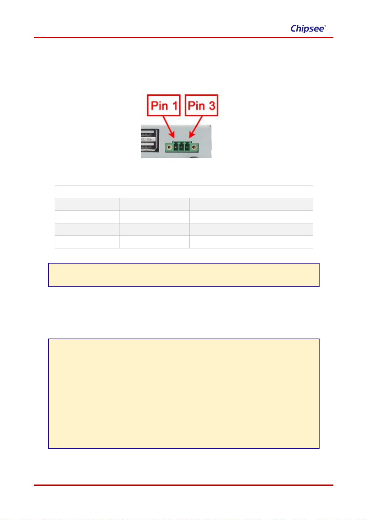
Power Input Connector .................................................................................................................................. 6
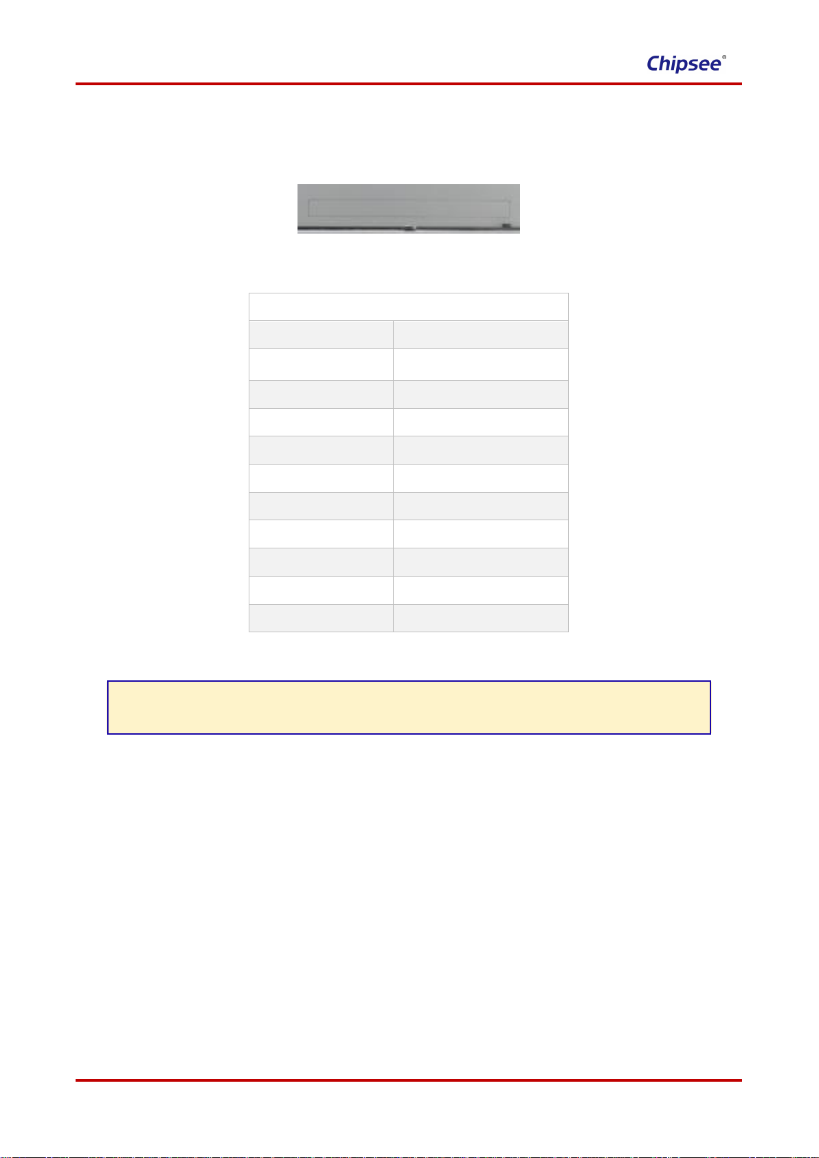
Capacitive Touch ........................................................................................................................................... 6
DB9 Connector............................................................................................................................................... 7
USB 2.0 Connector .................................................................................................................................. 7
USB 3.0 Connector........................................................................................................................................ 7
USB Type-C................................................................................................................................................... 7
LAN Connector............................................................................................................................................... 8
TF Card.......................................................................................................................................................... 8
SIM Card Holder ............................................................................................................................................ 8
Audio Connector ............................................................................................................................................ 9
WiFi+BT ......................................................................................................................................................... 9
HDMI Connector ............................................................................................................................................ 9
Power Button.................................................................................................................................................. 9
Expansion Connector................................................................................................................................... 10
Measurements and Mounting....................................................................................................................... 11
Measurements ............................................................................................................................................. 11
Mounting Method ......................................................................................................................................... 12
How to Get Support....................................................................................................................................... 13

www.chipsee.com
User Manual (1.0) CS19108R125P-C111 3
Chipsee Products Naming Rules
CS19108R125P-C111
CS
Chipsee Product Abbreviate
19
Horizontal Resolution
80 Means 800 Pixel
10 Means 1024 Pixel
12 Means 1280 Pixel
14 Means 1440 Pixel
19 Means 1920 Pixel
108
Vertical Resolution
480 Means 480 Pixel
600 Means 600 Pixel
768 Means 768 Pixel
800 Means 800 Pixel
900 Means 900 Pixel
102 Means 1024 Pixel
108Means 1080 Pixel
R(T/F)
Product based on Rockchip (TI/Freescale) CPU
125
LCD Dimension
050 Means 5.0 Inch
070 Means 7.0 Inch
080 Means 8.0 Inch
097 Means 9.7 Inch
101 Means 10.1 Inch
104 Means 10.4 Inch
120 Means 12.0 Inch
125 Means 12.5 Inch
150 Means 15.0 Inch
156 Means 15.6 Inch
170 Means 17.0 Inch
190 Means 19.0 Inch
215 Means 21.5 Inch
P
Means Embedded PC or Panel PC
EMeans Embedded PC without Case
P Means Panel PC with Case
C
Means Touch Type
R Means Resistive Touch
C Means Capacitive Touch
1
Means LCD Brightness
1 Means Common Brightness
2 Means High Brightness
1
PCB Version
Baseboard PCB Version Number
1
PCB Version
SOM Module PCB Version Number

www.chipsee.com
4CS19108R125P-C111 User Manual (1.0)
Hardware Features
Key Features:
CPU
Rokchip RK3399, Dual-core Cortex-A72(1.8GHz),
Quad-core Cortex-A53(1.4GHz)
RAM
4GB DDR3
eMMC
16GB
Storage
TF card, supports up to 32GB SDHC
Display
12.5 Inch LCD,1920*1080 Pixel Resolution
Touch
Ten-Point Capacitive Touch
USB
4 x USB 2.0 Host, 1x USB 3.0 Host,1x Type-C
LAN
1 Channel 1000M LAN
Audio
3.5mm Audio In/Out Connector,2W Speaker
Internal
Buzzer
1
RTC
Yes
RS232+RS485
7 Channels(4 x RS485 at most, 1 debug port)
GPIO
8 Channels
WiFi/BT
On Board WIFI/BT
HDMI
1 Channel
3G/4G
Optional
Power Input
15~36V DC
Current @ 15V
200 mA max
Power Consumption
10W Typical
Working Temperature
0°C to +50°C
OS
Android 7.1
Dimension
305*186*37mm
Weight
1650g

www.chipsee.com
User Manual (1.0) CS19108R125P-C111 5
CS19108R125P-C111
Figure 1 Top View (Android)
Figure 2 Back View

www.chipsee.com
6CS19108R125P-C111 User Manual (1.0)
Power Input Connector
The product CS19108R125P-C111 uses a wide range power input: DC 15~36V. The total power consumption
is about 15W normally. The Power Input Connector is 3 Pin 3.81mm Screw Terminal Connector as Figure 3
shows. The Character “+”means power Positive input, The Character “-”means power Negative input. The
Character “G”means system Ground. Table 1 has detailed descriptions about the connector definition.
Figure 3 Power Input Connector
Table 1
Power Input Pin Definition:
Pin Number
Definition
Description
Pin 1
Positive Input
Connect to DC Power Positive Terminal
Pin 2
Negative Input
Connect to DC Power Negative Terminal
Pin 3
Ground
Connect to Power System Ground
BE ATTENTION:
The system ground “G” has been connected to power negative “-” on board.
Capacitive Touch
The product CS19108R125P-C111 uses ten-point capacitive touch.
BE ATTENTION:
Capacitive touch is very sensitive to power noise. Ripple voltage/current from the power
adapter will cause the LCD ripples, and will also cause the capacitive touch malfunction:
If you use the APK Multi-Touch under Android to test, you can find the touch point float.
There are several ways to solve this problem:
1) Use a high quality power adapter. Or use battery to provide the power like cell
phone or tablet PC.
2) If user power adapter can’t be good enough, there’s another effective method to
solve this problem: Make sure the CS19108R125P-C111 power input connector Pin 3
really connect to user “Power System Ground”. This method can eliminate the
problem totally. User can also use another method to test this problem: touch the GND
of CS19108R125P-C111 by one hand, the other hand operates on the capacitive touch
screen. In this case, user’s body acts as the Power System Ground.

www.chipsee.com
User Manual (1.0) CS19108R125P-C111 7
DB9 Connector
The product CS19108R125P-C111 has 6*DB9 connectors configured as RS232 by default.
COM3/COM4/COM5/COM6 can be customized to RS485. If you need any other setting different to the default
setting, please contact us.
Figure 4 DB9 Connector
USB 2.0 Connector
The product CS19108R125P-C111 has four USB 2.0 connectors as Figure 5 shows. These four USB can
provide 500mA current each.
Figure 5 USB 2.0 Connector
USB 3.0 Connector
The product CS19108R125P-C111 has one USB 3.0 connector as Figure 6 shows.
Figure 6 USB 3.0 Connector
USB Type-C
The product CS19108R125P-C111 has one USB Type-C connector as Figure 7 shows.
Figure 7 USB Type-C Connector

www.chipsee.com
8CS19108R125P-C111 User Manual (1.0)
LAN Connector
The product CS19108R125P-C111 has one channel 1000Mbit Ethernet Connector, as Figure 8 shows.
Figure 8 LAN Connector
TF Card
The product CS19108R125P-C111 has one TF(uSD) card connector as Figure 9 shows. This device supports
TF(uSD) card up to 32GB.
Figure 9 TF Card Connector
BE ATTENTION:
The TF card slot is NOT mounted with any TF card by default.
SIM Card Holder
The product CS19108R125P-C111 has a mini-PCIe connector inside, customer can mount on 3G/4G module
to it. Then it will need the SIM Card Holder, as Figure 10 shows.
Figure 10 SIM Card Holder
BE ATTENTION:
This product is not mounted on any 3G/4G module by default.

www.chipsee.com
User Manual (1.0) CS19108R125P-C111 9
Audio Connector
The product CS19108R125P-C111 has one headphone, as Figure 11 shows. And the product has an internal
2W speaker.
Figure 11 Audio Connector
WiFi+BT
The product CS19108R125P-C111 has one WiFi+BT. It uses Realtech RTL8723BU which integrates WiFi
and BT. There is a connector on the backside case which can connect external WiFi/BT Antenna, as Figure
12 shows.
Figure 12 WiFi+BT Antenna Connector
HDMI Connector
The product CS19108R125P-C111 has one HDMI connector as Figure 13 shows. The HDMI output
resolution can be configured by software.
Figure 13 HDMI Connector
Power Button
The product CS19108R125P-C111 has a powe button, as Figure 14 shows.
Figure 14 Power Button

www.chipsee.com
10 CS19108R125P-C111 User Manual (1.0)
Expansion Connector
The product CS19108R125P-C111 has one Expansion Connector (closed by default), as Figure 15 shows.
As for the definition of every Pin, please refer to Table 3.
Figure 15 Expansion Connector
Table 3
GPIO Connector Definition
Pin Number
Definition
Pin 1
VCC_ISO
Pin 2
GND_ISO
Pin 3
OUT1
Pin 4
OUT2
Pin 5
OUT3
Pin 6
OUT4
Pin 7
IN1
Pin 8
IN2
Pin 9
IN3
Pin 10
IN4
BE ATTENTION:
This GPIO Connector is optional. If the customer needs it, please contact us.

www.chipsee.com
User Manual (1.0) CS19108R125P-C111 11
Measurements and Mounting
Measurements
The measurement of CS19108R125P-C111 is 305*186*37mm.

www.chipsee.com
12 CS19108R125P-C111 User Manual (1.0)
Mounting Method
This product CS19108R125P-C111 can be mounted by screw holes on the back, as Figure 16 shows. Please
make sure the display is not exposed to high pressure when mounting into an enclosure.
Figure 16 Mounting Method

www.chipsee.com
User Manual (1.0) CS19108R125P-C111 13
How to Get Support
Please feel free to contact us with any questions, queries or suggestions.
If your question is about technical support or troubleshooting for one of our products, we kindly ask you to first
check our documentation for a possible solution.
If you cannot find the solution you are looking for then please write to service@chipsee.com providing all
possible details.
© Chipsee all right reserved.
Chipsee assumes no responsibility for any errors, which may appear in this manual. Furthermore, Chipsee
reserves the right to alter the hardware, software, and/or specifications detailed herein at any time without
notice, and does not make any commitment to update the information contained herein. Chipsee products are
not authorized for use as critical components in life support devices or systems.
Table of contents
Other Chipsee Monitor manuals