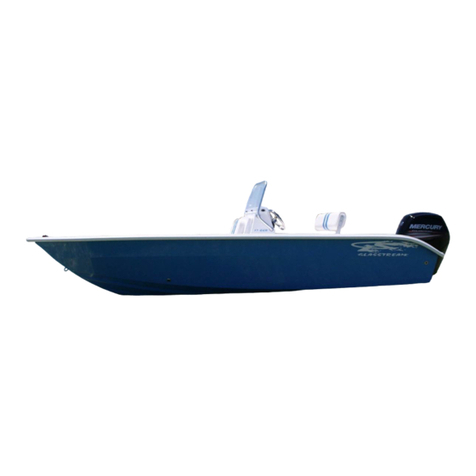
Chris-Craft 2015 21 Carina User manual

Preface
CHRIS-CRAFT CORPORATION
8161 15TH STREET EAST
SARASOTA, FL 34243 USA
1-(941) 351-4900
www.chriscraft.com
www.facebook.com/chriscraftboats
P-1P-1
Owner’s Manual For Model Year 2015
21 Carina
21 Capri
21 Capri
Inboard
CCB Part Number: 090-2416

Preface
On behalf of the entire team at Chris-Craft, thank you for selecting our
product. We appreciate the confidence that you have shown in our
company and products. As I’m sure you’ve discovered during the
selection and decision process, your Chris-Craft has been designed,
engineered and built with care and precision.
Our unwavering commitment is to provide you, our customer, with the
finest quality boat available. The information in this owner’s manual
has been assembled to assist you with the operation of your Chris-Craft
for your maximum safety and enjoyment. Please read this manual
completely and always operate your boat safely and courteously.
We all wish you many years of boating fun and safety.
Sincerely,
Stephen Heese
President
P-2P-2

Preface
Prepare For Underway - Checklist
START PLANNED ACTIVITIES
This checklist is designed to guide the owner to start and stop a safe boating experience.
Date:___________________ Time:__________________
________ Ensure that all required documents are on board.
________ Ensure that the boat, engines, fuel load, etc. have been checked and all systems are
absolutely ready for your planned activities.
________ Ensure that all life-saving equipment is in safe operating condition and easily accessible.
Show passengers where the equipment is located. Ensure they are able to use everything.
________ Check that there is enough fuel on board for the planned cruise. Allow for changes due to
adverse weather or other delays. Use 1/3 of the fuel to reach your destination, use 1/3 to re-
turn and keep 1/3 in reserve. If possible start the activities with a full fuel tank.
________ A Float Plan has been created and left with a responsible person.
________ Weather report ensures conditions are safe and within your experience level and capabilities.
________ Remove and properly stow all canvas that will not be used for the planned activities.
________ Turn on battery switches and check electrical service to the helm and all necessary areas.
________ Turn on the engine room blowers and operate them for four minutes. (The engine room
blowers should be operated when the boat is not on plane and the engines are running).
________ Check the engine compartment for gasoline vapors.
________ Check bilges for water that should not be there and that they are free of loose objects.
________ Ensure that the engine cooling seacocks are open.
________ Ensure that the outdrives are NOT in the FULL UP position.
________ Start the engines and immediately check that the oil pressure is in a safe operating range.
________ Check all engine instruments when the engines reach operational temperatures.
________ While the engines are at idle speed, pull the stop switch lanyard to ensure it is operational
and that your passengers are familiar with its use.
________ Turn on electronic equipment after engines have been started.
________ Check that the steering system is operational.
________ Check that the electrical system, horn, navigational lights and bilge pumps are operational.
________ A passenger safety brief has been completed.
________ Food and potable water is on board as necessary for planned activities.
________ Ensure that all charts on board are up-to-date for the planned boating area.
________ At least one passenger is on board that is able to operate the boat in an emergency.
________ Visual distress signals are current, accessible and properly stowed.
Comments and Notes
___________________________________________________________________________________
___________________________________________________________________________________
___________________________________________________________________________________
___________________________________________________________________________________
___________________________________________________________________________________
P-3P-3

Preface
Secure All Systems - Checklist
STOP PLANNED ACTIVITIES
This check list is designed to guide the owner to start and stop a safe boating experience.
Date:___________________ Time:__________________
________ Secure boat in your slip with all dock tie lines normally used to secure your boat.
________ Shut down both engines.
________ Raise outdrives to normal position for leaving the boat unattended.
________ Notify the person responsible for acting on your float plan that you have returned and that all
is in order.
________ Shut down all electronic equipment.
________ Turn off the engine room blowers.
________ Turn off all battery switches and check that the electrical service has been shut off to the
helm and to all other areas.
________ Check the engine compartment for gasoline vapors.
________ Check bilges for water that should not be there.
________ Check bilges for loose objects.
________ Check that the automatic bilge pumps are not running.
________ Plug in shore power cords and check alternating current system panel.
________ Install all canvas necessary to protect your unattended boat.
________ Check bilges for water that should not be there and that it is still free of loose objects.
________ Ensure that the engine cooling seacocks and all seacocks not in use are closed.
________ Check the electrical system, horn, navigational lights and bilge pumps to determine that all
are not operational with the battery switches off.
________ Remove any food and potable water that is not properly stored.
________ Ensure that all charts on board are properly stored and ready for next cruise.
________ Notify the marina to refuel both tanks to capacity.
Comments and Notes
___________________________________________________________________________________
___________________________________________________________________________________
___________________________________________________________________________________
___________________________________________________________________________________
___________________________________________________________________________________
___________________________________________________________________________________
___________________________________________________________________________________
___________________________________________________________________________________
___________________________________________________________________________________
___________________________________________________________________________________
P-4P-4

Preface
Your CHRIS-CRAFT Owner’s Manual has been written to include a number
of safety instructions to assure the safe operation and maintenance of your
boat. These instructions are in the form of WARNING and CAUTION
statements. The following definitions apply:
All instructions given in this book are as seen from the stern looking
toward the bow, with starboard being to your right, and port to your left.
A glossary of boating terms is included in the Appendix.
IMPORTANT NOTE: Your boat uses internal combustion engines and
flammable fuel. Every precaution has been taken by CHRIS-CRAFT to
reduce the risks associated with possible injury and damage from fire or
explosion, but your own precaution and good maintenance procedures
are necessary in order to enjoy safe operation of your boat.
If for any reason you have trouble with your CHRIS-CRAFT Owner’s
Manual, or require replacement pages, please contact our Customer
Service department at the address on the cover page. We will be happy
to supply replacement pages at no charge. This manual has been compiled
to help you to operate your boat with safety and pleasure. It contains details
of the boat, the equipment supplied or fitted, its systems, and information on
its operation and maintenance.
Please read it carefully, and familiarize yourself with your CHRIS-CRAFT
before using it.
WARNING
CAUTION
Hazards or unsafe practices which could result in
minor personal injury, or product and property damage.
HAZARDS OR UNSAFE PRACTICES WHICH COULD
RESULT IN SEVERE PERSONAL INJURY OR DEATH.
P-5P-5

Preface
If this is your first boat, or you are changing to a type of boat you are not
familiar with, for your own comfort and safety, please ensure that you
obtain handling and operating experience before assuming command of
the craft. Your dealer or national sailing federation or yacht club will be
pleased to advise you of local sea schools, or competent instructors.
Owner’s manuals for the installed equipment on your boat have also
been provided for your reference. They have been stored in a valise that
is included in your new boat. Please read this information, and also hand
them over to the new owner when you sell the boat.
PLEASE KEEP THIS MANUAL IN A SECURE
PLACE AND PRESENT IT TO THE NEW
OWNER WHEN YOU SELL THE BOAT.
NOTICE
P-6P-6

Page
1-1
1-2
1-3
1-4
1-5
1-5
1-5
1-7
1-8
2-1
2-2
2-4
2-9
2-10
2-11
2-11
2-11
2-11
2-13
2-14
2-14
2-15
2-16
2-16
2-16
2-17
2-18
2-18
2-19
2-20
2-20
2-20
2-21
2-22
2-23
2-23
2-23
2-24
2-24
2-24
2-25
2-27
CHAPTER 1 Introduction…………………………………………………………………………...…....
The Owner’s Manual……………………………………………………………………………...…....
What This Manual Covers……………..……………………………………………………………....
General Specifications…………………………………………………………………………………
Performance……………………………………………………………………………...………..……
Weight Conversions …………………………………………………………………………………...
Engine Performance ……………………………………………………………………………...…...
Design Category………………………………..…………………………………………..……….....
Component Manufacturers………………………….……………………………………..………….
CHAPTER 2 Safety and Operations……………………..……………………...………………...……
Warnings, Cautions and Notices……………………………………………………………………..
Index of Warning Placards and Decals …….……………………………………………………….
Boating Safety………………………………………………………………………………………….
General Safety Precautions……………………………………………………………….……….….
Boating Courses ……………………………………………………………………………………….
Basic Seamanship……………………………………………………………………….………….….
Visual Obstructions……………………………………………………………………………………..
Meeting Situations.…...…………………………………………………………………………..…….
A Boater’s Guide to Federal Requirements and Safety Tips...……………………………………
U.S. Coast Guard Boating Safety Contact Information…………………………………………….
Supplemental Federal, State and Local Regulations………………………………………..……..
Accident Reporting………………………………………………………………………………...…...
Rendering Assistance…………………………………………………………………………..……...
Vessel Maintenance…………………………………………………………………………………....
Load Capacity………………………...………………………………………………………………...
Coast Guard Approved Safety Equipment…………………………………………..…………..…..
PFD Considerations…………………………………………………………………………………….
Personal Flotation Devices (PFDs) ..……………………………………………………………..…..
Types of PFDs ………………………..……………………………………………………………..….
Foam Class PFDs …………………………………………………………………….……………..…
Inflatable Class PFDs ……………………………………………………………………..……….….
Hybrid Class PFDs …………………………………………………………………………………..…
PFD Considerations …………………………………………………………………………………....
Additional Equipment …………………………………………………………………………………..
Visual Distress Signals ………………………………………………………………………………...
Storage Of VDFs...………………………………………………………………………………..........
Disposal …………………………………………………………………………………………………
Emergencies ……………………………………………………………………………………………
Medical ……………………………………………………………………………………………….....
Getting Help …………………………………………………………………………………………….
Carbon Monoxide ……………………………………………………………………………………...
Man Overboard ………………………………………………………………………………….……..
ii
Table Of Contents

Page
2-29
2-29
2-29
2-30
2-30
2-31
2-32
2-32
2-33
2-33
2-34
2-34
2-35
2-36
2-37
2-38
CHAPTER 2 Safety and Operations (Continued)
Boat Systems Discussed In This Chapter…………………………………………………………..
Safety System - Fireboy…………….……………………………………………………………….
Helm Station..…………………………………………………………………………………….…….
Switch Identification…………………………………………………………………………………...
Underwater Lighting…………………………………………………………………………………...
Engine Compartment VA and VB……………………………………………………………………
Engine Compartment VB Inboard……………………………………………………………………
Seacocks and Thru Hulls……………………………………………………………………………..
Garboard Drain Plug…………………………………………………………………………………..
Bilge Pumps…………………………………………………………………………………………….
General Maintenance Schedule for Bilge Pumps………………………………………………….
Fuel Systems…………………………………………………………………………………………..
Fuel System Components…………………………………………………………………………….
Fuel Tank.………………………………………………………………………………………………
Fuel Gauges……………………………………………………………………………………………
Engine…………………………………………………………………………………………………..
Engine Throttle…………………………………………………………………………………………
Side Mount Shifters……………………………………………………………………………………
Engine Instruments…………………………………………………………………………………….
Selectable Exhaust…………………………………………………………………………………….
Engine Compartment Blower…………………………………………………………………………
Bennett Trim Tabs……………………………………………………………………………………..
Lenco Trim Tabs……………………………………………………………………………………….
Sanitizing The Fresh Water Transom Shower System……………………………………………
Using The Fresh Water Transom Shower…………………………………………………………..
3-2
3-2
3-4
3-4
3-8
3-10
3-11
3-13
3-13
3-14
3-15
3-16
3-16
3-17
3-19
3-19
3-20
3-20
3-21
3-22
3-23
3-24
3-28
3-30
3-31
Fires……………………………………………………………………………………………….…….
Classes of Fires ……………………………………………………………………………………….
Compliant Fire Extinguishers ………………………………………………………………………..
Required Number of Portable Fire Extinguishers ………………………………………………….
Fire Extinguisher Maintenance and Service ……………………………………………………….
Operation Of The Fireboy Fire Extinguisher ……………………………………………………….
Safety at Sea ……………………………………………………………………………………….….
Mechanical Failures …………………………………………………………………………………..
Shallow Water Dangers ………………………………………………………………………………
Running Aground …………………………………………………………………………...…….…..
Flooding, Sinking, and Capsizing …………………………………………………………...………
Collisions …………………………………………………………………………………………...….
Lighting Precautions ………………………………………………………………………………….
Fueling……..……………………………………………………………………………………………
After Fueling……………………………………………………………………………………………
Fueling Summary and Check List…………………………………………………………………...
iiii
CHAPTER 3 - Systems 3-1
Table Of Contents

Page
Transom Shower Fresh Water System…………………………………………………………….
Transom Shower System Troubleshooting………………………………………………………..
Electrical System Safety…………………………………………………………………………….
VA Electrical System………………….………………………………………...……………………
VB Electrical System…………………………………………………………………………………
DC Electrical System…………………………………………………………………………………
Battery Powered Systems…………………………………………………………………………...
DC Wiring Color Codes……………………………………………………………………………...
DC Electrical System Troubleshooting Hints………………………………………………………
Troubleshooting Tools……………………………………………………………………………….
Connecting and Disconnecting A Shore Power Chord…………………………………………..
Starting and Stopping The Engine………………………………………………………………….
Sunbrella Marine Tops ……………………………………………………………………………...
General Or Light Cleaning…………………………………………………………………………..
Heavy Cleaning For Stubborn Stains and Mildew………………………………………………...
How To Clean Clear Vinyl Eisenglass Boat Windows……………………………………………
Maintenance and Caring Of Stainless Steel……………………………………………………….
Maintenance and Caring Of Anodized Aluminum…………………………………………………
Cleaning and Maintenance Of Teak………………………………………………………………..
Entertainment Equipment……………………………………………………………………………
Compass……………………………………………………………………………………………….
Optional Ski Tow Location…………………………………………………………………………..
Engine Room Plumbing And Fuel Hose Routing………………………………………………….
Winter Storage Check List…………………………………………………………………………...
Spring Commissioning……………………………………………………………………………….
Vinyl Windows……………………………………………………………………………………...…
Canvas…………………………………………………………………………………………………
Painted Surfaces……………………………………………………………………………………..
Gelcoat Finish………………………………………………………………………………………...
Stainless Steel And Anodized Aluminum……..……………………………………………………
Teak……………………………………………………………………………………………………
Upholstery……………………………………………………………………………………………..
All Boat Water Systems……………………………………………………………………………...
Checklist For Winterizing Mercruiser Engine……………………………………………………...
Checklist For Winterizing Volvo Engine……………………………………………………………
Checklist For Winterizing Diesel Engine…………………………………………………………...
3-32
3-33
3-34
3-35
3-36
3-37
3-38
3-41
3-43
3-44
3-45
3-46
3-47
3-47
3-47
3-50
3-51
3-52
3-53
3-54
3-55
3-56
3-57
4-2
4-4
4-8
4-9
4-12
4-13
4-17
4-18
4-21
4-23
4-24
4-26
4-28
CHAPTER 3 Systems (Continued)
iiiiii
Table Of Contents
CHAPTER 4 Storage And Commissioning…………………………………………………………… 4-1

Page
APPENDIX A ….. Warranty Information ……………………………………………………………..
Thru..
APPENDIX B ….. Coast Guard Accident Report ……………………………………………………
Thru..
APPENDIX C ….. Float Plan ……………………………………………………………………………
Thru..
APPENDIX D ….. Water Skiing ………………………………………………………………………..
Thru..
APPENDIX E ….. Maintenance Log Forms ………………………………………………………….
Thru..
APPENDIX F ….. Navigational Aids ……..……………………………………………………………
Thru..
APPENDIX G ….. Electrical Drawings ……………………………………………………………….
Thru..
APPENDIX H ….. Glossary of Nautical Terms …..………………………………………………….
Thru..
A-1
.....A-7
B-1
.....B-8
C-1
….C-3
D-1
.....D-2
E-1
.....E-3
F-1
.....F-2
G-1
..G-9
H-1
.....H-6
iviv
APPENDIX INFORMATION
Table Of Contents
The Way It Was!
Chris Craft Barrel Back

Page
vv
Figure 1-1 …. Carina and Capri General Specifications.………………………………………………..
Figure 1-2 …. Carina and Capri General Specifications….…………………………………………...…
Figure 1-3 …. CE Certification Plate……...………………………………………..………..……………..
Figure 1-4 …. Australian Builder’s Plate……………………………………………..…………………….
Figure 1-5 …. NMMA Certification Decal...………………………………………..………..……………..
Figure 2-1 .... “Danger”……………………………………………………………………………………….
Figure 2-2 ..… “Warning”…………………………………………………………………………………….
Figure 2-3 ..… “Caution”……………………………………………………………………………………..
Figure 2-4 ..… “Notice”……………………………………………………………………………………...
Figure 2-5 ..… “Explosion”…………………………………………………………………………………..
Figure 2-6 ..… “Chemical or Hot Water Hazard”.………………………………………………………..
Figure 2-7 ..… “Eye Protection”…………………………………………………………………………….
Figure 2-8 ..… “Fire”………………………………………………………………………………………….
Figure 2-9 ..… “Poison”……………………………………………………………………………………...
Figure 2-10 … “Vapor”……………………………………………………………………………………….
2-11a thru 2-11z … All Signs & Labels……………………………………………………………...….….
Figure 2-12 … Crossing Situations……………………………………………………….………………...
Figure 2-13 ... Overtaking Situations……………………………………………………………………….
Figure 2-14 ... Head On Situations…………………………………………………………………………
Figure 2-15 ... Overtaking Situations……………………………………………………………………….
Figure 2-16 ... Man Overboard……………………………………………………………………………...
Figure 2-17 … P.A.S.S. (Pull, Aim, Squeeze, Sweep)…………………………………………………...
Figure 2-18 ... Fireboy Engine Room………………………………………………………………………
Figure 2-19 ... Fireboy Helm Station……………………………………………. ………………………...
Figure 2-20 ... Fireboy Electrical System…………………………………………………………………..
Figure 2-21 … Gasoline Vapors Warning Label…………………………………………………………..
Figure 2-22 ... Spilling Gasoline Warning…………………………………………………………………..
Figure 3-1 .… Fire Extinguisher Location………………………………………………………………….
Figure 3-2 …. System Indicator…………………………………………………………………………….
Figure 3-3 …. Engine Room Fire Extinguisher……………………………………………………………
Figure 3-4 .… VB Helm Station Switch Panel and Instrument Panel…………………………………..
Figure 3-5 …. VB Helm Station Switch Panel with Electronics Package………………………………
Figure 3-6 …. VA Helm Station Switch and Gauge Panel………………………………………………
Figure 3-7 …. VB Helm Console and Switch Panel……………………………………………………...
Figure 3-8 …. VA Helm Console and Switch Panel……………………………………………………...
Figure 3-9 …. VB Helm Console and Instrument Panel…………………………………………………
1-4
1-4
1-6
1-6
1-6
2-2
2-2
2-2
2-2
2-3
2-3
2-3
2-3
2-3
2-3
2-9
2-12
2-12
2-12
2-12
2-28
2-29
2-31
2-31
2-31
2-37
2-38
3-3
3-3
3-3
3-4
3-4
3-4
3-5
3-5
3-6
List Of Figures

Page
Figure 3-10 … Underwater Electrical Drawing……………………………………………………………
Figure 3-11 … Underwater Lighting Breaker Panel………………………………………………………
Figure 3-12 … Underwater Lighting Switch Panel………………………………………………………..
Figure 3-13 … Underwater Lights (2) Location……………………………………………………………
Figure 3-14 … Mercruiser Engine Installation……………………………………………………………..
Figure 3-15 … Volvo Engine Installation…………………………………………………………………...
Figure 3-16 … Battery Switch……………………………………………………………………………….
Figure 3-17 … Mercruiser Stern Drive Trim Pump………………………………………………………..
Figure 3-18 … Mercruiser Trim Pump and Battery Tray Location………………………………………
Figure 3-19 … Bilge Pump, Float Switch and Transducer Location…………………………………….
Figure 3-20 … VBI Thru Hull Exhaust……………………………………………………………………...
Figure 3-21 … VBI Engine Mount and Seacock Location……………………………………………….
Figure 3-22 … VBI Bilge Pump and Float Switch Location………………………………………………
Figure 3-23 … VBI Transmission…………………………………………………………………………...
Figure 3-24 … VBI Storage Basket Location………………………………………………………………
Figure 3-25 … Engine Front View…………………………………………………………………………..
Figure 3-26 … Engine Room View………………………………………………………………………….
Figure 3-27 … Seacock and Water Strainer Location……………………………………………………
Figure 3-28 … Steering Cylinder and Tiller………………………………………………………………..
Figure 3-29 … Trim Tab Zinc Plate…………………………………………………………………………
Figure 3-30 … Transducer Location………………………………………………………………………..
Figure 3-31 … Seacock Location…………………………………………………………………………...
Figure 3-32 … Garboard Drain Plug………………………………………………………………………..
Figure 3-33 … 30 AMP Circuit Breaker - 24 Hour Essential Circuits Module - Battery Switch………
Figure 3-34 … Bilge Pump and Float Switch Location VA and VB Models…………………………….
Figure 3-35 … Bilge Pump and Float Switch Location VBI Model………………………………………
Figure 3-36 … Diesel Fuel Fill Deck Plate…………………………………………………………………
Figure 3-37 … Gasoline Fuel Fill Deck Plate……………………………………………………………...
Figure 3-38 … Fuel Tank Hose and Electrical Connections……………………………………………..
Figure 3-39 … VB Fuel Gauge..…………………………………………………………………………….
Figure 3-40 … VB Ignition Switch…………………………………………………………………………..
Figure 3-41 … VA Fuel Gauge……………………………………………………………………………...
Figure 3-42 … VA Ignition Switch…………………………………………………………………………..
Figure 3-43 … VA Mercruiser Side Mount Shifter………………………………………………………...
Figure 3-44 …VA Teleflex Side Mount Shifter……………………………………………………………
Figure 3-45 … VB Volvo Side Mount Shifter………………………………………………………………
Figure 3-46 … VB Teleflex Side Mount Shifter…………………………………………………………...
3-8
3-9
3-9
3-9
3-10
3-10
3-10
3-10
3-10
3-10
3-11
3-11
3-11
3-11
3-12
3-12
3-12
3-12
3-12
3-12
3-12
3-13
3-13
3-14
3-15
3-15
3-17
3-17
3-18
3-19
3-19
3-19
3-19
3-20
3-20
3-20
3-20
vivi
List Of Figures

Page
Figure 3-47 … Selectable Exhaust System………………………………………………………………..
Figure 3-48 … Bilge Blower Motor Location……………………………………………………………….
Figure 3-49 … Volvo Engine Room Blower Hoses……………………………………………………….
Figure 3-50 … Mercruiser Engine Room Blower Hoses………………………………………………….
Figure 3-51 … Trim Plate With Zinc………………………………………………………………………..
Figure 3-52 … Bennett Trim Pump and Reservoir………………………………………………………..
Figure 3-53 … Trim Tab Zinc………………………………………………………………………………..
Figure 3-54 … Trim Tab Control Switches………………………………………………………………...
Figure 3-55 … Trim Tab Switches………………………………………………………………………….
Figure 3-56 … Trim Tab System Overview………………………………………………………………..
Figure 3-57 … Trim Tab System Overview………………………………………………………………..
Figure 3-58 … Bennett Trim Tab Installation……………………………………………………………...
Figure 3-59 … Bennett Trim Tab Zinc Plate Installed…………………………………………………….
Figure 3-60 … Lenco Trim Tab Electrical Diagram………………………………………………………
Figure 3-61 … Lenco Trim Tab Parts Description………………………………………………………...
Figure 3-62 … Lenco Cylinder Parts Description…………………………………………………………
Figure 3-63 … VB Shower Head and Water Fill Location………………………………………………..
Figure 3-64 … Transom shower Pump and Filter Location……………………………………………...
Figure 3-65 … Six Gallon Water Tank Location…………………………………………………………..
Figure 3-66 … Shower Installation with Mercruiser Engine……………………………………………...
Figure 3-67 … Shower Installation with Volvo Engine……………………………………………………
Figure 3-68 … Shower Head and Water Fill Locations…………………………………………………..
Figure 3-69 … Water Tank, Hose Filter Pump and Shower……………………………………………..
Figure 3-70 … VA Switch Panel…………………………………………………………………………….
Figure 3-71 … VA DC Breaker Panel……………………………………………………………………...
Figure 3-72 … VA DC Panel Location……………………………………………………………………..
Figure 3-73 … VB Switch Panel…………………………………………………………………………….
Figure 3-74 … VB DC Breaker Panel………………………………………………………………………
Figure 3-75 … VB DC Breaker Panel Location……………………………………………………………
Figure 3-76 … VB DC Breaker Panel……………………………………………………………………...
Figure 3-77 … VA Fuel Gauge Location…………………………………………………………………...
Figure 3-78 … VB Fuel Gauge Location…………………………………………………………………...
Figure 3-79 … Battery Location……………………………………………………………………………..
Figure 3-80 … Battery Switch Location…………………………………………………………………….
Figure 3-81 … Battery Switch, 24 Hour Breaker Box and Main Breaker……………………………….
Figure 3-82 … Battery Switch, 24 Hour Breaker Box and Main Breaker Electrical Drawing………...
Figure 3-83 … Battery Charger Located On Engine Room Firewall…………………………………….
3-22
3-23
3-23
3-23
3-24
3-24
3-24
3-24
3-24
3-26
3-27
3-27
3-27
3-28
3-28
3-29
3-31
3-32
3-32
3-32
3-32
3.32
3-33
3-35
3-35
3-35
3-36
3-36
3-36
3-36
3-37
3-37
3-38
3-38
3-39
3-39
3-42
viivii
List Of Figures

Page
Figure 3-84 … Description Drawing of Battery Charger………………………………………………….
Figure 3-85 … The Fusion IP-700……………………….………………………………………………….
Figure 3-86 … Internal iPod Deck…………………………………………………………………………..
Figure 3-87 … VB Sub Woofer Location…………………………………………………………………...
Figure 3-88 … VA Sub Woofer Location…………………………………………………………………...
Figure 3-89 … VB Helm Station…………………………………………………………………………….
Figure 3-90 … Ritchie Compass……………………………………………………………………………
Figure 3-91 … Ski Tow Ready For Use……………………………………………………………………
Figure 3-92 … Ski Tow Location……………………………………………………………………………
Figure 3-93 … Ski Tow Location…………………………………………………………………………..
Figure 3-94 … Ski Tow Container With Drain Fitting……………………………………………………..
Figure 3-95 … Engine Room Hose Routing……………………………………………………………….
3-42
3-54
3-54
3-55
3-55
3-55
3-55
3-56
3-56
3-56
3-56
3-57
viiviii
List Of Figures

Page
4-11
Figure 4-1 .... Windshield and Console Cover……………………………………………………………
Figure 4-2 .... “How To” Gelcoat DVD…………………………………………………………………….
Figure 4-3 .... Well Maintained 36 Launch………………………………………………………………..
Figure 4-4 .... Teak Maintenance Forward………………………………………………………………..
Figure 4-5 .... Teak Maintenance Aft……………………………………………………………………...
Figure 4-6 .... Muffler Drain Plug…………………………………………………………………………..
Figure 4-7 …. Strainer Drain Plug………………………………………………………………………….
Figure 4-8 …. Kohler Generator Installation………………………………………………………………
Figure 4-9 …. Volvo Gasoline Engine Installation……………………………………………………….
Figure 4-10 … Mercruiser Gasoline Engine Installation………………………………………………….
Figure 4-11 … Mercruiser Air Pump Installed……………………………………………………………..
Figure 4-12 … Mercruiser Air Pump………………………………………………………………………..
Figure 4-13 … Mercruiser Port Drain Plugs………………………………………………………………..
Figure 4-14 … Mercruiser Starboard Drain Plug………………………………………………………….
Figure 4-15 … See Mercruiser Owner’s Manual For Water Drain Procedure………………………….
Figure 4-16 … Mercruiser Raw Water Pump……………………………………………………………...
Figure 4-17 … Mercruiser Air Pump Receiver…………………………………………………………….
Figure 4-18 … Mercruiser Engine Distribution Housing Drain Location………………………………..
Figure 4-19 … Mercruiser Engine Fuel Cooler…………………………………………………………….
Figure 4-20 … Volvo EVC Engine Port Side View………………………………………………………..
Figure 4-21 … Volvo EVC Engine Starboard Side View…………………………………………………
Figure 4-22 … Volvo EVC Engine Front View…………………………………………………………….
Figure 4-23 … Volvo Engine Closed Cooling System…………………………………………………….
Figure 4-24 … Volvo Engine Heat Exchanger…………………………………………………………….
Figure 4-25 … Volvo Engine Lower End Cap Of Heat Exchanger……………………………………...
Figure 4-26 … Volvo Diesel D3 Engine Closed Cooling Drain Points………………………………….
Figure 4-27 … Volvo Diesel D3 Engine Sea Strainer…………………………………………………….
Figure 4-28 … Volvo Diesel D3 Engine and Stern Drive Side View…………………………………….
Figure 4-29 … Volvo Diesel D3 Engine Sea Strainer Location………………………………………….
Figure 4-30 … Volvo Diesel D6 Engine Side View………………………………………………………..
Figure 4-31 … Volvo Duo Prop Stern Drive Side View…………………………………………………...
Figure 4-32 … Volvo D6 Diesel Cooling Water Mix……………………………………………………….
Figure 4-33 … Volvo D6 Diesel Cooling Water Fill Cap Level Indicator………………………………..
Figure 4-34 … Volvo D6 Diesel Fresh Water Cooling System Draining………………………………..
Figure 4-35 … Volvo D6 Diesel Sea Water Cooling System Draining………………………………….
Figure 4-36 … Kohler Diesel Generator Model 5EFKOD Installed.…………………………………….
ixix
List Of Figures

Page
1-4
1-5
1-7
1-8
2-17
2-19
2-20
2-20
2-20
2-23
2-30
2-30
3-5
3-6
3-7
3-33
3-41
3-44
3-48
3-49
3-53
Table 1.1 ... General Specifications ……………………………………………………………...
Table 1.2 ... Weight Conversions…………..……………………………………………………..
Table 1.3 ... Design Category……………………………………………………………………..
Table 1.4 ... Vendor Directory……………………………………………………………………..
Table 2.1 ... Minimum Required Safety Equipment.………………………………………….…
Table 2.2 ... Types of PFDs ………………………………………………………………...…….
Table 2.3 ... PFD Minimum Buoyancy Requirements - Foam.………………………………...
Table 2.4 ... PFD Minimum Buoyancy Requirements - Inflatable……………………………..
Table 2.5 ... PFD Minimum Buoyancy Requirements - Hybrid………………………………...
Table 2.6 ... Visual Distress Signals.……………………………………………………………..
Table 2.7 ... Class of Fire and Extinguisher Types……………………………………………..
Table 2.8 ... Minimum Portable Fire Extinguishers Required………………………………….
Table 3.1 ... Switch Identification and Amperage Ratings……………………………………..
Table 3.2 … Switch Identification and Amperage Ratings…………………………………….
Table 3.3 ... Switch Identification Markers And Descriptions………………………………….
Table 3.4 … Transom Shower Water System Trouble Shooting………………………………
Table 3.5 … Engine And Battery Wire Colors……………………………………………………
Table 3.6 … DC Current Electrical Troubleshooting Chart……………………………………..
Table 3.7 … Canvas Cleaning……………………………………………………………………..
Table 3.8 … Canvas Cleaning…………………………………………………………………….
Table 3.9 … Cleaning Supplies……………………………………………………………………
xx
List Of Tables
Complete List Of Tables - All Chapters

Introduction
Introduction
Chapter 1
A Chris-Craft is a blend of the best of classic design, distinctive styling and superb
naval engineering focused on producing truly seaworthy boats. Chris-Craft’s dedication
to craftsmanship and quality totally differentiates its boats from others and represents
the company’s enduring devotion to its proud past. America’s best naval architects,
designers, boat builders and furniture makers are committed to continuous new
product development and technology and maintaining Chris-Craft as America’s only
premium boat brand, thus setting standards beyond perfection.
1-11-1

Introduction
American Boat & Yacht Council
613 Third Street, Suite 10
Annapolis, MD 21403
Phone: (410) 990-4460
Fax: (410) 990-4466
https://www.abycinc.org
The Owner’s Manual
This manual is written to meet the recommendations of Technical Information Report T-24, Owner’s
Manuals, published by the American Boat and Yacht Council (ABYC) and the International Standard
ISO 10240: Small Craft – Owner’s Manual.
In the United States, the American Boat and Yacht Council is a marine industry-based standards
organization that publishes Standards and Recommended Practices for Small Craft. The book is an
extensive collection of construction and design standards for small craft that is used as a guide by boat
builders throughout the world. For more information contact:
This manual is compiled to aid in the operation of the Chris-Craft line of boats in a safe and enjoyable
manner. It contains information on the systems, equipment operation, and general maintenance on each
model of boat. Many of the systems in the Chris-Craft line are similar among the various models, where
differences do occur, they will be pointed out and explained.
This manual provides important up-to-date information on various systems at the time that this vessel
was manufactured. Specifications of engines and other components are all subject to change without
notice. The data contained herein is subservient to the manufacturers’ manuals of the numerous compo-
nents, installed in this vessel. If a discrepancy exists between this manual and the component manual,
the component manual takes precedence.
This owner’s manual is not a course on boating safety or seamanship. If this is your first boat, or if you
are changing to a type of boat you are not familiar with, for your own comfort and safety, please ensure
that you obtain handling and operating experience before assuming command of the craft.
Always use trained and competent people for maintenance, repair, or modifications. The boat builder
cannot be held responsible for modifications Chris*Craft has not approved.
Any craft, no matter how strong it may be, can be severely damaged if not used properly. This is not
compatible with safe boating. Always adjust the speed and direction of the craft to the sea conditions.
Ensure that the anticipated wind and sea conditions corresponds to the design category of your craft,
and that you and your crew are able to handle the craft in these conditions.
All persons should wear suitable buoyancy aid (life jacket/personal flotation device) when operating your
boat. It is incumbent upon the owner/operator to stay informed of any changes and/or
modifications that affect any component of this vessel and/or the safety of the vessel.
A COPY OF THIS OWNER ‘S MANUAL IS LOCATED ON THE CHRISCRAFT WEB SITE.
http://chriscraft.com/main/owners/owners-manuals.aspx
1-21-2

Introduction
1-31-3
Chris-Craft Boats are proudly manufactured in the United States Of America by the:
Chris-Craft Corporation
8161 15th Street East
Sarasota, FL 34243
Phone: (941) 351-4900
Fax: (941) 358-3776
What This Manual Covers
This Manual covers the following Chris-Craft models:
1. 21 Carina
2. 21 Capri
3. 21 Inboard Capri
Chris Craft offers various upgrades and options. In most cases the options are discussed in this manual.
When you take possession of your Chris-Craft you will receive the appropriate manuals associated with
the options you may have chosen.
As the owner/operator it is your responsibility to familiarize
yourself with the specific characteristics of your boat.
The features and specifications discussed in this manual are subject to change
without notice. Chris-Craft reserves the right to discontinue any model and make
changes, at any time, in colors, equipment, specifications, materials, and prices.
Chris-Craft is not obligated to make, or provide, similar changes to any model
previously sold.
NOTICE

Introduction
Figure 1-2. 21 Carina, Capri (I/0) & IB)Figure 1-1. 21 Carina, Capri (I/0) & IB)
General Specifications
See more at: http://www.chriscraft.com/
Table 1-1. General Specifications
Model Boat Models VA, VB, VB IB
Beam (Waterline) 7’ 6” 2.29 m
Fuel Capacity (Carina & Capri) 34 gallons 129 liters
Fuel Capacity (VB Inboard}
Transom Angle 15 Degrees .
Maximum Persons 6 persons (7 Persons Australian) .
Water Capacity 50 gal 189 ltr
Draft VB Inboard 32 1/4” 76.8 cm
Bridge Clearance 46.5” 1.8 m .
Height Overall 4’ 11” 1.47 m
Freeboard at Half Length 27” 68.5 cm
Freeboard Aft 17.5” 44.5 cm
Freeboard Forward 31.5” 80 cm
Dry Weight 2,913 lbs 1,351 kg
36 gallons 136 liters
1-41-4
Center Of Gravity (forward of transom keel) 5’ 10” 1.78 m
Waterline Length 17’ 2” 5.23 m
Beam (Maximum) 7’ 11” 2.41 m
Beam (Transom) 6’ 10” 2.08 m
Overall Length (with swim platform) 21’ 2” 6.45 m
Overall Length (with swim platform) 19’ 7” 5.98 m
Draft (Prop Shaft Raised) VA & VB 17” 43.2 cm
Deadrise 18 degrees .
Draft (Prop Shaft Lowered) VA & VB 34” 86.4 cm
Table of contents
Other Chris-Craft Boat manuals
Popular Boat manuals by other brands
Rinker
Rinker Cruisers Owner's/operator's manual

Canadian Electric Boat Company
Canadian Electric Boat Company Fantail 217 owner's manual

Yamaha
Yamaha SUPERJET 700 2006 Owner's/operator's manual

Regal
Regal 2300 owner's manual

RS SAILING
RS SAILING RSCAT 14 Rigging manual
CORRECT CRAFT
CORRECT CRAFT 80128 owner's manual
