CiA 733 User manual

User
User’
’s Manual
s Manual
733_V0.95
Please read instructions thoroughly before operation and retain
Please read instructions thoroughly before operation and retain it for future reference.
it for future reference.

Firmware:
Firmware:
BootLoader: 0.1.0.0
Kernel: 0.1.2.3
HtmlFile: 0.1.1.6
Mpeg4: 0.1.0.4
Application:
Application: 0.1.2.2

The lightning flash with arrowhead symbol, within an equilateral
triangle, is intended to alert the user to the presence of uninsulated
“dangerous voltage” within the product’s enclosure that may be of
sufficient magnitude to constitute a risk of electric shock to persons.
This exclamation point within an equilateral triangle is intended to
alert the user to the presence of important operating and
maintenance (servicing) instructions in the literature accompanying
the appliance.
CE Mark
This apparatus is manufactured to comply with the radio interference
requirements of EN55022, CISPR 22, and AS/NZS CISPR 22.
CAUTION:
CAUTION:
To reduce the risk of electric shock, do not expose this apparatus to rain or moisture.
Only operate this apparatus from the type of power source indicated on the label. Failure to do so
may cause injury or death by electric shock and invalidates the warranty.
CAUTION
CAUTION
RISK OF ELECTRIC SHOCK
RISK OF ELECTRIC SHOCK
DO NO OPEN
DO NO OPEN

1.1 FEATURES ------------------------------------------------------------------------------------------------------------
1.2 PACKAGE CONTENTS --------------------------------------------------------------------------------------------
1.3 SPECIFICATION -----------------------------------------------------------------------------------------------------
1.4 PANEL ------------------------------------------------------------------------------------------------------------------
2.1 SYSTEM CONNECTION -------------------------------------------------------------------------------------------
2.2 CONNECT DVR TO VIDEO WEB SERVER ------------------------------------------------------------------
2.3 SOFTWARE INSTALLATION ------------------------------------------------------------------------------------
2.4 IP SETTING AND LAN CONNECTION ------------------------------------------------------------------------
2.5 CONNECT VIA INTERNET ---------------------------------------------------------------------------------------
3.1 SOFTWARE OPERATION -------------------------------------------------------------------------------------
3.2 PLAYBACK OPERATION -------------------------------------------------------------------------------------
3.3 ADVANCED SETTING -----------------------------------------------------------------------------------------
Network --------------------------------------------------------------------------------------------------------
DDNS ----------------------------------------------------------------------------------------------------------
SNTP ------------------------------------------------------------------------------------------------------------
FTP --------------------------------------------------------------------------------------------------------------
Mail --------------------------------------------------------------------------------------------------------------
General ---------------------------------------------------------------------------------------------------------
Peripheral ------------------------------------------------------------------------------------------------------
Account --------------------------------------------------------------------------------------------------------
File Path --------------------------------------------------------------------------------------------------------
Schedule Record --------------------------------------------------------------------------------------------
Trigger ----------------------------------------------------------------------------------------------------------
Information ----------------------------------------------------------------------------------------------------
Log File ---------------------------------------------------------------------------------------------------------
Event Record List -------------------------------------------------------------------------------------------
DVR PIN CONNECTION ----------------------------------------------------------
PTZ PIN CONNECTION -----------------------------------------------------------
IE BROWSER ----------------------------------------------------------------------
DDNS APPLY ----------------------------------------------------------------------
1
1
2
3
4
5
6
6
10
11
14
15
15
16
16
17
17
18
18
19
19
20
20
22
22
22
23
24
25
26

NOTE :
Please check the package contents to make sure that all accessories are included.
1
Crossover LAN cable Adapter
Video Web Server Manual & Quick Start
Licensed Software AP
1) Support MPEG4 compression format for real-time video stream
2) Compression format (MPEG4 / JPEG) is selectable for different network bandwidth
and applications
3) Support video / audio recording
4) Support alarm / motion trigger recording
5) Adjustable motion detect sensitivity
6) Whenever alarm system triggered, video streaming or pictures will be uploaded
over FTP,
email as an instant notification.
7) Support 3G & GPRS system for remote surveillance with mobile phone
8) Support TCP/IP, PPPoE, DDNS and DHCP for network connection
9) Support DDNS and function as a router
10) Support NTSC system / PAL system / AUTO detect video input signals
11) Support video access by APs (software) or HTML pages (IE explorer)
12) Full event record list for easy search and quick playback
13) Support schedule recording
14) Support multiple user access levels with security protection
15) Support multiple on-line users (up to 10 users)
16) Support watermark function
17) Support de-blocking and de-interlace function
18) Support watch dog function for automatic network reconnection.
19) ANR will reactivate recording function automatically when network is reconnected
20) Easy to upgrade firmware

Design and specification are subject to change without notice.
Support TCP/IP, PPPoE, DDNS and DHCP for network connectionNetwork Connection
YesWatermark
YesDe-interlace
YesDe-blocking
YesMotion Trigger Recording
3 adjustable factorsMotion Detection
500 mACurrent consumption
DC 12VPower Source
Password protectionSecurity
Triggered by GPIO Input, Action: E-mail video/images or
video/images upload to FTP site's specific accounts
Trigger & Action
Video through put : Up to 30(NTSC), 25(PAL) frames/ secondPerformance
704x480, 352x240 (NTSC) / 704x576, 352x288 (PAL)Resolution
TCP/IP, ICMP, SMTP, FTP, HTTP, DHCP, DDNS, PPPoE, SNTPProtocols
Brightness, Contrast, Saturation and HueVideo Adjustment
MPEG4 / JPEGImage Compression
Ethernet (10/100 Base-T)Network Interface
YesRS-485 Port
YesWatch dog
2 inputs / 1 outputAlarm Input
1 channel audio inputAudio Input
1 channel for analog & digital products,
1.0 Vp-p 75 composite, BNC
Video Input
2

1) LAN:
Connect Video Web Server to the Internet or LAN with cable or connect
directly to PC with standard pass through cable.
2) VIDEO INPUT (1 channel):
Connect to video source, such as camera or DVR video output.
3) AUDIO INPUT (1 channel):
Connect to audio source, such as camera audio output.
4) ALARM I/O (optional for advanced applications):
Connect control devices, such as PTZ, DVR and external alarm signal input.
5) POWER:
Plug in the supplied power adaptor (12V / 500mA).
6) RESET (at the bottom of Video Web Server):
Press this button to default setting.
3

1)
1) Power:
Power: Connect to DC 12V regulated adapter.
2)
2) Video and Audio Input:
Video and Audio Input: Connect video and audio outputs of camera or DVR…etc.
Take DVR as an example, after connection, set the baud rate and ID of the DVR.
Make sure that the baud rate and ID as same as the settings of the VIDEO WEB
SERVER.
3)
3) Software Installation:
Software Installation: Install the software on PC.
4)
4) IP Setting:
IP Setting: Connect PC with Video Web Server for IP setting (Local Connection).
5)
5) LAN:
LAN: After IP setting, connect Video Web Server with ADSL or CABLE MODEM.
6)
6) ALARM I/O (Optional for advanced applications):
ALARM I/O (Optional for advanced applications):
Connect to control devices, such as PTZ, DVR and external alarm signal input.
[ CONNECTION APPLICATIONS ]
[ CONNECTION APPLICATIONS ]
4

1)
1) DVR Baud Rate and ID Setting:
DVR Baud Rate and ID Setting:
Set the baud rate and ID of the DVR. Make sure that the baud rate and ID as
same as the settings of the VIDEO WEB SERVER.
2)
2) DVR and Video Web Server PIN Connections (Optional for advanced
DVR and Video Web Server PIN Connections (Optional for advanced application):
application):
Connect DVR PIN with VIDEO WEB SERVER PIN.
For detailed PIN connection, please refer to “Appendix #2 ” and “Appendix #3”
PIN 1, 6:
PIN 1, 6: RS485-A, RS485-B
Use RS485-A & RS485-B serial communication signals to control digital units
just like that to control DVR.
PIN 4, 9:
PIN 4, 9: ALARM INPUT
Use PIN 4,,9 to receive the alarm input and then trigger Video Server to send
mail to users for auto e-mail warning system.
PIN 5:
PIN 5: GND
Ground
PIN 2, 3:
PIN 2, 3: NORMAL OPEN, NORMAL COM
Use PIN 2 or 3 to trigger external device to act.
Please see the example picture below for 1CH/4CH DVR.
It’s recommended to solder these joints
5

1) Put the attached CD into a CD-ROM and it will start to install application
program into PC.
2) Click “ “ twice.
3) Click “Finish” button to complete the setup.
And users will see the icon “ “ on the desktop.
Note:
Note:
After physical connection, please go to the next two sections for IP address settings.
Steps:
Start Control Panel Network and Internet Connections Network
Connections Local Area Connection Status Properties Internet Protocol
(TCP/IP).
1) Network setting for PC. (This following instruction is based on Win XP O/S.
If the O/S is Win 2000, the setup procedure is similar to that on Win XP O/S.)
6

Before changing this properties setting, please write down the original network
setting in order to recover the original setting after “Section 3.2 VIDEO WEB
SERVER SETTING”.
Click on “Use the following IP address” , set IP address and subnet mask.
The IP address should be like 192.168.1.XXX.
The setting of “XXX” could be set from 1 to 254 except 10 ( Because
192.168.1.10 is the video web server default IP ); the subnet mask is always
255.255.255.0.
2) After PC IP SETTING, connect PC or Notebook with Video Web Server by
crossover LAN cable.
Note:
Note:
In some operation environments, users might need the standard CAT5 cable.
3) To configure the Server IP, please click twice to enter the setup.
4) Key in User Name, Password, and Server IP (The default setting of User Name
and Password are admin; Server IP 192.168.1.10, Port : 80 ). Then click the
green button to connect.
RJ
RJ-
-45
45
POWER
POWER
7

5) When users see the following screen, means successfully logged in the program
of the Video Web Server. Click “System Config” to set up.
6) In the Peripheral setting, set baud rate, ID and model which users want to remote
control later.
Press “APPLY” to enable the change after the setting.
The setting of “Baud rate” , “ID” should be the same as the setting of the external
device users want to remote control.
10
Camera 01
Camera 01 Camera 02
Camera 02
Camera 03
Camera 03 Camera 04
Camera 04
!
!
"#$%%&
"#$%%&
8

7) Click on the Network, set server IP, gateway, and net mask which are provided
from local ISP ( internet service provider ), web server, stream port, and IP type.
Press “APPLY” to enable the change after the setting.
8) Disconnect PC and Video Web Server, and then connect Video Web Server to
the Internet with RJ-45.
RJ
RJ-
-45
45
POWER
POWER
MODEM
MODEM
Dynamic IP:
Dynamic IP: Note:
For dynamic IP (PPPoE, DHCP)circumstances,
users need apply “Host Name” first. Please refer
to “APPENDIX #4 – DDNS APPLY”
Static IP:
Static IP:
9
1) Change PC network setting to the original setting and link PC to the internet.
( Since the PC IP setting has been changed, now it must recover to the original
setting for connecting to internet ).
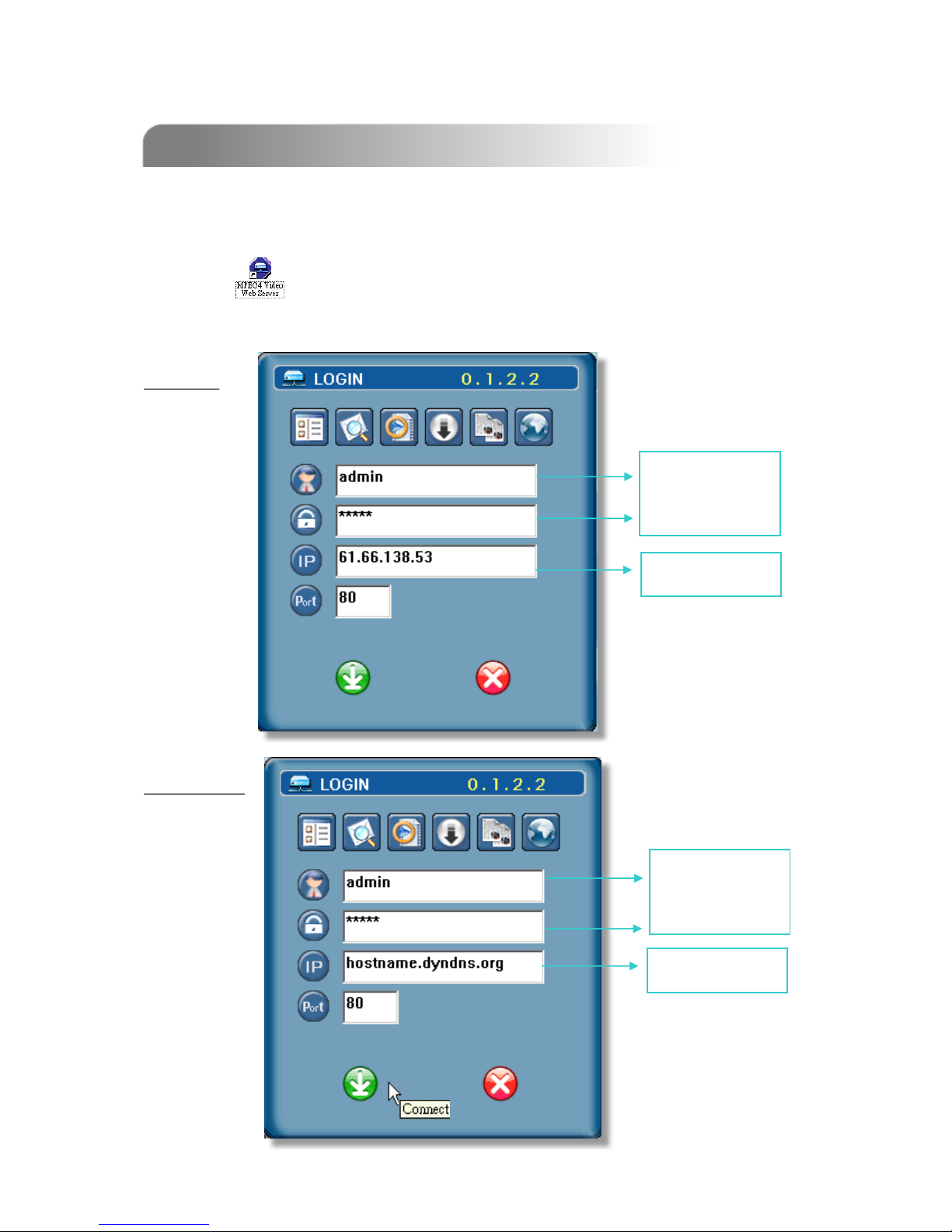
2) Click twice and enter “User Name”, “Password”, “Static IP”, and “Port”.
Then click the green button to connect.
NOTE : The default username and password are both “admin”.
Dynamic IP:
Dynamic IP:
Static IP:
Static IP:
Static IP address
USER NAME
AND
PASSWORD OF
VIDEO WEB
SERVER
DDNS HOST
USER NAME
AND
PASSWORD OF
VIDEO WEB
SERVER
10

1) Click twice to enter Login page.
2) Key in “User Name”, “ Password”, and “Server IP” (Static IP) or “Host
name”(Dynamic IP). Click the green button to connect.
After physical connection and network setting of the video web server.
Please following the illustrations in this section for software operation.
3) LOGIN AP Icon Explanation:
Address Book:
Address Book: Users could
press this button to add
frequently-used IP address or
choose any preset IP address
to access the Video Server.
Search:
Search: Search available IP
address of the external
device in local area. And
modify the network settings of
the external device.
Player:
Player: Users could press this
button to access and play the
recorded files saved in the PC.
Upgrade Firmware:
Upgrade Firmware: Users could
press this button to get the
provided firmware and then
press the “Upgrade” button.
Login Setting:
Login Setting: Users could
press this button to set the
transmission type (UDP or
TCP) and decode type
(MPEG4 or JPEG).
NOTE:
TCP: Suitable for stable network with
higher bandwidth.
UDP: Suitable for unstable network
with lower bandwidth.
Copy:
Copy: Users could press this
button to copy all the software
installation files, so users could
keep all the settings of video
web server for next software
installation on other PC.
Take static IP as an example.
Take static IP as an example.
11

4) Introduction of Basic Operation:
a. Image transfer rate per second
b. Data transfer rate
c. Video only / Audio only / Both
Video and Audio
d. Connect / Disconnect
e. Image adjusting : Brightness /
Contrast / Saturation / Hue
f. Snapshot : press this button to
have a snapshot of the image
which will be saved in the
designated destination.
g. Record : press this button, the
video web server will start to
record, and recording files will
be saved to PC. Each recording
file can up to 18,000 frames,
when the recording file
capacity is full, the new
recorded file will be saved to
the second file.
Besides, if the HDD space is
less than 200MB, the program
will stop recording.
h. System config: press this button
to enter the setting page of the
video web server.
i. Number of online users
Video Web Server Control Panel
Video Web Server Control Panel
Digital Device Control Panel ~ DVR
Digital Device Control Panel ~ DVR
(For example, 4 channel DVR)
j. CH1-4
k. PIP/+, QUAD/-
l. Zoom, Lock, Record ( in DVR HD ), Search
m. Stop, Rewind, Fast Forward , Pause, Slow, Play
n. Menu / up / down / left / right
o. Enter
p. TURBO:
To speed up menu selecting or the control of the PTZ camera under video web server,
users could activate "Turbo" function by clicking this button. Users are allowed to change
the turbo steps from 1 to 10.
Ex. If users activate the TURBO function, and set "3" for turbo step, then when users
press one of the button up/down/left/right, one mouse click will as if click 3 times.
Camera 01
Camera 01 Camera 02
Camera 02
Camera 03
Camera 03 Camera 04
Camera 04
!
!
"#$%%&
"#$%%&
bcid e f gh
j.
k.
l
l
m.
m.
n.
o. p.
a
12

Digital Device Control Panel ~ PTZ
Digital Device Control Panel ~ PTZ
(For example, PTZ)
j. Preset 1 ~ 16
k. AUTO
l. Zoom Tele
m. Zoom Wide
n. Focus Near
o. Focus Far
p. Max Zoom In
q. Max Zoom Out
r. Menu / up / down / left / right
s. Enter
t. TURBO:
To speed up menu selecting or the control of the PTZ camera under video web server,
users could activate "Turbo" function by clicking this button. Users are allowed to change
the turbo steps from 1 to 10. .
Ex. If users activate the TURBO function, then when users press one of the button
up/down/left/right, one mouse click will function as if click 3 times
.
r.
s. t.
j.
k. l. m
.
n. o. p. q.
Hot Point
Hot Point : Users could control our own brand PTZ camera screen to a specific
point by using cursor.
13

Please find a recording file in the PC and double click on it to playback.
a. Snapshot
b. Stop
c. Pause
d. Fast Rewind (1X, 2X, 4X, 8X, 16X)
e. Slow Rewind (1X, 1/2X, 1/4X, 1/8X, 1/16X)
f. PLAY (1X)
g. Slow Playback (1X, 1/2X, 1/4X, 1/8X, 1/16X)
h. Fast Forward (1X, 2X, 4X, 8X, 16X)
i. OSD ( show / hide )
j. Config. Setting (File path for snapshot, text color, progress color, De-
interlace, De-block, Record Style, Size, Resolution, Date)
k. Open Previous File
l. Open Next File
m. Watermark:
Press ” “ button to proof the authenticity of the backup video. If the recorded
video had been altered, the video image will turn to light red and the playback
will be paused.
Note:
Note:
When users pause the playback picture, users could press “d” button to go to the previous image, or
press “h” button to go to the next image.
'
' !'$%%&
!'$%%& CH 1
CH 1
67
67
352
352
288
288 192.168.1.53
192.168.1.53
a.
a. b.
b. c.
c. d.
d. e.
e. f.
f. g.
g. h.
h. i.
i. j.
j. k.
k. l.
l. m.
m.
14

1) Press “System Config ” button to enter the “System Config” page.
2) In this “System Config” page, users could select the different functions to set up.
3) After setting, please press “APPLY” button to save the settings.
4) System setting includes:
Network, DDNS, SNTP, FTP, Mail, General, Peripheral, Account, File Path, Schedule
Record, Trigger, Information, Log File, Event Record List.
1) Click on “Network”, and choose the
IP TYPE (Static IP, PPPoE, DHCP).
2)
2) Static IP:
Static IP:
Please refer to “Section 2.4 IP
SETTING AND LAN CONNECTION”.
3)
3) PPPoE
PPPoE and DHCP:
and DHCP:
Please refer to “Section 2.4 IP
SETTING AND LAN CONNECTION”.
Network
Network
*Web Port: DVR port. * Stream Port: Transmitting video and audio.
IP: 61.66.138.53
15

1) DDNS is a service for
transforming dynamic IP to
corresponding to a specific
“Hostname”.
2) Enable the DDNS function.
Key in the “DDNS username”
into “User Name”.
Key in the “DDNS password”
into “Password”.
Key in the “Hostname” into
“Domain”.
Choose the “DDNS System
Name”.
DDNS
DDNS
1)
1) SNTP
SNTP (Simple Network Time
(Simple Network Time
Protocol)
Protocol)” is for time setting. So it
also concerns to “Schedule Record.
2)
2) GMT (Greenwich Mean Time)
GMT (Greenwich Mean Time):
Once users choose the time zone,
the video web server will adjust the
local area time of system
automatically.
Server Name
Server Name:
Users could simply use the
automatically SNTP server, or could
set up another SNTP server.
3)
3) Sync Server Time
Sync Server Time:
The video web server will
synchronize the time in the video
web server and the network time.
SNTP
SNTP
Note:
Note: DHCP and PPPoE network types need to apply DDNS service to get “Hostname”
to correspond to dynamic IP address. For detailed DDNS setting, please refer to
“Section 4.1 DDNS APPLY”.
Note:
Note: This product does not have RTC, it need to get time on the Internet and use
software to calculate time.
16
This manual suits for next models
1
Table of contents


