CiA TDC26 User manual

ITALIANO
ENGLISH
USER’S MANUAL
(for circuits 619aMA-2 622aMA-2 ).xx, .xx
GSM phone dialers
with vocal messages
TDC26 - TDC36 - TM26GSM -
TM66GSM - ERMES2

2626
12 28 12 28
2
2626
3737
2828
2626
2
1
1515
ABS metallic
140mm 280mm 285mm
115mm 230mm 95mm
29mm 96mm 17mm
Index
Chapter 1 Introduction 35
1.1 Functional characteristics ...............................................................................................35
1.2 Technical characteristics.................................................................................................35
Chapter 2 Installation 36
2.1 Connections TDC26 .......................................................................................................36
2.2 Connections ERMES2,TM66GSM,TDC36,TM26GSM...................................................37
2.3 Connections TM600Pantenna (ERMES2-TM66GSM-TM26GSM-TDC36) ....................39
2.4 Connections antenna (ERMES2-TM66GSM-TM26GSM-TDC36)..................................39
2.5 Connections line GSM ....................................................................................................39
Chapter 3 Programming 40
3.1 Accessing programming .................................................................................................41
3.2 Directory .........................................................................................................................42
3.3 Voice messages .............................................................................................................44
3.4 Text messages................................................................................................................46
3.5 Channels.........................................................................................................................47
3.6 Outputs ...........................................................................................................................49
3.6.1 Mode ..................................................................................................................49
3.6.2 Reference input..................................................................................................50
3.6.3 Pulse duration ....................................................................................................50
3.7 Parameters .....................................................................................................................51
3.7.1 Answerphone .....................................................................................................51
3.7.2 Tone Detector.....................................................................................................51
3.7.3 Tones / Pulses....................................................................................................52
3.7.4 Remote Control..................................................................................................52
3.7.5 Language selection............................................................................................53
3.7.6 Beep no Registr. ................................................................................................53
3.8 Codes ...........................................................................................................................53
3.9 Info ...........................................................................................................................55
3.10 Reset to default settings .................................................................................................55
Chapter 4 Operation 56
4.1 General operation ...........................................................................................................56
4.2 Local control ...................................................................................................................57
4.2.1 STOP CYCLE ....................................................................................................57
4.2.2 STOP ALL CYCLES ...........................................................................................57
4.2.3 OUTPUT COMMANDS......................................................................................58
4.2.4 INPUT STATUS..................................................................................................59
4.2.5 OUT OF ORDER................................................................................................59
4.2.6 IN SERVICE.......................................................................................................60
4.2.7 TELEPHONE .....................................................................................................60
4.2.8 REMOTE CONTROL .........................................................................................61
34 35
1 Introduction
1.1 Functional characteristics
1.2 Technical characteristics
!Built-in microphone
!Dual Band GSM module
!Delay on input singularly programmable
!Possibility to assign each phone number singularly to one channel, some channel or to all channels
!Antiopening and antitearing protection tamper
!Multiple languages: Italian, English, French, German, Spanish, Portuguese
!Indication of the intensity of GSM signal and of the telephone manager
!Message repetitions and calling cycles settable
!'Out of order' function
!CLIP function :One output control by one ring (call without answer) from one phone number in SMS address book,
with automatic return of confirming ring
IntroductionTDC26-TDC36-TM26GSM-TM66GSM-ERMES2- User’s manual
12Vdc±10%
Remote ambient listening
SMS messagges (128 char.)
On display SMS messages (16 char.) for
monitoring of the input and output's state
Operators codes settable (Code MASTER and
Code COMMANDOS)
Channels
Power supply voltage
Max current consumption
Consumption in st/by
Vocal messages (16 sec.)
State vocal messages (2 sec.) for inputs / outputs
state monitoring
Address book
Bay for battery
Power supply / power set
Input channels programmable as pulse or as status
mode, conditionable to the others
Input channels conditioning INT
Programmable relay outputs
100mA open collector programmable outputs
External box
Dimensions (W)
Dimensions (H)
Dimensions (D)
400mA
70mA
16numers
12V7Ah (not included)
AL1 (included)
TDC36TDC26 TM26GSM TM66GSMERMES2
with function speakerphone

2626
12 28 12 28
2
2626
3737
2828
2626
2
1
1515
ABS metallic
140mm 280mm 285mm
115mm 230mm 95mm
29mm 96mm 17mm
Index
Chapter 1 Introduction 35
1.1 Functional characteristics ...............................................................................................35
1.2 Technical characteristics.................................................................................................35
Chapter 2 Installation 36
2.1 Connections TDC26 .......................................................................................................36
2.2 Connections ERMES2,TM66GSM,TDC36,TM26GSM...................................................37
2.3 Connections TM600Pantenna (ERMES2-TM66GSM-TM26GSM-TDC36) ....................39
2.4 Connections antenna (ERMES2-TM66GSM-TM26GSM-TDC36)..................................39
2.5 Connections line GSM ....................................................................................................39
Chapter 3 Programming 40
3.1 Accessing programming .................................................................................................41
3.2 Directory .........................................................................................................................42
3.3 Voice messages .............................................................................................................44
3.4 Text messages................................................................................................................46
3.5 Channels.........................................................................................................................47
3.6 Outputs ...........................................................................................................................49
3.6.1 Mode ..................................................................................................................49
3.6.2 Reference input..................................................................................................50
3.6.3 Pulse duration ....................................................................................................50
3.7 Parameters .....................................................................................................................51
3.7.1 Answerphone .....................................................................................................51
3.7.2 Tone Detector.....................................................................................................51
3.7.3 Tones / Pulses....................................................................................................52
3.7.4 Remote Control..................................................................................................52
3.7.5 Language selection............................................................................................53
3.7.6 Beep no Registr. ................................................................................................53
3.8 Codes ...........................................................................................................................53
3.9 Info ...........................................................................................................................55
3.10 Reset to default settings .................................................................................................55
Chapter 4 Operation 56
4.1 General operation ...........................................................................................................56
4.2 Local control ...................................................................................................................57
4.2.1 STOP CYCLE ....................................................................................................57
4.2.2 STOP ALL CYCLES ...........................................................................................57
4.2.3 OUTPUT COMMANDS......................................................................................58
4.2.4 INPUT STATUS..................................................................................................59
4.2.5 OUT OF ORDER................................................................................................59
4.2.6 IN SERVICE.......................................................................................................60
4.2.7 TELEPHONE .....................................................................................................60
4.2.8 REMOTE CONTROL .........................................................................................61
34 35
1 Introduction
1.1 Functional characteristics
1.2 Technical characteristics
!Built-in microphone
!Dual Band GSM module
!Delay on input singularly programmable
!Possibility to assign each phone number singularly to one channel, some channel or to all channels
!Antiopening and antitearing protection tamper
!Multiple languages: Italian, English, French, German, Spanish, Portuguese
!Indication of the intensity of GSM signal and of the telephone manager
!Message repetitions and calling cycles settable
!'Out of order' function
!CLIP function :One output control by one ring (call without answer) from one phone number in SMS address book,
with automatic return of confirming ring
IntroductionTDC26-TDC36-TM26GSM-TM66GSM-ERMES2- User’s manual
12Vdc±10%
Remote ambient listening
SMS messagges (128 char.)
On display SMS messages (16 char.) for
monitoring of the input and output's state
Operators codes settable (Code MASTER and
Code COMMANDOS)
Channels
Power supply voltage
Max current consumption
Consumption in st/by
Vocal messages (16 sec.)
State vocal messages (2 sec.) for inputs / outputs
state monitoring
Address book
Bay for battery
Power supply / power set
Input channels programmable as pulse or as status
mode, conditionable to the others
Input channels conditioning INT
Programmable relay outputs
100mA open collector programmable outputs
External box
Dimensions (W)
Dimensions (H)
Dimensions (D)
400mA
70mA
16numers
12V7Ah (not included)
AL1 (included)
TDC36TDC26 TM26GSM TM66GSMERMES2
with function speakerphone

37
2.2 Connections ERMES2 / TM66GSM / TDC36 / TM26GSM
Installation
2 Installation
2.1 TDC26 connections
This connection allows the input and output
of the burglar alarm whether with the
electronic key as with phone dial.
NOTE: If you use only the phone dial is
necessary to connect only the output C and
NC of the Relay1 of the phone dial
on Key terminals of the exchange.
Burglar
center unit
Key
electronic
ENSURE WIRE IS ENTIRELY
SPREAD BEFORE CYCLE
POWER ON
Relaay 2
(optionally)
only in
ERMES2
TDC36
Switch
ERMES2 / TM66GSM / TDC36 / TM26GSM
IN2
IN3
IN4
IN5
IN6
IN1
OUT1
INT1
+ Sir.
+ Int.
OUT3
OUT4
OUT5
OUT6
Int1 K1Int2
12V
SETUP
K4 K6
K2 K3 K5 C1 NC1NA1
Tamper U4 U6
U2 U3 U5
OUT2
Burglar
central unit
Net
230V~
50Hz
Black
Red
White
This connection, if used, consents
to send to one of inputs (K1,K2...) A positive one
of reference in presence of main voltage 230 Vac.
Setting up in the programming the input like
“Positive Level”, to lacking the mains voltage
telephone dialer will send the message of relative alarm.
ATTENTION!
In order to use the
positive outputs ‘+ Sir’ e ‘+ Int.’
Of burglar central the negative
must be in common
to the feeding of
ERMES2 / TM66GSM
Electronic
key
only in
ERMES2
This connection allows
the insertion and the not
insertion at a distance of
burglar central unit united to
uses of electronic key.
only in
ERMES2 / TM66GSM
Channel 2÷6
activation example
TDC26-TDC36-TM26GSM-TM66GSM-ERMES2- User’s manual
TDC26
12Vcc
Int1
OUT2
IN K1
IN K2
NA
JP
C
OUT1
*
In serie
alla 24h
INT2
Select with jumper
the operation
of clipJP
OUT1 NC
Connect with delicacy
the connector male of the antenna
on the connector of the phone
like the figure.
Key of
Access to the
programming
by means RESET
Diode
1N4004 or
similar
Example of
activation channel 2
36
The antennas can
be distanced ulteriorly
by the PR-ANT 5mt cable
(DO NOT INSTALL MORE
THAN ONE)
The base of the TDC26 can be mounted
on a standard wall-mounted box 503-type.”.
1. Through the use of any GSM phone is
necessary to eliminate the access code
(code PIN) that qualifies the Sim card use.
2. Insert Sim Card in the module according
to the rounded corner.
3. NOT FORCED THE SIM CARD

37
2.2 Connections ERMES2 / TM66GSM / TDC36 / TM26GSM
Installation
2 Installation
2.1 TDC26 connections
This connection allows the input and output
of the burglar alarm whether with the
electronic key as with phone dial.
NOTE: If you use only the phone dial is
necessary to connect only the output C and
NC of the Relay1 of the phone dial
on Key terminals of the exchange.
Burglar
center unit
Key
electronic
ENSURE WIRE IS ENTIRELY
SPREAD BEFORE CYCLE
POWER ON
Relaay 2
(optionally)
only in
ERMES2
TDC36
Switch
ERMES2 / TM66GSM / TDC36 / TM26GSM
IN2
IN3
IN4
IN5
IN6
IN1
OUT1
INT1
+ Sir.
+ Int.
OUT3
OUT4
OUT5
OUT6
Int1 K1Int2
12V
SETUP
K4 K6
K2 K3 K5 C1 NC1NA1
Tamper U4 U6
U2 U3 U5
OUT2
Burglar
central unit
Net
230V~
50Hz
Black
Red
White
This connection, if used, consents
to send to one of inputs (K1,K2...) A positive one
of reference in presence of main voltage 230 Vac.
Setting up in the programming the input like
“Positive Level”, to lacking the mains voltage
telephone dialer will send the message of relative alarm.
ATTENTION!
In order to use the
positive outputs ‘+ Sir’ e ‘+ Int.’
Of burglar central the negative
must be in common
to the feeding of
ERMES2 / TM66GSM
Electronic
key
only in
ERMES2
This connection allows
the insertion and the not
insertion at a distance of
burglar central unit united to
uses of electronic key.
only in
ERMES2 / TM66GSM
Channel 2÷6
activation example
TDC26-TDC36-TM26GSM-TM66GSM-ERMES2- User’s manual
TDC26
12Vcc
Int1
OUT2
IN K1
IN K2
NA
JP
C
OUT1
*
In serie
alla 24h
INT2
Select with jumper
the operation
of clipJP
OUT1 NC
Connect with delicacy
the connector male of the antenna
on the connector of the phone
like the figure.
Key of
Access to the
programming
by means RESET
Diode
1N4004 or
similar
Example of
activation channel 2
36
The antennas can
be distanced ulteriorly
by the PR-ANT 5mt cable
(DO NOT INSTALL MORE
THAN ONE)
The base of the TDC26 can be mounted
on a standard wall-mounted box 503-type.”.
1. Through the use of any GSM phone is
necessary to eliminate the access code
(code PIN) that qualifies the Sim card use.
2. Insert Sim Card in the module according
to the rounded corner.
3. NOT FORCED THE SIM CARD

38 39
2.4 Antenna connection (ERMES2 - TM66GSM - TDC36 -
TM26GSM)
2.5 Connection to the GSM network
Module GSM works with common SIM Card GSM. If to the ignition of the phone dialer it
comes visualized shielded following:
Once inserted card GSM, to the ignition of the combinatore, or in case of reset, comes
started the search of net GSM and the display it visualizes the following message:
To the term of the search, if the combinatore is connected to net GSM will come visualized
the state of the visualized recording like of continuation:
Low intensity of network
High intensity of network
The green LED “Status”, it indicates the control that the phone dialer verified on GSM module.
it means that it has not been inserted the SIM card to the inside of module GSM, or has
been inserted in wrong way. Therefore TO TURN OFF THE PHONE DIALER, and to proceed
to the indicated insertion of the SIM card like in the previous paragraphs.
The red LED "GSM" on the panel indicates the activity of module GSM;
!Led OFF: not operating
!Led ON: during one logon
!A flash to the second: GSM recorded and in wait
!Blinking: in inactivity or error condition
__ _INSERT SIM
05¥ TIM__
30¥ TIM__
Registration ..._
InstallationTDC26-TDC36-TM26GSM-TM66GSM-ERMES2- User’s manual
NOT FORCED THE SIM!!
ATTENTION:
THE SIM INSERTED COME OUT FROM THE
CIRCUIT OF 4MM
1.Through I use it of a whichever
telephone GSM is necessary to eliminate
the access code (code PIN) that enabled
the use of the card;
2.To insert the SIM card to the inside
of the module being held
account of the dulled angle.
NOTE: Not forced the SIM.
ANT GSM
only
ERMES2
2.3 Connections TM600P
IN2
IN3
IN4
IN5
IN1
Electronic
key
SK50
INT1
+ Sir.
+ Int.
only
for ERMES2
OUT3
OUT4
OUT5
OUT6
for ERMES2
and TM66GSM
Example of
activation
channel 2÷6
Int1 K1Int2
12V
SETUP
K4 K6
K2 K3 K5 C1 NC1NA1
Tamper U4 U6
U2 U3 U5
OUT2
IN6
OUT1
TM600P
Burglar
central
unit
TM600P
only
ERMES 2
and TDC36
Voltage
230V~
50Hz
Sectioning switch
This connection, if used,allows send to one
of the inputs (K1, K2 ...) one positive of the
reference in presence of the voltage of 230Vac.
With setting in programmation the input in
"Positive Level", when the power voltage of the
dialer will send the alarm message.
White
Red
Black
The antennas can be distanced
ulteriorly through extend it of 5
mt PR-ANT(NOT TO INSTALL
MORE THAN ONE IT EXTENDS).
ATTENTION!
In order to use the
positive outputs ‘+ Sir’ e ‘+ Int.’
Of burglar central the negative
must be in common
to the feeding of
ERMES2 / TM66GSM

3 Programmation
It is possible to operate the menus in two different modes:
!using the keys: or
!fino a visualizzare la voce desiderata
for example:
!and pressing: or
or
!using the fast selection button: (Programming)
NOTE In the manual, in most cases, the fast selection key method will be
used. In this manner, during the consultation of the manual, it will be
possible to utilise the sequence of keys beside each Paragraph to
quickly access the programming described within..
Once installation has been carried out and the combiner has been powered up,
select the desired language using the or and press the or .
The available languages ar
When on standby mode, having selected the combiner language, the combiners
display the status of the two input channels (CH1 is enabled and CH2 is disabled by
default) in rotation.
!This will be displayed:
which alternates with
Once inserted the SIM, the combinatore will carry out the recording to the net of
the telephone manager having visualized:
This is valid for both the Principal Menu, to access any submenu, and within any
of the various submenus, where it is moreover possible to utilise the fast selection
keys to select a given parameter, a given system, and so on.
It is possible in any case to abandon programming by keying or
e: Italian,English,French,Spanish,Portugues,German
Ready_.........
8-PROGRAMMING
Ch1 Rubrica Off
25¥ TIM
Ch1 Disabled
25¥ TIM
41
TDC26-TDC36-TM26GSM-TM66GSM-ERMES2- User’s manual
40
Programmation
!As soon as carried out the recording it comes visualized:
In order to activate a cycle of calls on a channel it is necessary that a number
telephone is qualified at least voice “Ch1 Rubric OFF” indicates that to channel 1 is
not associated some telephone number neither for the vocal calls neither for the
shipment of the SMS and therefore turns out not operating.
3.1 Accessing programming
Programming of the combiner is only permitted from the local keyboard by keying
the MASTER code. ( )
!Key in the code: (Default MASTER code)
!Press the button: (Programming)
!This will be displayed:
Programming of the combiner allows for:
!Voice Directory 16 telephone numbers to which the Voice Messages will be forwarded.
!Vocal Messages 3 of 11 seconds (common message, channel 1, channel 2) + 12 status messages
of 2 seconds each.
!Text Messages Input and output status descriptions.
!Channels Input, conditions and activation delay settings.
!Vocal Messages 6 (in the ERMES2 and TM66GSM) or 2 (in the TDC36, the TDC26 and the
of State TM26GSM) vocal messages of 15 second ones relati you to the activations of the
channels. 2 vocal messages of 2 second ones relati to you to the two states of
income INT. 12 (in the ERMES2 and TM66GSM) or 4 (in the TDC36, the TDC26
and the TM26GSM) vocal messages of 2 second ones relati to you to the two
states of every income 12 (in the ERMES2 and TM66GSM) or 4 (in the TDC36,
the TDC26 and the TM26GSM) vocal messages of 2 second relati to you to the
two states of every output.
!SMS Messages 6 (In the ERMES2 and nel TM66GSM) or 2 (in the TDC36, in TDC26 and nel
TM26GSM) SMS of 100 relative characters you alle activations goddesses
channels 2 SMS of 16 relative characters you ai two states dell' income INT.
12 (In the ERMES2 and in TM66GSM) or 4 (in TDC36, in TDC22 and in
TM26GSM) SMS of 16 relative characters you ai two states of every input.12 (In
the ERMES2 and nel TM66GSM) or 4 (nel TDC36, nel TDC26 and nel TM26GSM)
SMS of 16 relative characters you relati ai two states to you of every escape.
!Output Formulation of the outputs.
!Parameters The function parameters of the combiner are set out in this section.
!Codes Variation of the MASTER code and COMMAND code.
!Info Display of information on the combiner model and the firmware.
Init GSM .......
CH1 Rubric Off
__
__
10Y TIM
Ch1 Rubric Off
_PROGRAMMING
1-Rubric
43
In order to write the text of the name, it is sufficient to keep one of the keys
pressed in order to display in sequence the letters printed on the panel; the available
characters are as follows:
NOTE: To cancel a letter or number during memorisation, or to modify an
entry, use the or keys to choose the letter or number and use
the key to cancel it.
!Once the name of the telephone number has been stored, press the key and
then press the or .
!This will be displayed:
Press the or to assign the stored number to channel 1 and/or channel 2
respectively. To cancel the assignment, it is sufficient to key the channel number
once again.
Once the channel has been assigned, press the key once to go back, and
select the next number to be stored using the or .
Repeat the above procedure to store the other numbers.
NOTE: If no number is inserted in the directory and assigned to at least one of the
two channels (in the case of the second channel, CH2, this will have to be
enabled first), the combiner displays the following on the initial display:
!Once assigned one or more telephone channels to one or more numbers to
digitare the key
!This will be displayed:
!Press the button correspondent at the canal to which it is wanted to be assigned
the sms.
!This will be displayed:
Vocal call
Channel >--
Ch1 Rubric Off
25¥ TIM
SMS
Channel >--
SMS
Channel >1-
Programmation
ABCabc2
DEFdef3
JKLjkl5 MNOmno6
TUVtuv8 WXYZwxyz9
GHIghi4
PQRSpqrs7
?!,.:;”’<=>()1
+&@/%$_0
[spazio]
* *
42
3.2
In this menu it is possible to insert or modify the telephone numbers that the
combiner must call in case of activation of a channel.
!Key in the code: (Default MASTER code)
!Press the button: (Programming)
!Press the button: (Directory)
!This will be displayed
!Press the button: or
!This will be displayed:
!Press the button:
!This will be displayed
!Key the number to be stored and press the button
!Once the telephone number is stored, press the key
!This will be displayed:
!Press the button:
!This will be displayed:
!Key in the name to be stored
for example:
!Press the button::
NOTE: The maximum length of the name to be inserted is 16 characters.
Directory
Number 01
Num. 01
___
___
Number
Not Programmed
Number
>
_
Name
Num. 01
Name
Num.01 >
Name
Mr. Red >
TDC26-TDC36-TM26GSM-TM66GSM-ERMES2- User’s manual

In K1___ NO
* Play # Rec
_ ______
_ _____ _
In K1___ SI
* Play # Rec
_ ______
_ _____ _
In K2 NO
* Play # Rec
_ _________
_ _____ _
In K2___ SI
* Play # Rec
_ ______
_ _____ _
INT1 NO
* Play # Rec
__________
_ _____ _
INT1 SI
* Play # Rec
__________
_ _____ _
INT2 NO
* Play # Rec
__________
_ _____ _
INT2 SI
* Play # Rec
__________
_ _____ _
Out 1 NO
* Play # Rec
_ _________
_ _____ _
Out 1 SI
* Play # Rec
_ _________
_ _____ _
Out 2 NO
* Play # Rec
_ _________
_ _____ _
Out 2 SI
* Play # Rec
_ _________
_ _____ _
2 sec.
2 sec.
2 sec.
2 sec.
2 sec.
2 sec.
2 sec.
2 sec.
2 sec.
2 sec.
2 sec.
2 sec.
It marks it the income
not active channel 1
It marks it the income
active channel 2
It indicates the absence of the
voltage +12Volt on input INT1
It indicates the presence of the
voltage +12Volt on input INT1
It indicates the absence of the
voltage +12Volt on input INT2
It indicates the presence of the
voltage +12Volt on input INT2
OUT1 message for the
not active output
Status
Messages
It marks it the income
active channel 1
It marks it the income
not active channel 2
OUT1 message for the
active output
OUT2 message for the
not active output
OUT2 message for the
active output
COMMON Msg.
* Play # Rec
_
_ _____ _
Channel 1
* Play # Rec
_
_ _____ _
Channel 2
* Play # Rec
_
_ _____ _
Indication on the first line of the display Duration:
16 sec.
16 sec.
16 sec.
Operating:
It is transmitted for first during
one called of an alarm cycle
It follows active the common message
when channel 1
It follows active the common message
when channel 2
Allarm
messages
45
NOTE
The message sent during a call following the activation of a channel is
comprised of the common message, followed by the specific message of the
activated channel, the whole repeated several times (as indicated by the parameter
“Number of messages” (see para 3.7.5).
NOTA:In the ERMES2,TM66GSM models,the vocal messages of state are in
total 12 for input +4 for the output.
The status messages are used during remote control to signal the status of the
inputs and outputs and are transmitted following an activation or interrogation
command of the outputs, or following an interrogation command of the inputs.
: The display of the 6 channel ERMES2,TM66GSM,arrived at 6 channels.
Once recorded, select the next voice message to be stored using the or
keys ,and then press the or . And repeat the above procedure to store the
other messages.
NOTE: When a channel becomes alarmed, the combiner carries out a cycle of calls to
all the numbers inserted in the Voice Directory connected to the channel to
forward the relative Voice Message.The “Cycle Quantity” parameter
described below establishes how many times this cycle of calls must be
repeated.If " " is pressed during the sending of the voice message,
the number called is excluded from the directory of successive calls.
It is advisable therefore to insert a note at the end of recording the
Voice Message of the type: “… Key zero not to receive this alarm
message further”.
Programmation
44
Once assigned one or more telephone channels to one or more numbers to digitare
the key
!This will be displayed:
In this voice of the menù it is possible to insert the operation that the combinatore
executes when telephone call receives one.
3.3 Voice messages
The voice messages are those which the combiner uses to signal an alarm or the
status of the inputs and outputs to the user during a telephone connection
!Key in the code: (Default MASTER code)
!Press the button: (Programming)
!Press the button: (Voice Messages)
!This will be displayed:
!Press the button: (recording)
!This will be displayed:
!Premere il tasto: (playback)
!This will be displayed:
A table of the available voice messages is then reported, indicated in the upper
area of the display:
Clip
Off
COMMON Msg.
* Play # Rec
_
_ _____ _
COMMON Msg._
>>>>>>>>>>>>>>>>
COMMON Msg._
>>>>>>>>>>>>>>>>
TDC26-TDC36-TM26GSM-TM66GSM-ERMES2- User’s manual
OUT1 OFF --_ ______
OUT2 OFF --_ ______
OUT3 OFF --_ ______
OUT4 OFF --_ ______
OUT5 OFF --_ ______
OUT6 OFF --_ ______
OUTX ON --_ _______
Select the output 1
Select the output 2
Select the output 3
Select the output 4
Select the output 5
Select the output 6
It sendes a command ON on the selected output
5
4
3
2
1
6
7
OUTX OFF CR_ ______
It qualifies the answer call on the selected output
8
OUTX OFF --_ ______
It sendes a command OFF on the selected output
9
Off
Disable the CLIP
0

47
3.5 Channels
In this menu, it is possible to establish how the channels of the combiner must be
activated.
!Key in the code: (Default MASTER code)
!Press the button: (Programming)
!Press the button: (Channels)
!This will be displayed
!Press the button: or
!This will be displayed
!Press the button: or
!This will be displayed
Choose between the activation mode depicted in the table under which condition
the channel is alarmed, using the or keys. Then press the or .
CHANNEL SELECT
Channel 1
_
__
Channel
1-Activation
1
1-Activation
NC
Impulse
The channel is activated from the presence of a
positive 12Vcc to the input of the channel; the cycle
of calls comes started and carried out until the term,
if not interrupted through commandos..
The channel is activated from the absence of a
positive 12Vcc on the input of the channel; the cycle
of calls comes started and carried out until the term,
if not interrupted through commandos
The channel is activated from the presence
of a positive 12Vcc on the input of channel;il the cycle
of calls comes executed until the term if not interrupted
from a command or coming to lack
the positive one on the income
0
12V
Impulse NO
0
12V
Impulse NC
0
12V
Level NO
Level NC
0
12V
The channel is active to lacking the positive one 12Vcc
on the income of thechannel; the cycle of calls comes
activated and carriedout until the term, if not interrupted
through commandos or the restoration of the positive
one 12Vcc on the income
1-Activation
Not Active_
The active channel in no condition and on the first
one display of the combinatore is not come visualized:
Init GSM
Ch1 Disabled
Programmation
In K1 NO
* Play # Rec
_ ________
_ _____ _
In K1 SI
* Play # Rec
_ ________
_ _____ _
In K2 NO
* Play # Rec
_ ________
_ _____ _
In K2 SI
* Play # Rec
_ ________
_ _____ _
INT1 NO
* Play # Rec
_________
_ _____ _
INT1 SI
* Play # Rec
_________
_ _____ _
INT2 NO
* Play # Rec
_________
_ _____ _
INT2 SI
* Play # Rec
_________
_ _____ _
Out 1 NO
* Play # Rec
_ ________
_ _____ _
Out 1 SI
* Play # Re
_ ________
_ _____ _
Out 2 NO
* Play # Rec
_ ________
_ _____ _
Out 2 SI
* Play # Rec
_ ________
_ _____ _
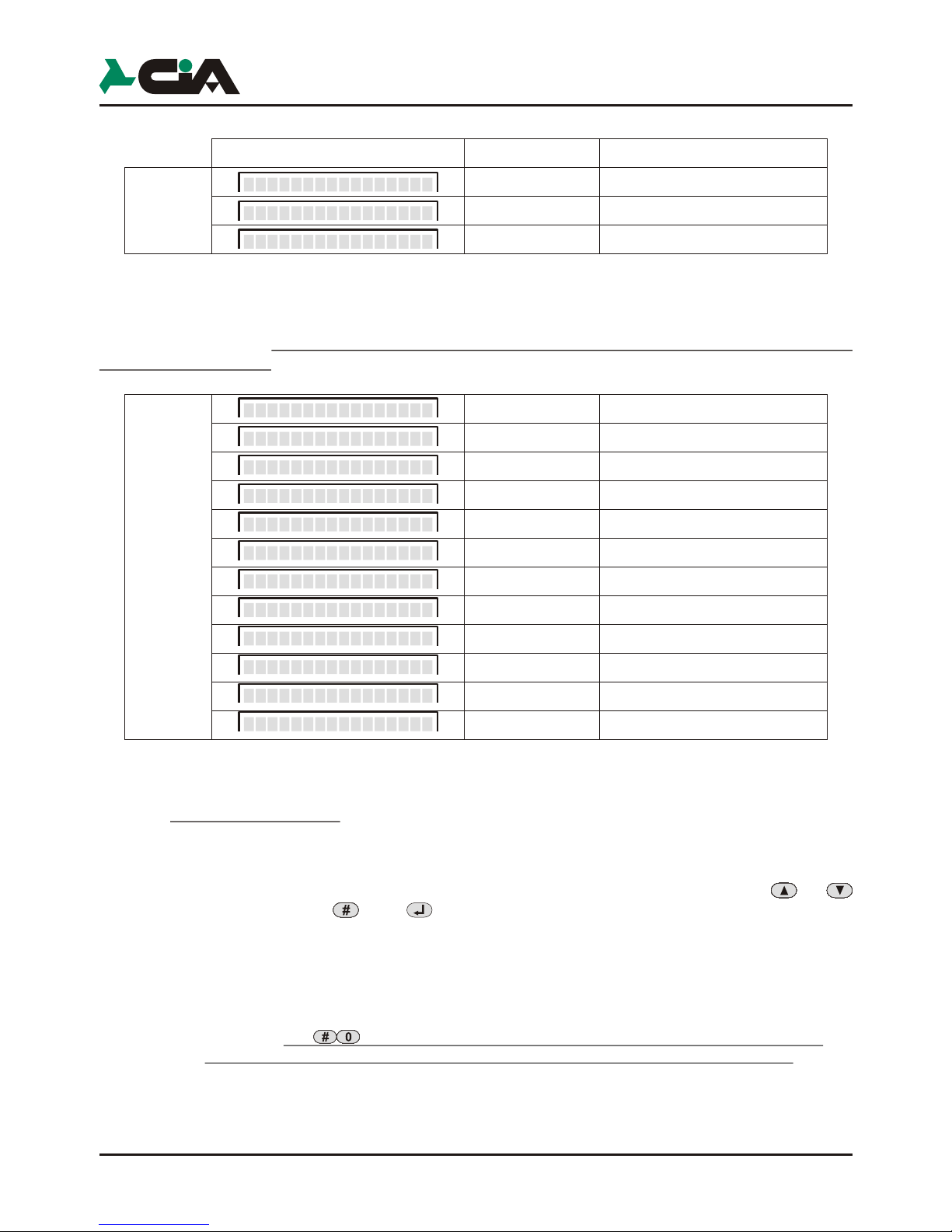
Not active description for channel 1 input
Not presence voltage description for +12V on INT1
Not presence voltage descriptionfor +12V su INT2
Not active description for out 1 output
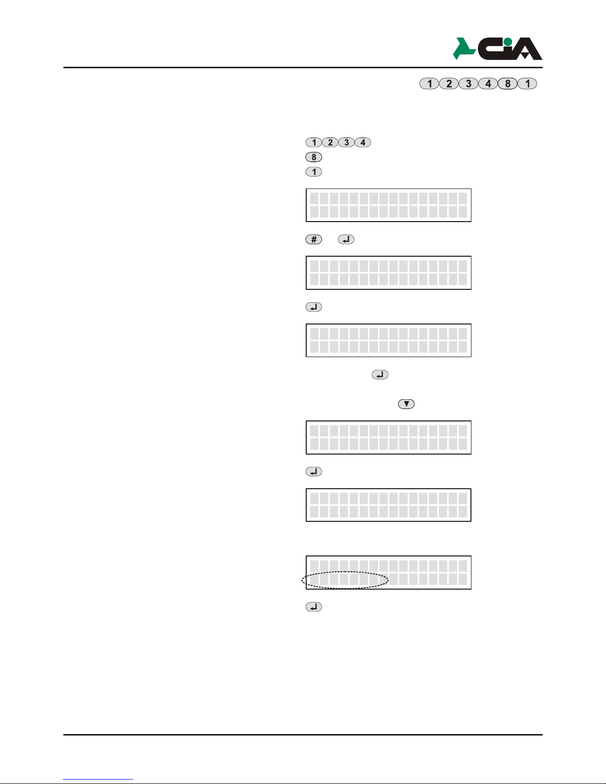
3.4 TXT/SMS messages
In this menu, it is possible to insert or modify the SMS that the combiner it sendes
in alarm case and the descriptions that appear on the display in order to indicate the
state of the input and the outputs.
These descriptions will then be displayed when the interrogation commands or
input and output commands are keyed on the keypad (see para 4.2.3).
!Key in the code: (Default MASTER code)
!Press the button: (Programming)
!Press the button: (SMS Message)
!This will be displayed:
!Press the button: or
!This will be displayed
!Key the SMS message to be stored
For exmaple:
!Press the button:
Once the message to be stored has been keyed in, use the or keys and
then press the or key store the others.
A table of the status of the inputs and outputs which can be visualized in the
upper part of the display:
Channel
Ch.
1
1
Channel
Ch. >
_
1
1
Channel 2
Irrigation >
_
46
Active description for channel 1 input
Not active description for channel 2 input
Active description for channel 2 input
Presence voltage description for +12V on INT1
Presence voltage description for +12V on INT2
Active description for out 1 output
Not active description for out 2 output
Active description for out 2 output
TDC26-TDC36-TM26GSM-TM66GSM-ERMES2- User’s manual
1-Activation
NO
Impulse
1-Activation
NC
Impulse
1-Activation
NO
Level
1-Activation
NC
Level

47
3.5 Channels
In this menu, it is possible to establish how the channels of the combiner must be
activated.
!Key in the code: (Default MASTER code)
!Press the button: (Programming)
!Press the button: (Channels)
!This will be displayed
!Press the button: or
!This will be displayed
!Press the button: or
!This will be displayed
Choose between the activation mode depicted in the table under which condition
the channel is alarmed, using the or keys. Then press the or .
CHANNEL SELECT
Channel 1
_
__
Channel
1-Activation
1
1-Activation
NC
Impulse
The channel is activated from the presence of a
positive 12Vcc to the input of the channel; the cycle
of calls comes started and carried out until the term,
if not interrupted through commandos..
The channel is activated from the absence of a
positive 12Vcc on the input of the channel; the cycle
of calls comes started and carried out until the term,
if not interrupted through commandos
The channel is activated from the presence
of a positive 12Vcc on the input of channel;il the cycle
of calls comes executed until the term if not interrupted
from a command or coming to lack
the positive one on the income
0
12V
Impulse NO
0
12V
Impulse NC
0
12V
Level NO
Level NC
0
12V
The channel is active to lacking the positive one 12Vcc
on the income of thechannel; the cycle of calls comes
activated and carriedout until the term, if not interrupted
through commandos or the restoration of the positive
one 12Vcc on the income
1-Activation
Not Active_
The active channel in no condition and on the first
one display of the combinatore is not come visualized:
Init GSM
Ch1 Disabled
Programmation
In K1 NO
* Play # Rec
_ ________
_ _____ _
In K1 SI
* Play # Rec
_ ________
_ _____ _
In K2 NO
* Play # Rec
_ ________
_ _____ _
In K2 SI
* Play # Rec
_ ________
_ _____ _
INT1 NO
* Play # Rec
_________
_ _____ _
INT1 SI
* Play # Rec
_________
_ _____ _
INT2 NO
* Play # Rec
_________
_ _____ _
INT2 SI
* Play # Rec
_________
_ _____ _
Out 1 NO
* Play # Rec
_ ________
_ _____ _
Out 1 SI
* Play # Re
_ ________
_ _____ _
Out 2 NO
* Play # Rec
_ ________
_ _____ _
Out 2 SI
* Play # Rec
_ ________
_ _____ _
Not active description for channel 1 input
Not presence voltage description for +12V on INT1
Not presence voltage descriptionfor +12V su INT2
Not active description for out 1 output
3.4 TXT/SMS messages
In this menu, it is possible to insert or modify the SMS that the combiner it sendes
in alarm case and the descriptions that appear on the display in order to indicate the
state of the input and the outputs.
These descriptions will then be displayed when the interrogation commands or
input and output commands are keyed on the keypad (see para 4.2.3).
!Key in the code: (Default MASTER code)
!Press the button: (Programming)
!Press the button: (SMS Message)
!This will be displayed:
!Press the button: or
!This will be displayed
!Key the SMS message to be stored
For exmaple:
!Press the button:
Once the message to be stored has been keyed in, use the or keys and
then press the or key store the others.
A table of the status of the inputs and outputs which can be visualized in the
upper part of the display:
Channel
Ch.
1
1
Channel
Ch. >
_
1
1
Channel 2
Irrigation >
_
46
Active description for channel 1 input
Not active description for channel 2 input
Active description for channel 2 input
Presence voltage description for +12V on INT1
Presence voltage description for +12V on INT2
Active description for out 1 output
Not active description for out 2 output
Active description for out 2 output
TDC26-TDC36-TM26GSM-TM66GSM-ERMES2- User’s manual
1-Activation
NO
Impulse
1-Activation
NC
Impulse
1-Activation
NO
Level
1-Activation
NC
Level

49
Key the delay with the keypad (for a maximum of 9999 seconds, equal to 2h 46'
39”) and press the or .
NOTE: If an event which overrides the cycle occurs during the delay period,
the delay timer is restarted, and any new activation will restart the
countdown from the beginning.
3.6 Outputs
In this menu, it is possible to set the function parameters of the outputs, which are:
Mode, Reference Input, and Pulse Duration.
!Key in the code: (Default MASTER code)
!Press the button: (Programming)
!Press the button: (Outputs)
!This will be displayed
Select output (from 1 at 2 for TDC26, TDC36, TM26GSM and to 1 at 6 for
ERMES2, TM66GSM) press the button or .After press the button or
3.6.1 Mode
Once the output has been selected, it is necessary to set its behaviour when it
receives a command of activation or deactivation (see para 4.2.3).
!This will be displayed
!Press the button: or
Use the or to select the “Mode” (see table below). Then press the
Or .
6
OUTPUT SELECTION
Out 1
_
_
Out 1
Mode
_
ON command inverts the state of the output is this result disactive
and have not effect if result activated. In other way the OFF command
invert the output only if this result activated. For estimate the condition
of the output (if is activated or disactivated), the combiner fa reference at the condition
of the output same,or of the input of reference in agreement
to set up how much in the option “Input Refer.” (see par. 3.6.2).
The ON command generates an impulse on the output if this result disactivated
and have not effect if result activated. In other way the command OFF
invert the output only if this result activated.
Also in this modality the state of the escape (active or disactive)
depends from as the parameter for the income of reference
adopts a position. The difference regarding the previous modality consists
that the operation that comes executed is not that
one of the commutation, but is the generation of an impulse off-on-off, of the duration
set up in the parameter "Duration Impulse" (sees par. 3.6.3).
With this choice commandos ON and OFF have always the effect to invert
the state of the escape independently from its condition.
Mode
ON/OFF
Mode
IMPULSE
Mode
TOGGLE
Programmation
48
Once the condition under which the selected channel is alarmed has been
chosen, it is possible to choose whether or not to condition this input to INT1, INT2 or
to In K1, In K2..
“Conditioning” an input means to make it depend on the presence of another
positive to make it operative; in the absence of this condition, the input is inoperative
or, if the condition becomes absent following the activation of the input, it causes the
current cycle to stop.
Example of programming of input IN K1 for cycle activation or burglar alarm
conditioned by the connection of the control panel (+INT):
!NO pulse with +INT active
The cycle of calls starts if the control panel is connected (INT active) and if it
is alarmed (IN K1 activated by the control panel alarm positive).
In this case, to stop the combiner's call cycle, it is sufficient to disconnect
the control panel from the local or remote.
!NO pulse with inactive pulse
In this case, to stop the call cycle, operate the combiner or else wait for the
end of the cycles.
!Press the button
!This will be displayed:
Use the or to select which input (IN1; INT1; IN2; INT2 represented in the
table below) to use as “Input INT”. Then press the or
NOTE: It is not possible to use In K1 as “Input INT” of channel 1 and In K2 as
“Input INT” of channel 2
Once the input on which the function of the interrupted positive input depends has
been indicated for each channel, it is possible to insert a delay between the channel's
activation signal and the actual start of the call cycle
!Press the button
!This will be displayed:
!Press the button or
!This will be displayed:
3-
INT Input
INT1
3-
Delay
0000
3-
Delay
----
Interdetto
Off
Interdetto
In K2_
Interdetto
In K1_
No condition
Input channel 1
Input channel 2
Interdetto
INT2
Interdetto
INT1
Input INT 1
Input INT 2
TDC26-TDC36-TM26GSM-TM66GSM-ERMES2- User’s manual

51
3.7 Parameters
The function parameters of the combiner are set out in this section.
!Key in the code: (Default MASTER code)
!Press the button: (Programming)
!Press the button: (Parameters)
!This will be displayed:
Use the or to select which parameter to use. Then press the or .
NOTE: The functions of the single parameters, and how to reach them directly
from the main menu with a combination of keys, are set out in the
following sub-paragraphs
3.7.1 Remote Control
This parameter is used to enable or disable the combiner to accept remote
control.
NOTE: If this parameter is disabled, the combiner does not respond to calls
coming from outside and does not accept activation or interrogation
commands from the inputs and outputs during the alarm calls.
!Key in the code: (Default MASTER code)
!Press the button: (Programming)
!Press the button: (Parameters)
!Press the button: (Remote control)
!This will be displayed:
Use the or to activate or deactivate this parameter.
3.7.2 Language selection
This menu makes it possible to change the language that the telephone combiner
utilizzed for the indication on dislpay.
!Key in the code: (Default MASTER code)
!Press the button: (Programming)
!Press the button: (Parameters)
!Press the button: (Language)
!Press the button: or
!This will be displayed:
Remote Controls
On
Remote Controls
On
_
Language Choice
English
Programmation
50
3.6.2 Reference input
The reference input is used for the evaluation of the output status (active or
inactive), both for carrying out the commands,for determining the information on the
display or the voice messages to be sent in case of interrogation by the remote.
!Press the botton:
!This will be displayed
Use the or to select which “Input Reference” (see table below) used in
order to determine the state of the escape. Then press the or .
3.6.3 Pulse duration
Set the duration of the pulse generated on the output, expressed in seconds. If
the output is not programmed in pulse mode, this value is ignored.
!Press the button:
!This will be displayed
!Press the button or
!This will be displayed
Select the pulse duration with the keypad, from 1 to 99 seconds.
!Press the button or
Input Reference
INT1
_
Impulse Duration
01
_
Impulse Duration
--
_
Interdetto
In K1
Interdetto
No Input_
Interdetto
Int 2
Interdetto
Int 1
Interdetto
In K2
In this case the output does not make reference to an input, but the state
of assets and disactive is determined from the same condition of the
output: Active OUT1 when the relay of output it connects the clips
Ce NA and OUT2 is active when through the clip can
circular current towards the feeding negative
The output makes reference the INT1 input
The output makes reference the input INT2
The state of the output is determined withreference to the K1 input : with a
present tension of 12V on the K1 inputthe combiner it considers
the active output, while in lack of such tension currency the disattiva output
The output makes reference the K2 input
TDC26-TDC36-TM26GSM-TM66GSM-ERMES2- User’s manual

53
Programmation
52
TDC26-TDC36-TM26GSM-TM66GSM-ERMES2- User’s manual
NOTE: To the first ignition the combiner demands the choice of the language to
use.The available languages are: Italian, English, French, Spanish,
Portuguese, German.
Select the language with or and press or
3.7.3 Reply pulse
Indicates the number of rings the combiner waits for before responding to the call
when remote control is enabled.
!Key in the code: (Default MASTER code)
!Press the button: (Programming)
!Press the button: (Parameters)
!Press the button: (Reply pulse)
!This will be displayed:
!Press the button: or
!This will be displayed:
Select the number of pulses, from 0 to 40 seconds.
NOTE: The combiner don’t accept a number greater than 40 is keyed in. If the
setting '00' is made, the combiner does not respond to external calls.
!Press the button or
3.7.4 Number of calls
This parameter sets how many call attempts the combiner carries out for each
number in the directory in one alarm cycle.
!Key in the code: (Default MASTER code)
!Press the button: (Programming)
!Press the button: (Parameters)
!Press the button: (Number of calls)
!This will be displayed:
!Press the button: oppure
!This will be displayed:
Reply Inpulses
02
_
Reply Inpulses
--
_
No. Of Calls
3
__
No. Of Calls
-
__
Select the number of calls (9 maximum).
Use the or
NOTE: If a “STOP CURRENT CALL” command is sent from the connected telephone
during connection (see para 4.2.7), the call is no longer repeated during the
cycle. With the “STOP CURRENT CYCLE” or “STOP ALL CYCLES”
command, no further calls will be carried out for the current cycle or for all
active cycles.
3.7.5 Number of messages
This parameter indicates how many times the voice messages (common
message + channel message) are repeated at each call.
!Key in the code: (Codice default MASTER)
!Press the button: (Programmazione)
!Press the button: (Parametri)
!Press the button: (Num. Messaggi)
!This will be displayed:
!Press the button: or
!This will be displayed:
Key in the number of voice messages (9 maximum).
!Use the or
NOTE: The call will be interrupted a few seconds following the end of the
messages if the remote control does not intervene.
3.7.6 Beep no registr.
Enabling this parameter, the phone dialer sounds a signal in the absence of GSM
signal
!Key in the code: (Default MASTER code)
!Press the button: (Programming)
!Press the button: (Parameters)
!Press the button: (Beep No registr.)
!This will be displayed:
Use the or to select which parameter to use. Then press the or .
NOTE: By default this parameter is set to OFF.
No. Of Messages
3
__
No. Of Messages
-
__
9
9
Beep No Registr.
On
This manual suits for next models
4
Table of contents
Popular Telephone System manuals by other brands

STARPLUS
STARPLUS Triad XTS user guide

Panasonic
Panasonic KX-TCD445BXS Service manual

Lucent Technologies
Lucent Technologies DEFINITY ProLogix Solutions overview

SpectraLink
SpectraLink Link 150 Installation and operation

Lucent Technologies
Lucent Technologies Octel Unified Messenger Planning guide

ooma
ooma Linx 700-0120-501 quick start guide


