CIAM CIAO Series User guide

ICE CREAM DISPLAY CABINET
CIAO series
Maintenance
And Use Manual
CIAM SPA
Viale dei Pini, 9
Petrignano d'Assisi
PG – Italy
tel. 075 80161
Fax 075 8016 15
http://www.ciamgroup.it
e-mail: info@ciamgroup.it

1. INTRODUCTION
PRESENTATION
Dear Client,
Ciam is pleased to number you among its customers and relies the bought machine will match your expectation. In order to get the best
performances of the machine, we recommend you to follow all suggestions and instructions, which are included in this manual.
1.2. HOW TO USE THE MACHINE
PERMITTED USES
This refrigerated display cabinet has been manufactured for ice cream presentation and sell.
NOT PERMITTED USES
It is absolutely forbidden the use of the refrigerated display cabinet for pharmaceutical products.
1.3. RESPECTED NORMS
The refrigerated display cabinet has been manufactured in respect of the safety issues relevant to the following norm:
Machinery Directive N° 2006/42/CE : CE marking for machinery
Directive N° 2006/95/CE : Low tension
Directive N° 2004/108/CE : Electro-magnetic Compatibility
Directive N° 97/23/EC (P.E.D.) : European Pressure Equipment
Norm CEI 17-13/1 (EN 60439/1) : Realization of Electric Installations
Norm CEI EN 60335-1 (CEI 61-150) : Safety of household and similar electrical appliances
Norm CEI EN 60335-2-24 (CEI 61-56) : Special norms for refrigerators, freezers and ice machines
For ETL marked cabinet:
UL471 / CAN/CSA C22.2 No. 120-M91
NSF/ANSI 7 - 2009
1.4. RESPONSIBILITY
CIAM spa declines any responsibility relevant to damages on persons, animals and/or products in case of:
•No respect of in force norms
•Installation, which is not conform to the instructions manual
•No observance of all maintenance operations, which are suggested in this manual
•No previously agreed change operations with the manufacturer
•
No proper use of the refrigerated display cabinet, for which the machine has been produced.
1.5. WARNING
Anytime CIAM spa reserves the right to up-date the content of this manual and/or to modify the product in order to improve its quality and
performance, without any previous notice and/or communication.
2. DISPLAY CASE DATA PLATE
2.1. DATA PLATE CONTENT
1. Commercial name of the unit
2. Identification number
3. Production date
4. Voltage
5. Phases
6. Frequency
7. Compressor type
8. Number of compressor
9. Refrigerant type
10. Refrigerant weight
11. Climatic rate (Cl.3 = +25°C/60% U.R.; Cl. 4 = +30°C/55% U.R.)
12. Test pressure – system high pressure side
13. Test pressure – system low pressure side
14. Nominal power/current absorbed during defrost
15. Max. power absorbed during defrost
16. Nominal power absorbed by heating elements (only if higher than 100W)
17. Lighting nominal power

3. TECHNICAL FEATURES
CIAO GEL GEL 12 GEL 18 GEL 24
Load limit height
H (mm)
Ice cream pans
5
,
2
dm
3
(
360
x16
5
x1
2
0 mm)
12
18
24
6,5
dm
3
(25
0x
360
x
8
0 mm)
8
12
16
Display ca
binet
weight
(kg)
210
280
320
Display cabinet
performances
Climatic class
-
Environment
(°F/%
R.
H.
)
85 / 55
Working temperature
(°
F
)
0
Electrical supply
(V/ph/Hz)
23
0
/
1
/
50
Refrigeration
Forced air circulation
Dfrosting
Automatic,
by reverse cycle
Refrigera
ting gas
R 404A
Glasses
Heated
side glasses,
hetaed
front glass
Standard internal
compressor
Type
Hermetic single phase
No.
1
1
1
Nominal power
(W)
600
725
2 x 560
Power/current of display cabinet
(W/A)
1800
/
10,0
2
.
05
0/
11,5
2.250/13
,
5
Closing for refrifgerated area
Sliding doors
4. LOAD LIMITS
In the following figure are shown the load limits for the displayed product.
The product should be exposed in order to ensure right air flow ! So it's necessary to comply with the load before
showed.
ATTENTION! The manufacturer is not liable for failures caused by improper use of equipment!

5. INSTALLATION
5.1. MACHINE HANDLING
The ice cream display cabinet handling, from the truck to the final place, has to be made
by any truck-lift, which is proper to its weight. The display cabinet shall be always
balanced in order to ensure personnel integrity and machine functionality
The cabinet can be shipped with or without wood packaging, in case wood crate will be
used, will have a pallet base for an easy fork-lift handling. The pallet, however should be
handle in the central position
During the shipment, it is necessary to avoid any crash or/and shake of the display
cabinet in order to not damage its frame, especially its glasses.
Do not drag the display cabinet on the floor and do not push it on the upper glasses
.
5.2 STOCK OF THE DISPLAY CABINET
Whenever the cabinet has to be stoked, follow carefully what suggested before.
Environmental temperature during the cabinet stock can have following range -15°C and + 55°C and humidity between 30% and 90%.
The display cabinet has always to be protected by sunrays and raining.
In case the display cabinet has to remain in stock quite long time before its use, keep it with its packaging in order to maintain its protection.
5.3. PACKAGING REMOVE
Before getting the display cabinet from the forwarding agent, check its conditions. In case it will be some damages, inform the driver and sign it on
shipping documents. Eventual damages relevant to the shipment and/or to the wrong stock, have not to be ascribed to the manufacturer.
5.4. DISPLAY CABINET POSITION
The refrigerated display cabinet needs particular environmental conditions in order to offer the right performance, so that the area where it will be
used has to respect following indications
Floor has to be l
evelled perfectly, on the contrary keep the display cabinet on the horizontal
position in order to guarantee a perfect defrosting water drain and avoid boring compressor
noises.
The display cabinet has to not be under the
sun
-
rays in order to have its better refrigeration
performance, has to remain inside the local or to be sheltered by window curtain. If what
described above is not observed, it can determinate an increase of temperature of displayed
product and an increasing power consume.
The display cabinet has not to be under air currents due to open doors or windows, or under
roof ventilators or under air condition outlets.
In case will be not respected the above suggestions it can arise an increasing of temperature
of the displayed product and/or an increasing ice phenomena on the evaporator and internal
fans, which compromise the correct cold air circulation and product consistence
The display cabinet has not to be placed close any heat source as heaters, oven
s, etc
The display cabinet has to have a sufficient place in order to ensure a correct custom service,
to make an easy maintenance operation, to guarantee the right air flow necessary to make
cold the condenser. Besides the warm air which flows out has to no have any obstacle or to
invest other equipments in order to not reduce the correct functions.
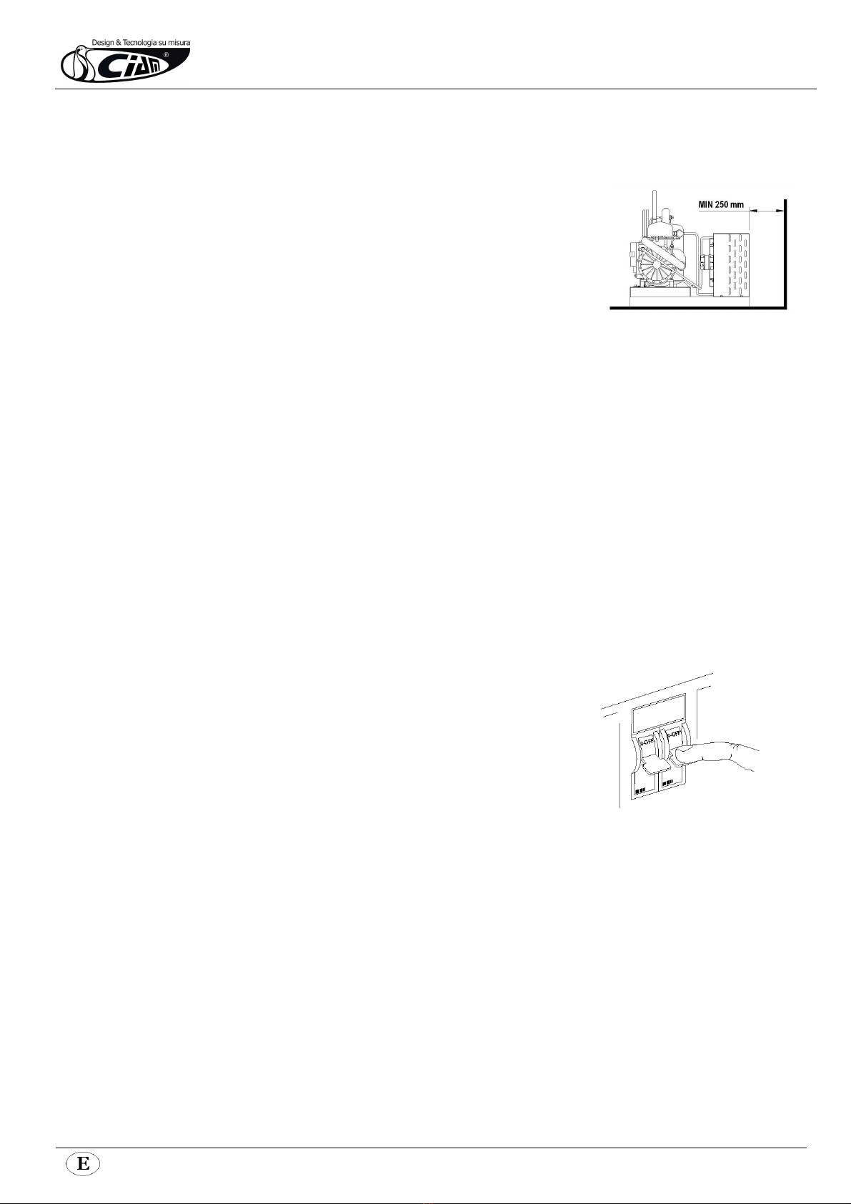
5.5. REMOTE CONDENSING UNIT PLACING
According to the model of ice cream display cabinet you have No.1 or No.2 internal, or remote, condensing units.
The remote condensing unit has to be checked by specialised technicians and according to the required refrigerating power and their position
respect the cabinet. The condensing unit has to be placed following these points:
The condensing unit h
as to be located at least 250 mm from any eventual wall.
(pic.
5
.
1
)
Air flow direction has to be from the eventual wall towards compressor.
The local, in case will be closed, has to be with enough air circulation.
By the condenser has to be guaranteed in any case as much as possible cold air.
In case will be necessary it has to be foreseen a forced air exchange by any fan according to the
air flow of condenser.
The condensing units of display cabinets have to be fixed properly.
The generated noise has not exceed the admitted noise levels relevant to the public places,
especially in case of domestic buildings.
It is always necessary a sufficient place along the four sides of the display cabinet in order to make
easy any type of check and maintenance operations.
When the condensing units are external will be necessary a frame holder that has to be fixed in a
proper way and eventually added with amortising elements. Besides this frame has to be closet with
no-water protection grid and sufficient opening holes for ventilation.
5.6 PIPING CONNECTION BETWEEN DISPLAY CABINET AND REMOTE CONDENSING UNITS.
The liquid and suction piping exit from the base of the display cabine; the choice of piping diameter and insulation thickness has to be taken by
specialised technical personnel, who know specific parameters.
The choice of piping diameter and insulation thickness has to be taken by specialised technical personnel, who know specific parameters.
The piping length has to be as short as possible.
The piping arrangement has to be made on purpose by qualified personnel in order to guarantee the main functionalities as the right inclination,
to have some siphons on the base of suction piping on the way up, and eventually on the intermediate elevation.
WARNING!
A wrong connection may occur serious damages on the display cabinet, especially on the compressor. The display cabinet
manufacturer cannot be responsible of any damage, which can arise from a wrong connection made by third parties.
5.7 ELECTRICAL CONNECTION
Before proceeding with electrical connection, be sure that the available electric power and tension are what is required on technical label of the
cabinet.
The electric connection has to be made by qualified personnel and following manufacturer’s instructions taking into
consideration the relevant norms in force.
The display cabinet has already a general switch, however it is necessary an omni
polar switch, with a minimum distance among the contacts of 3mm.
It is obligatory that the display cabinet will be connected properly with an efficient
ground socket.
WARNING!
A wrong connection may occur always to persons, animals and things,
where the manufacturer cannot be considered as responsible.
WARNING!
The display cabinet has no main switch breaking both the phases.
Before any maintenance operation disconnect the electrical supply of the
display cabinet (see label on the rear of the display cabinet). (pic.5.2).
pic.5.1
pic.5.
2

5.8 – ELECTRICAL CONNECTION – REMOTE CONDENSING UNIT
In case the display cabinet has a remote condensing unit, the electric control panel is supplied separately; in case the display cabinet is without condensing
unit, the machine can be supplied without external control panel. However the electrical connection has to be made in the point indicating in the pic. 5.3.
In this point 5 connecting terminal are not fixed; they are numbered and represent:
1-2 Electrical supply
3-4 Compressor switch
5-6 Defrosting switch
Ground connecting terminal
5.9. IDRAULIC CONNECTION
In case the display cabinet has an internal condensing unit by air, it is not necessary any water system connection.
In case the display cabinet has a dipper well, it is necessary make the connection of its water outlet with the main water drain outlet; besides it is
necessary set a load water tube to the dipper well, to the operator side, to the right or to the left, according to customer’s choice.
In case the display cabinet has condensing unit working fully or partially by water, it is necessary to connect the load water tube (this is the tube with
thermo insulation) with the unload water tube(this is the tube without thermo insulation), of condenser working by water, to the water line
5.10.
IDRAULIC CONNECTION
-
REMOTE CONDENSING UNIT
In the case then display cabinet has a remote condensing unit, it is necessary make the connection of defrosting water outlet with the main water
drain outlet. At the base of cabinet you can find a female pipe-fitting with a rapid receptacle for a tube Ø 32 mm
pic
.
5.3
6. ROUTINE MAINTENANCE AND PERIODIC CHECKS
These kinds of operations are at client’s expenses.
In case some malfunctioning of the unit are observed, please make sure this is not due to non-maintenance reasons, before you apply to qualified
assistance.
The accurate and periodic cleaning of the unit will reduce the risk of damages to the unit itself and to the products stored within.
See following tab for reference.
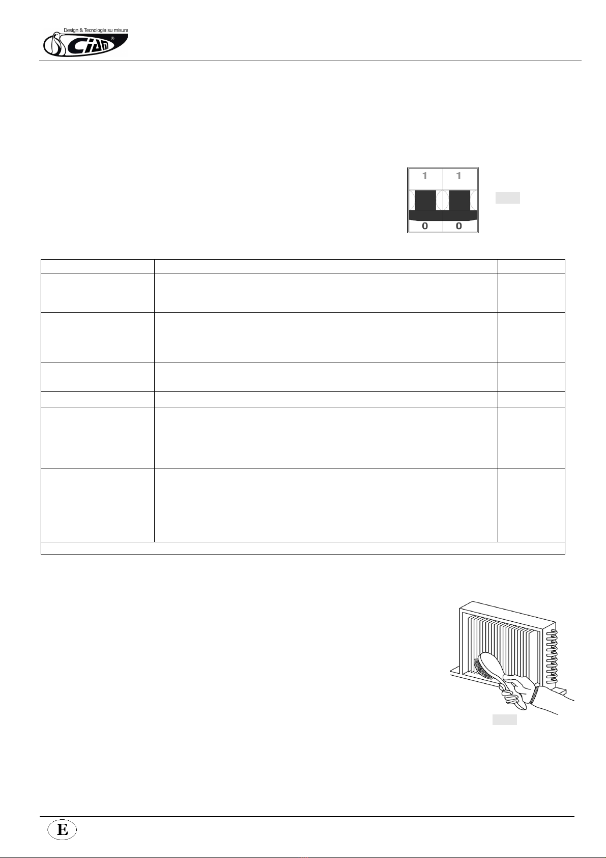
ATTENTION !
Before starting any maintenance and cleaning operation make sure you operate on the
main switch in order to deactivate tension (pic. 6)
(pic 6)
MAINTENANCE OPERATIONS AND THIR FREQUENCY. A SUMMARY TAB.
OPERATION DESCRIPTION FREQUENCY
Surfaces’ cleaning •Wash exclusively with warm water and neutral soup; rinse abundantly and wipe off with a soft
cloth.
•Do not use abrasive products
weekly
Plastic surfaces’ cleaning •Wash exclusively with warm water and neutral soup; rinse abundantly and wipe off with a soft
cloth.
•Do not use alcohol, acetone and any solvent that might spoil the look and structure of the
material.
weekly
Glass surfaces’ cleaning •Use only specific products for glass cleaning
•Using water alone might lead to calcareous deposits on the glass surfaces
daily
Wooden surfaces’ cleaning •Use exclusively a wet cloth. weekly
Additional defrost
•Under particular conditions of temperature and humidity, the frost that normally forms on the
evaporator and fans might increase in volume, so leading to a faulty functioning the unit.
•If these conditions should last, the assistance of a qualified technician shall be needed. Waiting
for this service, it is suggested to operate one or more defrost cycles (despite the damages this
might cause to the stored product)
Waiting for
qualified
assistance
Periodic defrost
•In order to obtain the best performance from the cooling system, we suggest to operate an
extended defrost cycle.
•Before you do that, please remove displayed products from inside the cabinet; always operate
an additional defrost cycle in order to remove from the evaporator the largest possible amount
of frost or ice. Turn the main switch off for 5 hours (min.)
•Before re-starting the unit, make sure that frost has totally melted and wipe carefully.
max. 15 DAYS
ATTENTION! DO NOT CLEA
N THE UNIT WITH WATER JETS
7. EXTRAORDINARY MAINTENANCE
This type of operation has to be made by qualified technician only.
ATTENTION!
Before operating any maintenance, make sure the tension is deactivated. (pic.11).
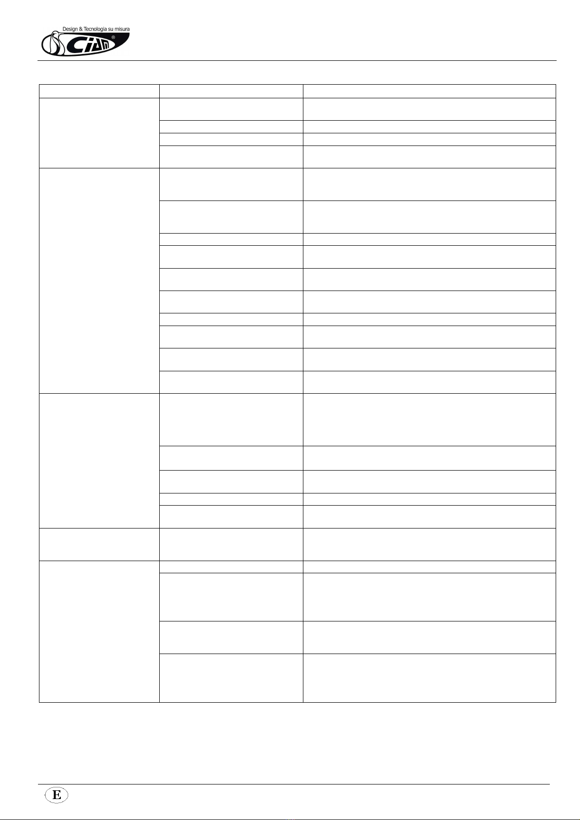
Lamps’ replacement: qualified technician needed.
Air condenser cleaning: qualified technician needed. When the fan is switched off you can clean the condenser
with a compressed air jet. Never use metallic brushes. Use protection gloves (pic.7).
(Pic.7.)
8. DEFECTS AND REMEDIES
DEFECT PROBABLE CAUSES POSSIBLE REMEDIES
The unit does not work Automatic switch released due to
absorption overload
Re-start the automatic switch
Main switch off Turn the main switch on
Refrigeration switch off Turn the refrigeration switch on
Electrical black-out in the building If the black-out does not end in a reasonable time frame, it become
necessary to move the displayed product in another refrigerator
The temperature inside the display
area does not get enough cold
The evaporator(s) is blocked by ice
forming
Operate a complete defrost cycle after having displaced the products in
another refrigerator.Do not put the product back in the cabinet until the real
defect has been identified
The internal fans are damaged or not
working
Replace the damaged fans. If the fans are not damaged, an electrical defect
must be identified. If the fans are replaced, the blades’ inclination have to be
maintained unchanged
Excess of internal ventilation Replace the fans and make sure that blades’ inclination is kept unchanged
The pre-set temperature of the digital
control panel is wrong
Set the correct temperature
The digital control is not working Replace the slave module or the temperature sensor, after you made clear
which one is faulty
The display area is crossed by draught or
exposed to direct/reflected sunbeams
Eliminate draughts and try to avoid sunbeams interference in any way
Air condenser is clogged by dust or dirt Clean the condenser with accuracy
The cooling air flow of the condenser is not
sufficient
Remove everything that might obstacle the air flow through the condenser
Refrigerant gas not sufficient inside the
cooling system
Find and remove the leak inside the system. Refill the system with the
refrigerant
The cooling water flow of the water
condenser is not sufficient
Check that water supply is operating. In case it is, just regulate (or replace)
the regulation valve
The product gets too hard next to
air outlet and too soft next to air
intake
Front evaporator blocked by frost Verify the efficiency of the gasket seal (relatively to the glass superstructure).
Verify that the display area is not crossed by draughts. Verify that backsliders
(or night blind) are always closed, peak hours excepted. Verify that internal
ventilation is sufficient and that the product does not exceed 10mm above
the pans level. Act accordingly
Front evaporator blocked by ice All the a.m. checks are required
Verify, in addition, the defrost cycle efficiency
Back evaporator blocked by ice Verify that the refrigerating and electric systems of the unit are working
properly
Internal fans are not efficient Restore the efficiency of the fans by replacing the damaged ones
The basket seal of the glass
superstructure is not sufficient
Verify the seriousness of the defect and make sure the draughts are
minimized
Some of the products tend to
soften, while some other keep the
right consistence
The temperature inside the display area is
not fit for the products that get too soft
Since the storage temperature cannot be appropriate for any gelato product,
based on different flavours and compositions, it is suggested to display only
similar products together
The compressor does not start or it
does not hold operating
There is no electrical supply Verify there is no black-out in progress. Turn all the power switches on.
The supply tension is too low Verify that nominal tension at connecting clamps is 220V; a tension between
198V and 242V will be acceptable. If the tension does not reach 198V, the
compressor might have problems in starting. Verify the efficiency of electric
installation including the connecting clamps to the compressor
The pre-set temperature on the thermostat
is too high
If the preset temperature is higher than in the display area, the compressor is
not going to work. Change the settings if you verify that the preset
temperature is not enough low
The intervention of the max pressure valve
(where present)
Identify the probable cause among the following:
The air condenser is blocked - The cooling fan of the air condenser is not
working - The room temperature is too high - Lack of cooling water in the
water condenser - The pressure valve is broken - Remove the cause

DEFECT PROBABLE CAUSES POSSIBLE REMEDIES
The compressor works constantly
or for too long periods
The temperature inside the room is too
high
The compressor can only work constantly if there is no chance of decreasing
room temperature (for instance with a.c. system)
The temperature of the compressors’ room
is too high (remote comp.)
See above
The air condenser is blocked Clean the condenser carefully
Cooling air flow of the water condenser is
not sufficient
Check the efficiency of the regulation valve and make sure that taps are
turned on
Lack of refrigerant Identify the eventual leak and refill with refrigerant
Internal ventilation is not sufficient Restore a proper ventilation by replacing the faulty fans or by removing the
eventual obstacle
Evaporators are extremely clogged Operate a complete defrost cycle
The temperature set on the thermostat is
too low
Adjust temperature settings
Temperature is not displayed on
the digital panel
Flat battery Replace battery
Sensor does not work properly Replace digital thermostat
Faulty electronics Replace digital thermostat
Defrost water missing Water drain pipes are blocked Remove the obstacle
Defrost cycle is not efficient Verify the efficiency of control panel (slave module, sensor, solenoid valve..)
and the position of the end cycle sensor
Lighting is not working The switch is off Turn the switch on
The neon lamp is not properly fitted in its
case
Ad just the lamp by rolling it
Exhausted lamp Replace the lamp
Ballasts or starter are not efficient Replace faulty components
The unit is too noisy Vibrations of internal plates Tighten all the fixing screws
Internal fans are not fixed well See above
Fans’ blades are not fixed well Replace faulty fans. If there is friction between the blades and some ice
formation, then act on defrost cycle settings
Pipes are in contact with other parts of
equipment
Avoid any contact between pipes and other parts; a constant rubbing might
wear the pipes out and give way to refrigerant leaking
The unit is not well levelled Adjust the levelling
Condensation water forming on the
glasses
Transformer is not working Check that the transformer is correctly supplied - Verify the correct
functioning of the transformer fuse - Replace the transformer
Heating circuit interrupted Replace the glasses

Leg.Man.Uso Man.ENG-CIAM-13/2012-R02
REFRIGERATION AND ELECTRICAL SYSTEM CABLE CONNECTION GUIDE
AGD
AEL
AP
CA
CAR
CE
CN
CO
D
DEV
DR
EM
EV
F
FD
FLU
FR
HL
I
IEC
IGD
II
IL
IMC
INV
IR
IRP
IV
KM
LF
LI
LIA
LIG
LIP
MDIG
MM
MUC
PA
PD
PO
QE
QF
R
RADD
RE
REL
REP
RES1
RES2
RES3
RES4
RES5
RES6
RES7
RES8
RES9
RES10
RES11
RES12
RES13
RES14
RES15
RES16
RES17
RES18
RES19
RES20
RES21
RES22
RES23
RES24
RES25
RES26
RES27
DIGITAL FLAVOURS DISPLAY FEEDER
ELECTRONIC BALLAST
SERVICE VALVE
SUPPLY CABLE
AIR CONDENSER
ELECTRONIC CONTROL
MULTIPOLAR CONNECTOR
COMPRESSOR
DIOD
SHUNT
REMOTE DISPLAY
PHOTOCELL EMITTER
EVAPORATOR
FUSE
FILTER DRIER
WATER FLOW SWITCH
COMPRESSOR THERMAL PROTECTION
COMPRESSOR ALARM LIGHT
GENERIC SWITCH
WATER EVAPORATION BIN SWITCH
DIGITAL FLAVOURS DISPLAY
LIGHTING SWITCH
SIGHT GLASS
WARM SHELF SWITCH
INVERTER
REFRIGERATION SWITCH
LIGHT REFRIGERATION SWITCH
INTERNAL FAN SWITCH
CONTACTOR
FRONT LIGHTING
INTERNAL UPPER LIGHTING
FRONT LIGHTING
FLAVOURS DISPLAY LIGHTING
REAR LIGHTING
DIGITAL MODULE FOR FLAVOURS DISPLAY
SPINNING SHELVES ELECTRIC MOTOR
CONDENSING UNIT ELECTRIC CONNECTIONS
HIGH PRESSURE CONTROL
HIGH-LOW PRESSURE CONTROL
WATER PUMP
EXTERNAL ELECTRIC PANEL
MAGNETIC-THERMIC SWITCH
LIGHTING BALLAST
RECTIFIER
GENERIC RELAY
ELECTRONIC BALLAST
ELECTRONIC CONTROL TEMPERATURE REPEATER
COLD AIR DISCHARGE HEATING ELEMENT
FRONT PROFILE HEATING ELEMENT
RIGHT/LEFT GLASS HEATING ELEMENT
FRONT GLASS HEATING ELEMENT
DEFROST HEATING ELEMENT
WATER EVAPORATION HATING ELEMENT
TOP LIGHTING FIXTURE HEATING ELEMENT
LATERAL GLASS SUPPORT HEATING ELEMENT
FRONT BAND HEATING ELEMENT
COUPLING BAND HEATING ELEMENT
SERVICE TOP HEATING ELEMENT
UPPER BAND/DOOR FRAME HEATING ELEMENT
HOT DRY/BAIN MARIE DISPLAY HEATING ELEMENT
ANTI-FOG SUCTION AIR BAND HEATING ELEMENT
WARM SHELF HEATING ELEMENT
SIDE BANDS/ FRONT GLASS HINGE HEATING ELEMENT
DEHUMIDIFICATION HEATING ELEMENT
DEFROSTING WATER DRAIN HEATING ELEMENT
RING FRAME HEATING ELEMENT
SIDE BAND HEATING ELEMENT
SUCTION AIR GLASS HEATING ELEMENT
OUTLET AIR HEATING ELEMENT
REAR GLASS HEATING ELEMENT
INTERNAL GLASS HEATING ELEMENT
FRONT GLASS UPPER FRAME HEATING ELEMENT
FRONT GLASS LATERAL/LOWER FRAME HEATING
ELEMENT
FRONT GLASS LATERAL FRAME HEATING ELEMENT
RES28
RES29
RES30
RES31
RES32
RES33
RES34
RES35
RES36
RES37
RES38
REV
REVC
RI
RIC
RICV
RIS
RL
RLA
RO
SAA
SC
SD
SDC
SE
SEC
SFV
SIDG
SL
SLA
SPC
SPMC
SPR
SPS
SS
ST
STR
SU
T
TI
TC
TE
TER
TF
TMC
TP
TRA
TRC
TREV
TS
TVC
V
VC
VEC
VES
VI
VPA
VR
VRA
VRE
VS
VSA
VSAB
VSIC
VSL
VSS
VT
VV
X1
X2
X3
FRONT GLASS LOWER FRAME HEATING ELEMENT
FRONT GLASSES COUPLING PROFILE HEATING ELEMENT
DOORS FRAME MIDDLE POST HEATING ELEMENT
GLASSES PERIMETRAL FRAME HEATING ELEMENT
HEATED DOORS HEATING ELEMENTS
WATER DRAIN HEATING ELEMENT
DOORS FRAME HEATING ELEMENT
COMPRESSOR CRANKCASE HEATING ELEMENT
FRONT GLASS FRAME HEATING ELEMENT
CABINET FRAME HEATING ELEMENT
HOT COMPARTMENT HEATING ELEMENT
CONDENSER FAN SPEED CONTROL
CONDENSER FAN RELAY
REFRIGERANT TAP
COMPRESSOR DELAYER
PHOTOCELL RECEIVER
RESERVE , ANTI-FOG HEATER ELEMENT
LIQUID RECEIVER
WATER LEVEL ELECTRONIC CONTROL
OIL HEATER ELEMENT
ABSENCE OF WATER LIGHT
CONDENSER PROBE
TERMINAL BOX
COMPRESSOR TERMINAL BOX
PROXIMITY SENSOR
MAIN SWITCH
TANK BOTTOM HEATING COIL
FLAVOURS DISPLAY DIGITAL SYSTEM
LIQUID SEPARATOR
WATER LEVER PROBE
COMPRESSOR LIGHT
WARM SHELF LIGHT
ELECTRIC SUPPLY LIGHT
DEFROSTING LIGHT
DEFROSTING PROBE
TEMPERATURE PROBE
LIGHTING STARTER
HUMIDITY PROBE
TEMPERATURE CONTROL
WINTER THERMOSTAT
CAPILLARY TUBE
TIMER
THERMOMETER
FUSIBLE PLUG
WARM SHELF THERMOSTAT
LIGHTING FIXTURES REGRIGERATOR THERMOSTAT
TRANSFORMER
ELECTRONIC CONTROL TRANSFORMER
WATER EVAPORATION HEATER ELEMENT THERMOSTAT
SECURITY THERMOSTAT
CONDENSER FAN THERMOSTAT
COMPRESSOR FAN / GENERAL USE
CONDENSER FAN
WATER EVAPORATION BIN
EXPANSION VALVE
INTERNAL FAN
CONDENSING PRESSURE CONTROL WATER VALVE
CHECK VALVE
SUCTION PRESSURE REGULATION VALVE
EVAPOTATING PRESSURE REGUTATION VALVE
GENERAL USE SOLENOID VALVE
SOLENOID WATER VALVE
BY-PASS SOLENOID WATER VALVE
REVERSING CYCLE SOLENOID VALVE
LIQUID SOLENOID VALVE
DEFROSTING SOLENOID VALVE
POWER REGULATOR
GLASS FAN
CABINET CONNECTIONS
EXTERNAL ELECTRIC PANEL CONNECTIONS
CONDENSING UNIT CONNECTIONS

,QVWDOOLQJDQG2SHUDWLQJ,QVWUXFWLRQV
UHO FRG
UHO FRG
1592009030 XW271 GB_1.doc
;:/ ;:/
1/4
::,1*
;:/ ;:/
;:/ ;:/
1. GENERAL WARNING
1.1 PLEASE READ BEFORE USING THIS MANUAL
• This manual is part of the product and should be kept near the instrument for easy and quick reference.
• The instrument shall not be used for purposes different from those described hereunder. It cannot be
used as a safety device.
• Check the application limits before proceeding.
1.2 SAFETY PRECAUTIONS
• Check the supply voltage is correct before connecting the instrument.
• Do not expose to water or moisture: use the controller only within the operating limits avoiding sudden
temperature changes with high atmospheric humidity to prevent formation of condensation
• Warning: disconnect all electrical connections before any kind of maintenance.
• Fit the probe where it is not accessible by the End User. The instrument must not be opened.
• In case of failure or faulty operation send the instrument back to the distributor or to “Dixell s.r.l.” (see
address) with a detailed description of the fault.
• Consider the maximum current which can be applied to each relay (see Technical Data).
• Ensure that the wires for probes, loads and the power supply are separated and far enough from each
other, without crossing or intertwining.
• In case of applications in industrial environments, the use of mains filters (our mod. FT1) in parallel with
inductive loads could be useful.
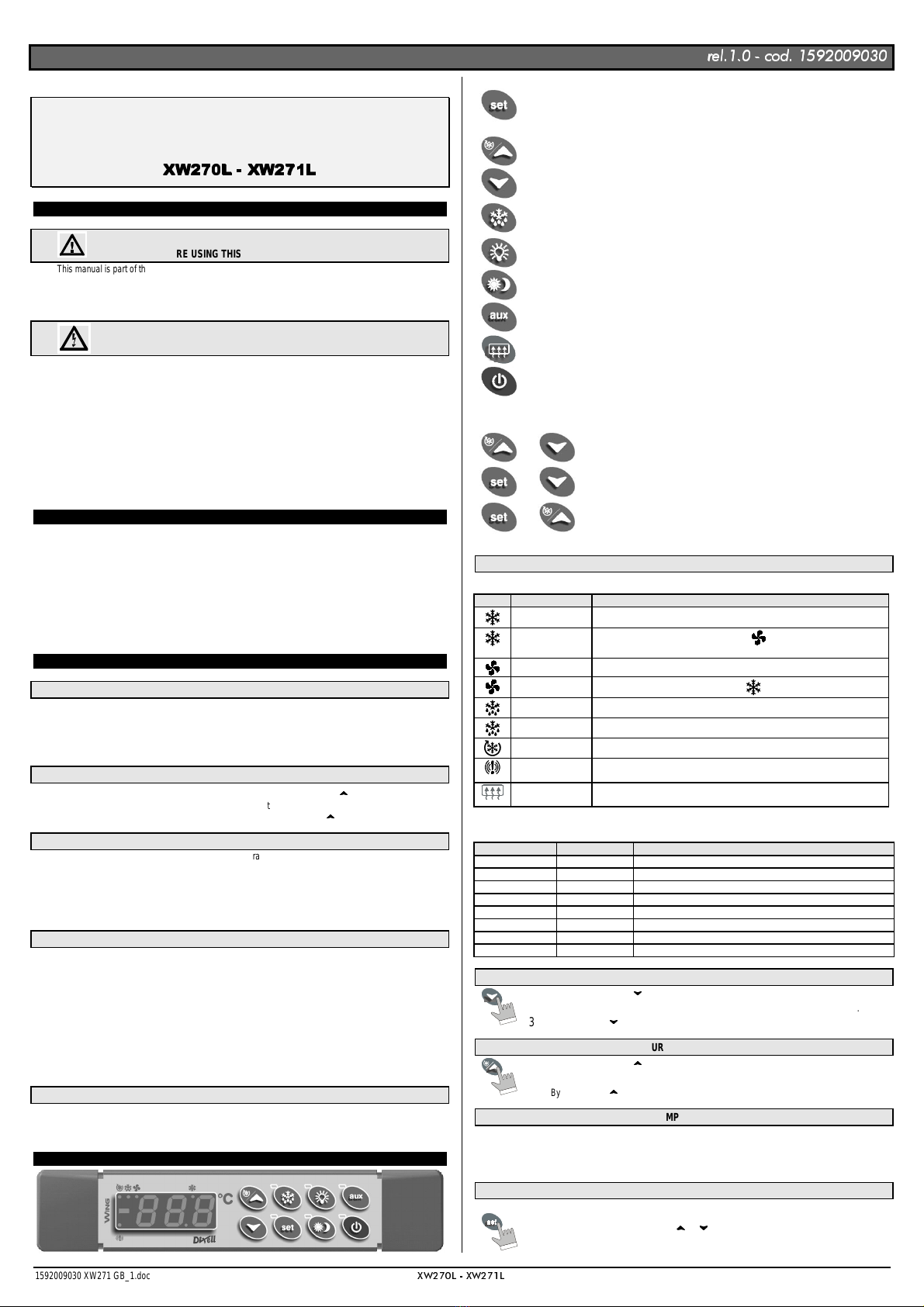
2. GENERAL DESCRIPTION
Models XW270L and XW271L, 38x185 mm format, are microprocessor based controllers suitable for
applications on medium or low temperature refrigerating units. They are provided with six relay outputs to
control compressor, defrost - which can be either electrical or hot gas - the evaporator fans, the lights, the
alarm and an auxiliary output. In XW271L the auxiliary output is configured as anti-condensing heater.
They arealso provided with three NTC probe inputs, one for temperature control,one to control the defrost end
temperature of the evaporator and the third, optional, for the display.There are two digital inputs (free contact)
for the door switch and configurable by parameter.
The standard TTL output allows the user to connect, by means of a TTL/RS485 external module, a ModBUS-
RTU compatible monitoring system and to programme the parameter list with the “Hot Key”.
An optional output for remote display “XW-REP” is available.
3. CONTROLLING LOADS
3.1 THE COMPRESSOR
The regulation is performed according to the temperature measured by the thermostat probe with a positive
differential from the set point: if the temperature increases and reaches set point plus differential the
compressor is started and then turned off when the temperature reaches the set point value again.
In case of fault in the thermostat probe the start and stop of the compressor are timed through parameters
“COn” and “COF”.
3.2 FAST FREEZING
When defrost is not in progress, it can be activated the keypad by holding the
X
X
key pressed for about 3
seconds. The compressor operates in continuous mode for the time set through the “CCt” parameter. The cycle
can be terminated before the end of the set time using the same activation key,
X
X
for about 3 seconds.
3.3 DEFROST
Three defrost modes are available through the “tdF” parameter: defrost with electrical heater, hot gas or
thermostatic defrost. The defrost interval is control by means of parameter “EdF”: (EdF=in) the defrost is made
every “IdF” time, (EdF=Sd) the interval “IdF” is calculate through Smart Defrost algorithm (only when the
compressor is ON and the evaporator temperature is bigger than “SdF” parameter).
At the end of defrost the drip time is controlled through the “Fdt” parameter.
3.4 CONTROL OF EVAPORATOR FANS
The fan control mode is selected by means of the “FnC” parameter:
FnC=C-n fans will switch ON and OFF with the compressor and not run during defrost:;
FnC=C-y fans will run continuously, but not during defrost
After defrost, there is a timed fan delay allowing for drip time, set by means of the “Fnd” parameter.
FnC=O-n fans will switch ON and OFF with the compressor and run during defrost;
FnC=O-y fans will run continuously also during defrost
An additional parameter “FSt” provides the setting of temperature, detected by the evaporator probe, above
which the fans are always OFF. This can be used to make sure circulation of air onlyifhistemperature is lower
than set in “FSt”.
3.5 AUXILIARY OUTPUT
The auxiliary output is switch ON and OFF by means of the corresponding button on the keyboard.
The auxiliary output of the XW271L model controls the anti-condensing heater and it is automatically activated
if the room temperature is lower than the “SAA” parameter.
4. KEYBOARD
To displayandmodifytarget setpoint; in programming mode it selects a parameter or confirm an
operation.
By holding it pressed for 3s when max or min temperature is displayed it will be erased.
To see the max. stored temperature; in programming mode it browses the parameter codes or
increases the displayed value. By holding it pressed for 3s the fast freezing cycle is started.
To see the min stored temperature; in programming mode it browses the parameter codes or
decreases the displayed value.
By holding it pressed for 3s the defrost is started.
Switch ON and OFF the cold room light.
By holding it pressed for 3s Energy Saving function is started or stopped.
For XW270L model. Switch ON and OFF the auxiliary output.
For XW271L model. Switch ON and OFF the anti-condensing heater output.
Switch ON and OFF the instrument.
KEY COMBINATIONS
+ To lock and unlock the keyboard.
+ To enter the programming mode.
+ To exit the programming mode.
4.1 USE OF LEDS
Each LED function is described in the following table.
LED MODE Function
ON The compressor is running
FLASHING - Programming Phase (flashing with LED )
- Anti-short cycle delay enabled
ON The fan is running
FLASHING Programming Phase (flashing with LED )
ON The defrost is enabled
FLASHING Drip time in progress
ON The Fast Freezing cycle is enabled
ON - ALARM signal
- In “Pr2” indicates that the parameter is also present in “Pr1”
ON (Present only in ’XW271L)
The Anti-condensing heater relay (Aux) is ON.
Function of the LEDs placed on the left top side of buttons:
BUTTON MODE FUNCTION
SET FLASHING The Set point is displayed and it can be modified
SET FAST FLASHING The Energy Saving is enabled
DEFROST ON The Manual Defrost is activated
ENERGY SAVING ON The Energy Saving is enabled
LIGHT ON The Light is ON
AUX ON The Auxiliary output is ON (XW270L)
HEATER ON The Anti-condensing heater is ON (XW271L)
ON/OFF ON The instrument is OFF
4.2 HOW TO SEE THE MIN TEMPERATURE
1. Press and release the
W
W
key.
2. The “Lo” message will be displayed followed by the minimum temperature recorded.
3. By pressing the
W
W
key or waiting for 5s the normal display will be restored.
4.3 HOW TO SEE THE MAX TEMPERATURE
1. Press and release the
X
X
key.
2. The “Hi” message will be displayed followed by the maximum temperature recorded.
3. By pressing the
X
X
key or waiting for 5s the normal display will be restored.
4.4 HOW TO RESET THE MAX AND MIN TEMPERATURE RECORDED
To reset the stored temperature, when max or min temperature is displayed :
1. Press SET key until “rST” label starts blinking.
N.B. After the installation RESET the temperature stored .
HOW TO SEE AND MODIFY THE SET POINT
1. Push and immediately release the SET key: the display will show the Set point value;
2. The SET LED start blinking;
3. To change the Set value push the
X
X
or
W
W
arrows within 10s.
4. To memorise the new set point value push the SET key again or wait 10s.
,QVWDOOLQJDQG2SHUDWLQJ,QVWUXFWLRQV
UHO FRG
UHO FRG
1592009030 XW271 GB_1.doc
;:/ ;:/
2/4
TO START A MANUAL DEFROST
1. Push the DEF key for more than 2 seconds and a manual defrost will start.
TO ENTER IN PARAMETERS LIST “PR1”
To enter the parameter list “Pr1” (user accessible parameters) operate as follows:
1. Enter the Programming mode by pressing the Set and DOWN key for few
seconds ( and start blinking).
2. The instrument will show the first parameter present in “Pr1”
TO ENTER IN PARAMETERS LIST “PR2”
To access parameters in “Pr2”:
1. Enter the “Pr1” level.
2. Select “Pr2” parameter and press the “SET” key.
3. The “PAS” flashing message is displayed, shortly followed by “0 - -” with a flashing zero.
4. Use
X
X
or
W
W
to input the security code in the flashing digit; confirm the figure by pressing “SET”. The
security code is “321“.
5. If the security code is correct the access to “Pr2” is enabled by pressing “SET” on the last digit.
Another possibility is the following: after switching ON the instrument the user can push Set and DOWN keys
within 30 seconds.
NOTE: each parameter in“Pr2” can be removed or put into “Pr1” (user level) by pressing “SET” +
W
W
. When a
parameter is present in “Pr1” LED is on.
HOW TO CHANGE THE PARAMETER VALUE
1. Enter the Programming mode.
2. Select the required parameter with
X
X
or
W
W
.
3. Press the “SET” key to display its value ( and LED starts blinking).
4. Use
X
X
or
W
W
to change its value.
5. Press “SET” to store the new value and move to the following parameter.
To exit: Press SET + UP or wait 15s without pressing a key.
NOTE: the new programming is stored even when the procedure is exited by waiting the time-out.
HOW TO LOCK THE KEYBOARD
1. Keep the
X
X
and
W
W
keys pressed together for more than 3 s the
X
X
and
W
W
keys.
2. The “POF” message will be displayed and the keyboard is locked. At this point it is only
possible the viewing of the set point or the MAX o Min temperature stored and to switch
ON and OFF the light, the auxiliary output and the instrument.
TO UNLOCK THE KEYBOARD
Keep the
X
X
and
W
W
keys pressed together for more than 3s.
ON/OFF FUNCTION
By pushing the ON/OFF key, the instrument shows “OFF” for 5 sec. and the ON/OFF LED is
switched ON.
During the OFF status, all the relays are switched OFF and the regulations are stopped; if a
monitoring system is connected, it does not record the instrument data and alarms.
N.B. During the OFF status the Light and AUX buttons are active.
TO SEE THE PROBE VALUES
1. Enter in “Pr2” level.
2. Select “Prd” parameter with
X
X
or
W
W
.
3. Press the “SET” key to display “Pb1” label alternate with Pb1 value.
4. Use
X
X
and
W
W
keys to display the other probe values.
5. Press “SET” to move to the following parameter.
PARAMETER LIST
REGULATION
Hy Differential: (0,1÷25,5°C; 1÷45°F): Intervention differential for set point, always positive. Compressor
Cut IN is Set Point Plus Differential (Hy). Compressor Cut OUT is when the temperature reaches the set
point.
LS Minimum set point limit: (-50,0°C÷SET; -58°F÷SET) Sets the minimum acceptable value for the set
point.
US Maximum set point limit: (SET÷110°C; SET÷230°F) Set the maximum acceptable value for set point.
OdS Outputs activation delay at start up: (0÷255 min) This function is enabled at the initial start up of the
instrument and inhibits any output activation for the period of time set in the parameter. (AUX and Light
can work)
AC Anti-short cycle delay: (0÷30 min) interval between the compressor stop and the following restart.
CCt Thermostat override: (0min ÷23h 50min) allows to set the length of the continuous cycle. Can be used,
for instance, when the room is filled with new products.
Con Compressor ON time with faulty probe: (0÷255 min) time during which the compressor isactive in case
of faulty thermostat probe. With COn=0 compressor is always OFF.
COF Compressor OFF time with faulty probe: (0÷255 min) time during which the compressor is off in case of
faulty thermostat probe. With COF=0 compressor is always active.
DISPLAY
CF Temperature measurement unit: °C = Celsius; °F = Fahrenheit . When the measurement unit is
changed the SET point and the values of the regulation parameters have to be modified
rES Resolution (for °C): (in = 1°C; de = 0,1°C) allows decimal point display.
de = 0,1°C
in = 1 °C
Lod Local display : select which probe is displayed by the instrument:
P1 = Thermostat probe
P2 = Evaporator probe
P3 = auxiliary probe
1r2 = difference between P1 and P2 (P1-P2)
Red Remote display : select which probe is displayed by the remote display (XW-REP)
P1 = Thermostat probe
P2 = Evaporator probe
P3 = auxiliary probe
1r2 = difference between P1 and P2 (P1-P2)
DEFROST
tdF Defrost type:
rE = electrical heater (Compressor OFF)
rT = thermostat defrost. During the defrost time “MdF”, the heater switches On and OFF depending on
the evaporator temperature and “dtE” value.
in = hot gas (Compressor and defrost relays ON)
EdF Defrost mode:
in = interval mode. The defrost starts when the time “Idf” is expired.
Sd = Smartfrost mode. The time IdF (interval between defrosts) is increased only when the compressor
is running(even non consecutively)and only if the evaporator temperature is less than the value in "SdF”
(set point for SMARTFROST).
SdF Set point for SMARTFROST: (-30÷30 °C/ -22÷86 °F) evaporator temperature which allows the IdF
counting (interval between defrosts) in SMARTFROST mode.
dtE Defrost termination temperature: (-50,0÷110,0°C; -58÷230°F) (Enabled only when the evaporator
probe is present) sets the temperature measured by the evaporator probe which causes the end of
defrost.
IdF Interval between defrosts: (1÷120h) Determines the time interval between the beginning of two defrost
cycles.
MdF (Maximum) duration of defrost: (0÷255 min) When P2P = n, no evaporator probe, it sets the defrost
duration, when P2P = y, defrost end based on temperature, it sets the maximum length for defrost.
dFd Display during defrost:
rt = real temperature;
it = temperature reading at the defrost start;
Set = set point;
dEF = “dEF” label;
dEG = “dEG” label;
dAd Defrost display time out: (0÷255 min) Sets the maximum time between the end of defrost and the
restarting of the real room temperature display.
Fdt Drain down time: (0÷60 min.) time interval between reaching defrost termination temperature and the
restoring of the control’s normal operation. This time allows the evaporator to eliminate water drops that
might have formed due to defrost.
dPO First defrost after start-up:
y = Immediately;
n= after the IdF time
dAF Defrost delay after fast freezing: (0min÷23h 50min) after a FastFreezing cycle,the first defrost will be
delayed for this time.
FANS
FnC Fan operating mode:
C-n = running with the compressor, OFF during the defrost;
C-y = running with the compressor, ON during the defrost;
O-n = continuous mode, OFF during the defrost;
O-y = continuous mode, ON during the defrost;
Fnd Fan delay after defrost: (0÷255 min) The time interval between the defrost end and evaporator fans start.
FSt Fan stop temperature: (-50÷110°C; -58÷230°F) setting of temperature, detected by evaporator probe,
above which the fan is always OFF.
ALARMS
ALC Temperature alarm configuration
rE = High and Low alarms related to Set Point
Ab = High and low alarms related to the absolute temperature.
ALU High temperature alarm setting:
ALC= rE, 0 ÷50°C or 90°F
ALC= Ab, ALL ÷110°C or 230°F
when this temperature is reached and after the ALd delay time the HA alarm is enabled.
ALL Low temperature alarm setting:
ALC = rE , 0 ÷50 °C or 90°F
ALC = Ab , - 50°C or -58°F ÷ALU
when this temperature is reached and after the ALd delay time, the LA alarm is enabled,.
AFH Temperature alarm and fan differential: (0,1÷25,5°C; 1÷45°F) Intervention differential for temperature
alarm set point and fan regulation set point, always positive.
ALd Temperature alarm delay: (0÷255 min) time interval between the detection of an alarm condition and
the corresponding alarm signalling.
dAO Delay of temperature alarm at start-up: (0min÷23h 50min) time interval between the detection of the
temperature alarm condition after the instrument power on and the alarm signalling.
EdA Alarm delay at the end of defrost: (0÷255 min) Time interval between the detection of the temperature
alarm condition at the end of defrost and the alarm signalling.
dot Delay of temperature alarm after closing the door : (0÷255 min) Time delay to signal the temperature
alarm condition after closing the door.
doA Open door alarm delay:(0÷255 min) delay between the detection of the open door condition and its
alarm signalling: the flashing message “dA” is displayed.
tbA Buzzer and alarm relay silencing: by pushing one of the keypad buttons.
n= Only the Buzzer is silenced;
y=Buzzer and relay are silenced.
nPS Pressure switch number: (0 ÷15) Number ofactivation of the pressure switch, during the “did” interval,
before signalling the alarm event (I2F= PAL).
PROBE INPUTS
Ot Thermostat probe calibration: (-12.0÷12.0°C/ -21÷21°F) allows to adjust possible offset of the
thermostat probe.
OE Evaporator probe calibration: (-12.0÷12.0°C/ -21÷21°F) allows to adjust possible offsets of the
evaporator probe.
,QVWDOOLQJDQG2SHUDWLQJ,QVWUXFWLRQV
UHO FRG
UHO FRG
1592009030 XW271 GB_1.doc
;:/ ;:/
3/4
O3 Auxiliary probe calibration: (-12.0÷12.0°C/ -21÷21°F) allows to adjust possible offsets of the
evaporator probe.
P2P Evaporator probe presence:
n= not present: the defrost stops only by time; y= present: the defrost stops by temperature and time.
P3P Auxiliary probe presence: n= not present; y= present.
HES Temperature increase during the Energy Saving cycle : (-30,0°C ÷30,0°C / -22÷86°F) sets the
increasing value of the set point during the Energy Saving cycle.
DIGITAL INPUTS
odc Compressor and fan status when open door:
no = normal;
Fan = Fan OFF;
CPr = Compressor OFF;
F_C = Compressor and fan OFF.
I1P Door switch input polarity:
CL : the digital input is activated by closing the contact;
OP : the digital input is activated by opening the contact.
I2P Configurable digital input polarity:
CL : the digital input is activated by closing the contact;
OP : the digital input is activated by opening the contact
I2F Digital input operating mode: configure the digital input function:
EAL = generic alarm;
bAL = serious alarm mode;
PAL = Pressure switch;
dFr = Start defrost;
AUS = Relay AUX actuation;
Es = Energy Saving;
onF = remote On/OFF.
did Time interval/delay for digital input alarm:(0÷255 min.) Time interval to calculate the number of the
pressure switch activation when I2F=PAL. If I2F=EAL or bAL (external alarms), “did” parameter defines
the time delay between the detection and the successive signalling of the alarm.
SAA Set Point for anti-condensing heater: (-50,0÷110,0°C; -58÷230°F) defines the room temperature
setpoint to switch on the anti-condensing heater.
OTHER
Adr RS485 serial address (1÷247): Identifies the instrument address when connected to a ModBUS
compatible monitoring system.
Rel Release software: (read only) Software version of the microprocessor.
Ptb Parameter table: (read only) it shows the original code of the
parameter map.
Prd Probes display: (read only) display the temperature values of the evaporator probe Pb2 and the
auxiliary probe Pb3.
Pr2 Access to the protected parameter list (read only).
DIGITAL INPUTS
The Wing series can support up to 2 free contact digital inputs. One is always configured as door switch, the
second is programmable in seven different configurations by the “I2F” parameter.
DOOR SWITCH INPUT
It signals the door status and the corresponding relay output status through the “odc” parameter:
no = normal (any change);
Fan = Fan OFF;
CPr = Compressor OFF;
F_C = Compressor and fan OFF.
Since the door is opened, after the delay time set through parameter “dOA”, the alarm output is enabled and
the display shows the message “dA”. The alarm stops as soon as the external digital input is disabled again.
During this time and then for the delay “dot” after closing the door, the high and low temperature alarms are
disabled.
CONFIGURABLE INPUT - GENERIC ALARM (EAL)
As soon as the digital input is activated the unit will wait for “did” time delay before signalling the “EAL” alarm
message. The outputs status don’t change. The alarm stops just after the digital input is de-activated.
CONFIGURABLE INPUT - SERIOUS ALARM MODE (BAL)
When the digital input is activated, the unit will wait for “did” delay before signalling the “BAL” alarm message.
The relay outputs are switched OFF. The alarm will stop as soon as the digital input is de-activated.
CONFIGURABLE INPUT - PRESSURE SWITCH (PAL)
If during the interval time set by “did” parameter, the pressure switch has reached the number of activation of
the “nPS” parameter, the “PAL” pressure alarm message will be displayed. The compressor and the regulation
are stopped. When the digital input is ON the compressor is always OFF.
CONFIGURABLE INPUT - START DEFROST (DFR)
It executes a defrost if there are the right conditions. After the defrost is finished, the normal regulation will
restart only if the digital input is disabled otherwise the instrument will wait until the “Mdf” safety time is expired.
CONFIGURABLE INPUT - RELAY AUX ACTUATION (AUS)
This function allows to turn ON and OFF the auxiliary relay by using the digital input as external switch.
CONFIGURABLE INPUT - ENERGY SAVING (ES)
The Energy Saving function allows to change the set point value as the result of the SET+ HES (parameter)
sum. This function is enabled until the digital input is activated.
CONFIGURABLE INPUT - REMOTE ON/OFF (ONF)
This function allows to switch ON and OFF the instrument.
DIGITAL INPUTS POLARITY
The digital inputs polarity depends on “I1P” and “I2P” parameters.
CL : the digital input is activated by closing the contact.
OP : the digital input is activated by opening the contact
INSTALLATION AND MOUNTING
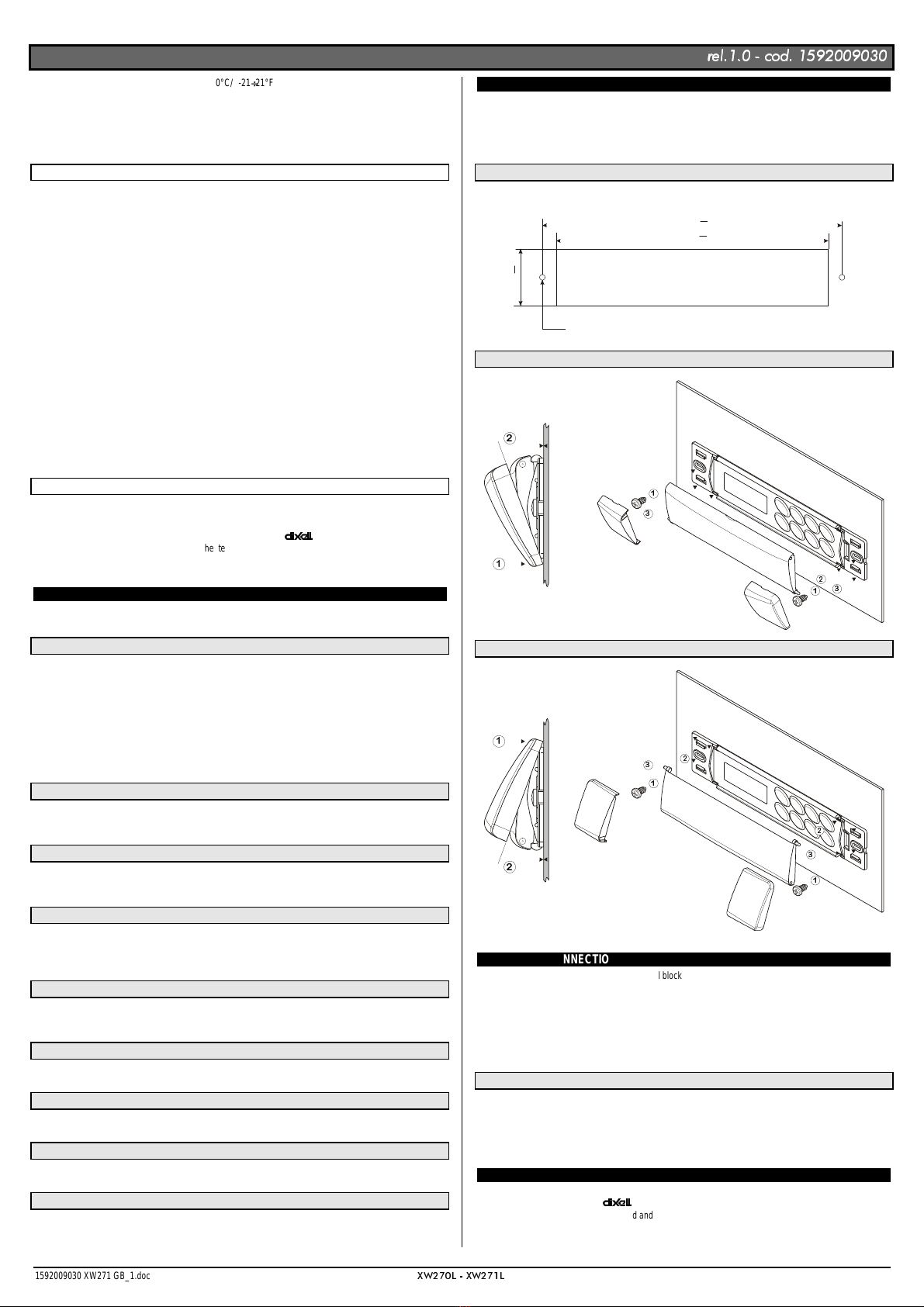
Instruments XW270L, XW271L shall be mounted on vertical panel, in a 150x31 mm hole, and fixed using two
screws ∅3 x 2mm. To obtain an IP65 protection grade use the front panel rubber gasket (mod. RG-L). The
temperature range allowed for correct operation is 0 - 60 °C. Avoid places subject to strong vibrations,
corrosive gases, excessive dirt or humidity. The same recommendations apply to probes. Let the air circulate
by the cooling holes.
CUT OUT
165
150
31
+0.5
-0
+0.5
-0
+1
-1
Ø3 x2
MOUNTING WITH KEYBOARD COVER OPENING DOWNWARD
CLICK!
MOUNTING WITH KEYBOARD COVER OPENING UPWARD
CLICK!
ELECTRICAL CONNECTIONS
The instruments are provided with screw terminal block to connect cables with a cross section up to 2,5 mm2 for
the digital and analogue inputs. Relays and power supply have a Faston connection (6,3mm). Heat-resistant
cables have to be used. Before connecting cables make sure the power supply complies with the instrument’s
requirements. Separate the probe cables from the power supply cables, from the outputs and the power
connections. Do not exceed the maximum current allowed on each relay, in case of heavier loads use a
suitable external relay.
N.B. Maximum current allowed for all the loads is 20A.
PROBE CONNECTIONS
The probes shall be mounted with the bulb upwards to prevent damages due to casual liquid infiltration. It is
recommended to place the thermostat probe away from air streams to correctly measure the average room
temperature. Place the defrost termination probe among the evaporator fins in the coldest place, where most
ice is formed, far from heaters or from the warmest place during defrost, to prevent premature defrost
termination.
TTL SERIAL LINE
The TTL connector allows, by means of the external module TTL/RS485, to connect the unit to a network line
ModBUS-RTU compatible as the
monitoring system XJ500 (Version 3.0).
The same TTL connector is used to upload and download the parameter list of the “HOT KEY“.

,QVWDOOLQJDQG2SHUDWLQJ,QVWUXFWLRQV
UHO FRG
UHO FRG
1592009030 XW271 GB_1.doc
;:/ ;:/
4/4
USE OF THE PROGRAMMING “HOT KEY “
The Wing units can UPLOAD or DOWNLOAD the parameter list from its own E2 internal memory to the “Hot
Key” and vice-versa.
DOWNLOAD (FROM THE “HOT KEY” TO THE INSTRUMENT)
1. Turn OFF the instrument by means of the ON/OFF key, remove the TTL serial cable if present, insert
the “Hot Key” and then turn the Wing ON.
2. Automatically the parameter list of the “Hot Key” is downloaded into the Wing memory, the “DoL”
message is blinking. After 10 seconds the instrument will restart working with the new parameters.
3. Turn OFF the instrument remove the “Hot Key”, plug in the TTL serial cable, then turn it ON again.
At the end of the data transfer phase the instrument displays the following messages:
“end “ for right programming. The instrument starts regularly with the new programming.
“err” for failed programming. In thiscase turn the unit off and then on if you want to restart the download again
or remove the “Hot key” to abort the operation.
UPLOAD (FROM THE INSTRUMENT TO THE “HOT KEY”)
1. Turn OFF the instrumentbymeansofthe ON/OFF key and remove the TTL serial cable if present; then
turn it ON again.
2. When the Wing unit is ON, insert the “Hot key” and push
X
key; the "uPL" message appears.
3. Push “SET” key to start the UPLOAD; the “uPL” message is blinking.
4. Turn OFF the instrument remove the “Hot Key”, plug in the TTL serial cable, then turn it ON again.
At the end of the data transfer phase the instrument displays the following messages:
“end “ for right programming.
“err” for failed programming. In this case push “SET” key if you want to restart the programming again or
remove the not programmed “Hot key”.
ALARM SIGNALS
Message Cause Outputs
“P1” Thermostat probe failure Alarm output ON; Compressor output according to
parameters “COn” and “COF”
“P2” Evaporator probe failure Alarm output ON; Other outputs unchanged
“P3” Auxiliary probe failure Alarm output ON; Other outputs unchanged
“HA” Maximum temperature alarm Alarm output ON; Other outputs unchanged
“LA” Minimum temperature alarm Alarm output ON; Other outputs unchanged
“EE” Data or memory failure Alarm output ON; Other outputs unchanged
“dA” Defrost timeout alarm Alarm output ON; Other outputs unchanged
“dAL” Door switch alarm Alarm output ON; Other outputs unchanged
“EAL” External alarm Alarm output ON; Other outputs unchanged
“BAL” Serious external alarm Alarm output ON; Other outputs OFF
“PAL” Pressure switch alarm Alarm output ON; Other outputs OFF
The alarm message is displayed until the alarm condition is recovery.
All the alarm messages are showed alternating with the room temperature except for the “P1” which is flashing.
To reset the “EE” alarm and restart the normal functioning press any key, the “rSt” message is displayed for
about 3s.
SILENCING BUZZER / ALARM RELAY OUTPUT
If “tbA = y”, once the alarm signal is detected the buzzer and the relay are is silenced by pressing any key.
If “tbA = n”, only the buzzer is silenced while the alarm relay is on until the alarm condition recovers.
“EE” ALARM
The
instruments are provided with an internal check for the data integrity. Alarm “EE” flashes when a
failure in the memory data occurs. In such cases the alarm output is enabled.
ALARM RECOVERY
Probe alarms : “P1” (probe1 faulty), “P2” and “P3”; they automatically stop 10s after the probe restarts normal
operation. Check connections before replacing the probe.
Temperature alarms “HA” and “LA” automatically stopas soon as the thermostat temperature returns to normal
values or when the defrost starts.
Door switch alarm “dA” stop as soon as the door is closed.
External alarms “EAL”,“BAL” stop as soon asthe external digital input isdisabled “PAL” alarm is recovered by
switching OFF the instrument.
TECHNICAL DATA
Housing: self extinguishing ABS.
Case: facia 38x185 mm; depth 76mm
Mounting : panel mounting in a 150x31 mm panel cut-out with two screws. ∅3 x 2mm.
Distance between the holes 165mm
Protection: IP20.
Frontal protection: IP65 with frontal gasket mod RG-L. (optional)
Connections: Screw terminal block ≤2,5 mm2heat-resistant wiring and 6,3mm Faston
Power supply: 230Vac or. 110Vac ±10%
Power absorption: 7VA max.
Display: 3 digits, red LED, 14,2 mm high.
Inputs: 3 NTC probes
Digital inputs: 2 free voltage
Relay outputs: Total current on loads MAX. 20A
compressor: relay SPST 20(8) A, 250Vac
light: relay SPST 16(3) A, 250Vac
fans: relay SPST 8(3) A, 250Vac
defrost: relay SPST 8(3) A, 250Vac
alarm: SPST relay 8(3) A, 250Vac
auxiliary: SPST relay 16(3) A, 250Vac
Other output : alarm buzzer
Serial output : TTL standard
Communication protocol: Modbus - RTU
Data storing: on the non-volatile memory (EEPROM).
Kind of action: 1B.
Pollution grade: normal
Software class: A.
Operating temperature: 0÷60 °C.
Storage temperature: -25÷60 °C.
Relative humidity: 20÷85% (no condensing)
Measuring and regulation range: NTC probe: -40÷110°C (-58÷230°F)
Resolution: 0,1 °C or 1°C or 1 °F (selectable).
Accuracy (ambient temp. 25°C): ±0,5 °C ±1 digit
CONNECTIONS
XW270L/XW271L
(*) In XW271L, AUX is an anticondensing heater
Common
Door switch
Digital inp.
Def.
Display
Room
;:/;:/
ALARM
AUX
(*) Def. Comp
Fan Light
Line
Neutral
20A
250Vac MAX
20A
8A
250Vac 16A
250Vac
8A
250Vac 8A
250Vac
16A
250Vac
DEFAULT SETTING VALUES
Label Name Range Default Level
REGULATION °C/°F XW270L XW271L
Set Set point LS÷US -5 Pr1 Pr1
Hy Differential 0,1÷25,5 °C / 1÷45°F 2 Pr1 Pr1
LS Minimum set point -50,0°C÷SET / -58°F÷SET -30 Pr2 Pr2
US Maximum set point SET ÷ 110°C / SET ÷ 230°F 20 Pr2 Pr2
OdS Outputs activation delay at start up 0÷255 min. 1 Pr2 Pr2
AC Anti-short cycle delay 0÷30 min. 1 Pr1 Pr1
CCt Compressor ON time during fast
freezing 0 ÷ 23h 50 min. 0 Pr2 Pr2
COn Compressor ON time with faulty probe 0÷255 min. 15 Pr2 Pr2
COF Compressor OFF time with faulty probe 0÷255 min. 30 Pr2 Pr2
DISPLAY
CF Temperature measurement unit °C ÷ °F °C Pr2 Pr2
rES Resolution (integer/decimal point) in ÷ de de Pr1 Pr1
Lod Local display P1 ÷ 1r2 P1 Pr2 Pr2
Red Remote display P1 ÷ 1r2 P1 Pr2 Pr2
DEFROST
tdF Defrost type rE, rT, in rE Pr1 Pr1
EdF Defrost mode In, Sd In Pr2 Pr2
SdF Set point for SMART DEFROST -30 ÷ +30°C / -22÷+86°F 0 Pr2 Pr2
dtE Defrost termination temperature
(1°Evaporator) -50,0÷110°C/ -58÷230°F 8 Pr1 Pr1
IdF Interval between defrost cycles 1÷120h 6 Pr1 Pr1
MdF (Maximum) length for 1° defrost 0÷255 min. 30 Pr1 Pr1
dFd Displaying during defrost rt, it, SEt, dEF, dEG it Pr2 Pr2
dAd MAX display delay after defrost 0÷255 min. 30 Pr2 Pr2
Fdt Draining time 0÷60 min. 0 Pr2 Pr2
dPO First defrost after start up n ÷ y n Pr2 Pr2
dAF Defrost delay after fast freezing 0 ÷ 23h 50 min. 2 Pr2 Pr2
FANS
FnC Fans operating mode C-n, C-y, O-n, O-y O-n Pr2 Pr2
Fnd Fans delay after defrost 0÷255 min. 10 Pr2 Pr2
FSt Fans stop temperature -50,0÷110°C/ -58÷230°F 2 Pr2 Pr2
ALARMS
ALC Temperature alarms configuration rE÷Ab rE Pr2 Pr2
ALU MAXIMUM temperature alarm -50,0÷110°C/ -58÷230°F 10 Pr1 Pr1
ALL minimum temperature alarm -50,0÷110°C/ -58÷230°F 10 Pr1 Pr1
AFH Temperature alarm and fan differential 0,1÷25,5 °C / 1÷45°F 2
ALd Temperature alarm delay 0÷255 min. 15 Pr2 Pr2
dAO Delay of temperature alarm at start up 0 ÷ 23h 50 min. 1,3 Pr2 Pr2
EdA Alarm delay at the end of defrost 0÷255 min. 30 Pr2 Pr2
dot Delay of temperature alarm after closing
the door 0÷255 min. 15 Pr2 Pr2
dOA Open door alarm delay 0÷255 min. 15 Pr2 Pr2
tBA Alarm relay silencing y ÷ n y Pr2 Pr2
nPS Pressure switch activation number 0÷15 0 Pr2 Pr2
ANALOGUE INPUTS
Ot Thermostat probe calibration -12,0÷12,0°C / -21÷21°F 0 Pr1 Pr1
OE Evaporator probe calibration -12,0÷12,0°C / -21÷21°F 0 Pr2 Pr2
O3 Auxiliary probe calibration -12,0÷12,0°C / -21÷21°F 0 Pr2 Pr2
P2P Evaporator probe presence n ÷ y y Pr2 Pr2
P3P Auxiliary probe presence n ÷ y n Pr2 Pr2
HES Temperature increase during the Energy
Saving cycle -30÷30°C / -22÷86°F 0 Pr2 Pr2
DIGITAL INPUTS
Odc Open door control no, Fan, CPr, F_C Fan Pr2 Pr2
I1P Door switch polarity CL÷OP CL Pr2 Pr2
I2P Configurable digital input polarity CL÷OP CL Pr2 Pr2
i2F Digital input configuration EAL, bAL, PAL, dFr,
AUS, ES, OnF EAL Pr2 Pr2
dId Digital input alarm delay 0÷255 min. 5 Pr2 Pr2
SAA Set point for anti-condensing heater -50,0÷110°C/ -58÷230°F -20.0 - - - Pr2
OTHER
Adr Serial address 0÷247 1 Pr1 Pr1
rEL Software release - - - 1.0 Pr2 Pr2
Ptb Map code - - - - - - Pr2 Pr2
Prd Probes display Pb1÷Pb3 - - - Pr2 Pr2
Pr2 Access parameter list - - - - - - Pr2 Pr2
Dixell s.r.l. Via dell’Industria, 27 - 32010 Z.I Pieve d’Alpago (BL) ITALY
tel. +39 - 0437 - 98 33 - fax +39 - 0437 - 98 93 13 -
(PDLOGL[HOO#GL[HOOFRP KWWSZZZGL[HOOFRP
This manual suits for next models
3
Table of contents
Popular Merchandiser manuals by other brands

Hussmann
Hussmann Impact Excel C2X-LGEP Technical data sheet

Hussmann
Hussmann RI2-E Technical data sheet

Hussmann
Hussmann RI3-N Technical data sheet

Hussmann
Hussmann Impact C2-XLE Technical data sheet

Alto-Shaam
Alto-Shaam ITM2-48/STD Installation & operation instruction

Goldmedal
Goldmedal Sterno Pretzel Warmer instruction manual


