Cipax CPX Series User manual


2
Allmänt
CPX sluten tank 1350 L, art nr 23013, är rotationsgjuten i slagtålig och åldersbeständig
polyetenplast avsedd att användas för:
-Dricksvatten.
-Regnvatten.
-Avloppsvatten.
-Andra vätskor, dock ej brandfarliga!
Tanken är tillverkad i ett FC-godkänt material. (FC=Food Contact)
Kontakta leverantören för ytterligare information.
Tanken är ej avsedd att användas som slamavskiljare.
RISE (Research Institutes of Sweden, Fd. SP, Sveriges Tekniska Forskningsinstitut) har
godkänt hållfasthetsberäkningen utförd enligt EN-12566-1.
Tanken levereras som standard med låsbart lock, även det rotationsgjutet i polyetenplast.
Locket är testat och godkänt av SP enligt Boverkets handbok om ”Barnsäkra brunnar” och SP
metod 0487 genomtrampningsprov utgåva 3.
Installation av tanken kan ske både ovan och under jord. Dock krävs det att tanken får stöd
vid installation ovan jord. Se vidare instruktion.
Garanti
Installation och användarbeskrivning måste följas.
Om tank och övriga komponenter utsatts för oaktsam behandling eller om installation och
användarbeskrivning ej följts kan garantin upphöra att gälla.
Säkerhet
Lockets lås skall öppnas och stängas med
verktyg, t.ex. hylsverktyg.
Låset ska alltid vara i stängt läge när locket ligger på tanken!
Varning!
Gå aldrig ner i avloppstank som satts i bruk.
Gaserna kan innebära medvetslöshet och
direkt livsfara.
3
Tillbehör
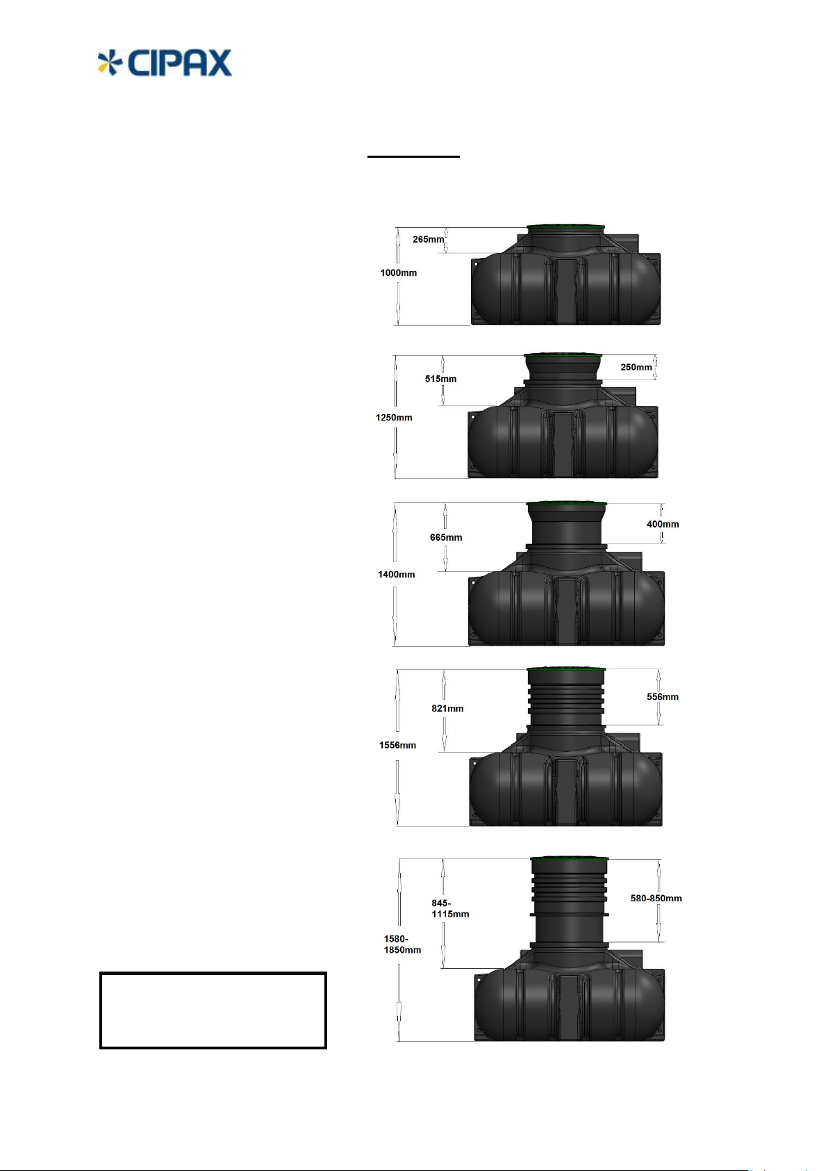
Standard Standardutförande utan extra hals
För installation under jord så finns fyra
olika förhöjningshalsar för att nå önskat
nedgrävningsdjup. Tanken har som
standard en inbyggd hals med höjd
265 mm.
_______________________________________________________________________
Förhöjningshals, CPX art nr: 450251
Fast hals höjd 250 mm.
_______________________________________________________________________
Förhöjningshals, CPX art nr: 450501
Fast hals höjd 400 mm.
_______________________________________________________________________
Förhöjningshals, CPX art nr: 450121
Fast hals höjd 556 mm.
_______________________________________________________________________
Teleskophals, CPX art nr: 450141
Justerbar teleskophals mellan
580-850 mm. Denna hals följer även
rörelser i marken.
Samtliga halsar levereras
med monteringssats.
CPX art nr: 45029
4
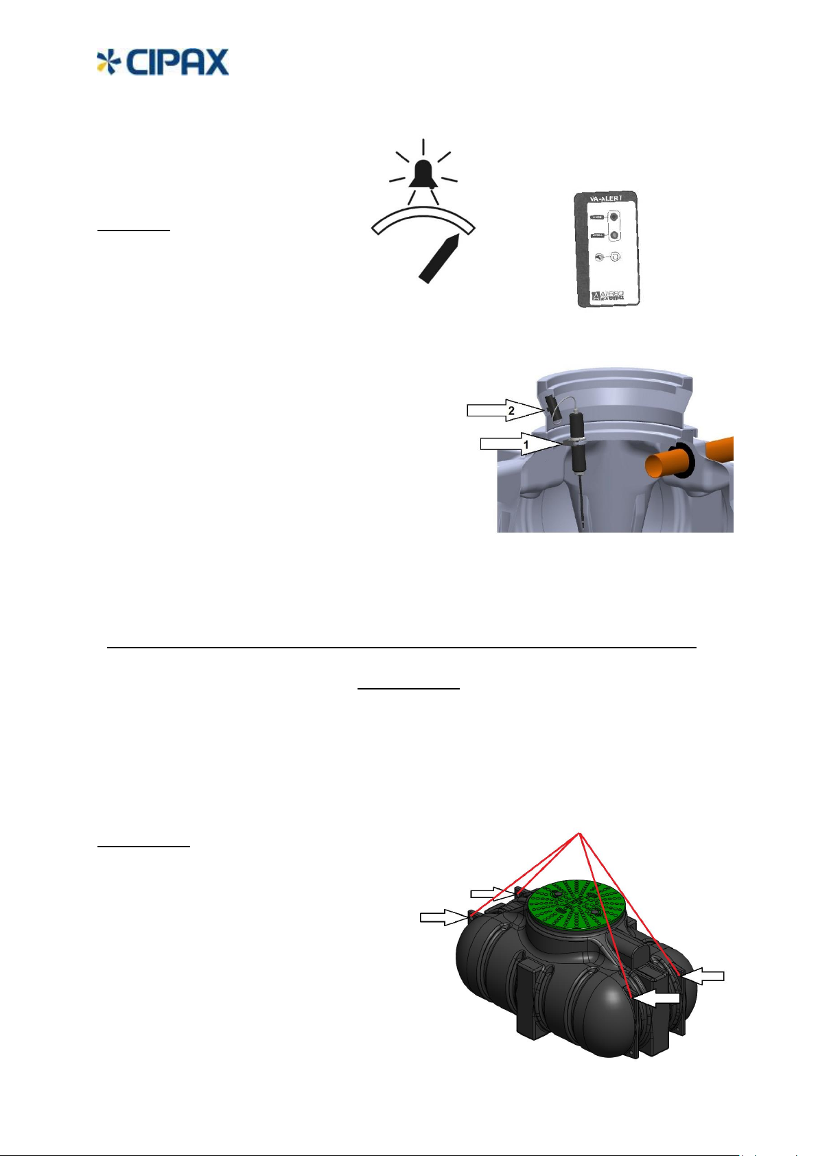
Nivålarm
Cipax art nr:
606171, 10 m kabel
606181, Trådlöst med batterier.
Nivågivaren (1) monteras på kanten i tanken enl bild
med medföljande skruv, bricka och mutter.
Ett 8 mm monteringshål borras först ca 90 grader
mot inkommande avloppsrör.
Larmet aktiveras när ca 300 L återstår. Om så önskas
kan slangklämman flyttas från inställd placering på
röret för att aktivera larmet tidigare eller senare.
För artikel 606181 placeras den trådlösa sändaren på
högsta lämpliga höjd och fästs med medföljande skruv.
För artikel 606171 borras ett 16 mm hål för kabelgenomföringen. Grada hålet! Med en syl el
liknande görs ett hål i kabelgenomföringen och kabeln kan träs igenom.
Hantering
Tank, utrustning och tillbehör ska hanteras varsamt. Låt inga föremål som kan skada dessa
komma i närheten. Vid mottagande samt innan installation, inspektera produkterna
noggrant med avseende på eventuella skador.
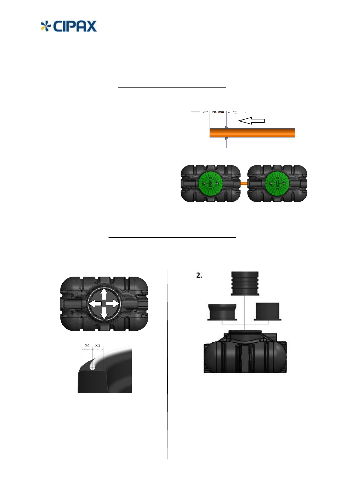
Lyft av tank
Tanken får endast lyftas med mjuka band som
kan träs genom de fyra inbyggda lyftöglorna
Tanken blir då välbalanserad vid lyft.
Endast tom tank får lyftas.

5
Installation under jord
Välj en plats där marken bedöms som väldränerad och fast. Vid risk för inträngning av
grundvatten i gropen så är det till fördel om en dränering ut från gropen ordnas. Minsta
storlek på gropen bör vara minst ca 50 cm runt om tankens yttermått.
Tanken får inte ligga där det finns risk för överkörning av t.ex. personbil eller där
grundvattennivån hela eller delar av året riskerar att nå upp till inloppsröret eller där marken
är sank och lös. Hänsyn bör även tas till vilket tjäldjup som råder på platsen.
Installation ovan jord
Då tanken är konstruerad för att ha jordstöd runt om så måste detta simuleras vid
installation ovan jord. Till exempel mha en stödram. Kontakta CIPAX för mer info.
Förankring av tank
Om minsta risk finns för att grundvatten kan nå upp
till tanken bör tanken förankras.
Om band används så bör dessa vara ålderbeständiga.
Dessa band placeras lämpligast enligt skissen
till hö. Se till att inga vassa kanter på bandlåsen ligger
mot tanken. Alternativt kan sk. förankringduk
användas.
När förankringsband används så ska ankarplattor
av tillräcklig vikt och storlek förankras för
att förhindra att tanken kan flyta upp.
Tanken bör stå på en minst 150 mm tjock
avplanad och väldränerad grus eller sandbädd
utan vassa stenar som kan skada tanken.
Komprimera gärna bädden med maskin.
Tänk på att:
Lyftkraften vid tom tank och
max tillåten grundvattennivå är 13500 N
6
eller motsvarande 1350 kg!
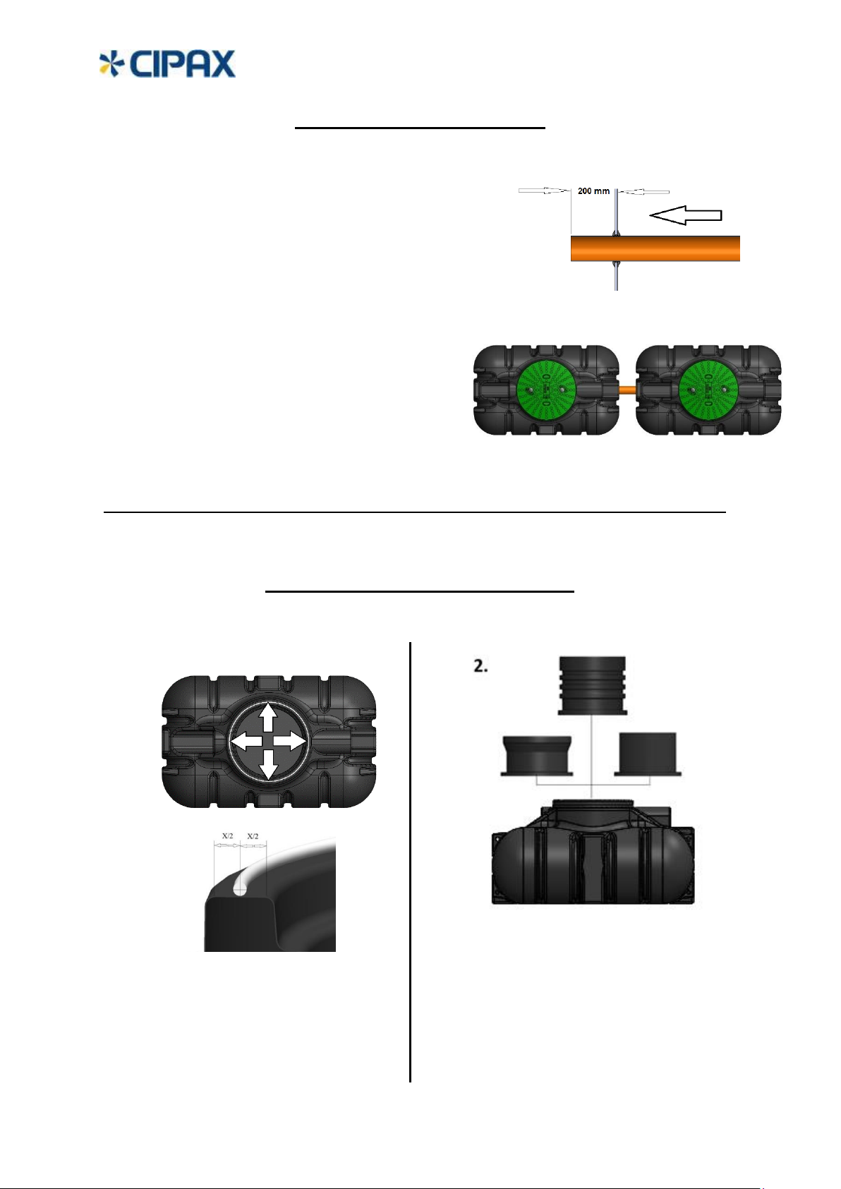
Förberedelse installation
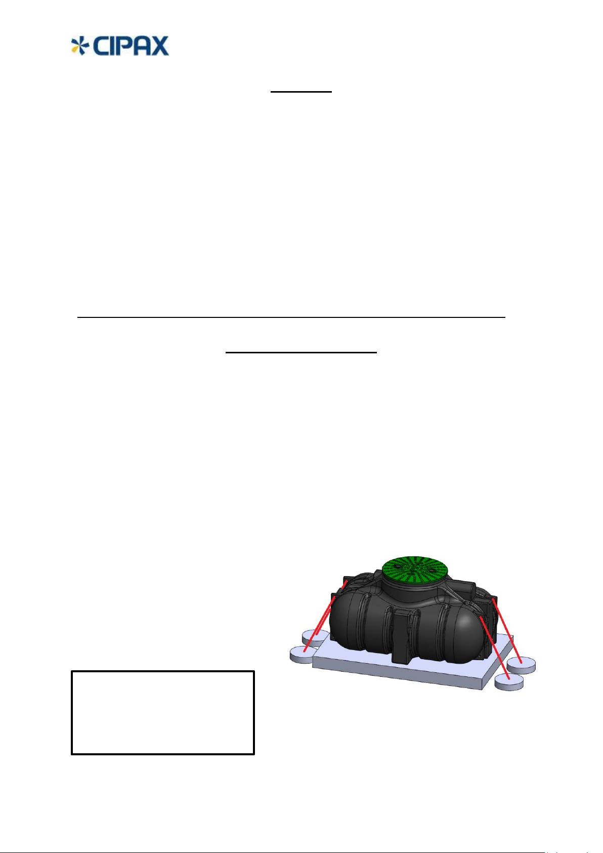
Inloppsrör bör skjutas in ca 200 mm in i tanken.
Inloppsmuff för Ø 110 mm finns att tillgå från
CPX art nr: 67502
Seriekoppling av tankar
Röret kan anslutas både på kortsidorna
och långsidorna som har anslutningsplan
på samma höjder. Tankarna bör ha ett avstånd
på minst 500 mm för att säkerställa återfyllning,
om tankarna är nedgrävda.
Montering av förhöjningshals
Samtliga förhöjningshalsar monteras på tanken på identiskt sätt.
1.
Gör ren anläggningsytan på tanken
och lägg en flödig sträng av
medföljande tätmedel/fästmassa
runt tankens hals mitt på ytan.
Gör ren anläggningsytan på
förhöjningshalsen, centrera noga
och ställ ner på tanken. Undvik
att flytta förhöjningshalsen i
sidled när den väl står på tanken!

7
3.
_______________________________________________________________
Återfyllning
Packa återfyllnadsmaterial, grus eller sand utan vassa
stenar som kan skada tanken, närmast tanken och
minst 200 mm runt om. Se noga till att fylla ut och
packa runt nederkanten så tanken får bra stadga.
Använd EJ markvibrator vid återfyllning!
_______________________________________________________________
Tömning av tank
Normalt ska tömning ske genom
locket men om tömning önskas ske genom
separat tömningsrör, som då bör rekommenderas
av ortens slamtömmare, måste ett
ventilationsrör monteras. Ventilationsröret bör ha
en diameter 1,5 x diametern på tömningsröret.
Utan ventilationsrör riskerar tanken
att sugas ihop vid tömning.
Skruva fast förhöjningshalsen
med de medföljande
skruvarna. Dra skruvarna
försiktigt växelvis tills dess att
förhöjningshalsen bedöms
ha bottnat mot tanken.

8
Tekniska data
Se sista sidan för ritning på tanken!
-Volym: 1350 L
-Vikt: 85 kg, inklusive lock
-Tillåtet installationsdjup, max 2000 mm
-Tillåten grundvattennivå, max 675 mm
från tankens botten.
-Tillåten belastning på lock och sarg
max 250 kg.

9
General
The CPX 1350 L closed tank, Part No. 23013, is rotationally moulded in impact resistant and
durable polythene plastic to be used for:
-Drinking water.
-Rainwater.
-Wastewater.
-Other liquids. No flammable!
The tank is manufactured using an FC-approved material. (FC=Food Contact). Contact the
supplier for further information.
The tank is not intended for use as a septic tank.
RISE (Research Institutes of Sweden, former SP, Technical Research Institute of Sweden) has
performed strength testing, granting approval in accordance with EN-12566-1.
The tank is supplied as standard with a lockable cover, which is also produced from rotationally
molded polyethylene plastic. The cover has been tested and approved by SP in accordance with
the Swedish National Board of Housing's handbook for "Childproof wells" and SP method 0487
Trample Test version 3.
The tank can be installed above and below ground. When the tank is installed above ground the
tank will need additional support. See further instruction.
Warranty
The installation and user instructions must be followed.
If the tank and its other components are subjected to negligent treatment or if the installation
and user instructions are not followed, this may void the warranty.
Safety
The cover must be locked and unlocked using
the correct tools, e.g. a socket tool.
The cover must always be locked when placed on the tank.
Warning!
Never enter a wastewater tank that is in use.
The gases may lead to unconsciousness
and pose a life-threatening hazard.

10
Acessories
Standard design without optional neck
Standard
For underground installation there are four
different neck extensions to achieve the
required burial depth. As standard, the
tank has a built-in neck for a burial
depth of 265 mm.
_______________________________________________________________________
Extension neck, CPX Part No. 450251
Extension neck height 250 mm.
_______________________________________________________________________
Extension neck, CPX Part No. 450501
Extension neck height 400 mm.
______________________________________________________________________
Extension neck, CPX Part No. 450121
Extension neck height 556 mm.
_______________________________________________________________________
Telescopic neck, CPX Part No. 450141
Adjustable telescopic neck. Height
between 580-850 mm. This neck also
follows ground movements.
All extension necks are supplied
with assembly kit
CPX Part No. 45029

11
Level Alarm
CPX Part No.
606171, 10 m cable
606181, Wireless with batteries.
Mount the level sensor (1) with supplied M8
screw, washer and nut at the edge of the tank as shown in
the picture. First drill an 8 mm hole approximately 90
degrees away from the Inlet pipe.
The alarm will be triggered when fluid reaches both contact
surfaces located in the far end of the dipstick.
If desired the hose clamp can be moved from the set position
to trigger the alarm sooner or later.
For Part No 606181: Place the wireless sender as high as possible and attach with supplied
screw.
For Part No 606171: Drill a 16 mm hole for the rubber grommet. Deburr the hole! With an e.g.
awl make a small hole in center of the grommet and then pull through the cable.
______________________________________________________________
Management
The tank, equipment and accessories must be handled with care. Do not allow these parts to
come into contact with objects that may cause damage. On receiving delivery and prior to
installation, inspect the products carefully for any signs of damage.
Lifting the tank
The tank is to be lifted using soft bands that
can be threaded through the four inbuilt lifting
holes. The tank will then be well balanced
during lifting operation.
The tank must be empty when lifted.
12
Tank pit
Choose a location where there will be a sufficient incline for drainage pipes and where the
ground is considered to be well drained and stable. At risk of intrusion of groundwater into the
pit, it is beneficial if a drainage out from the pit is arranged.
The pit should be at least 50 cm larger than the tank's external dimensions.
The tank shall not be installed where there is a risk of overrun e.g. by cars; where there is a risk
at any time of the year that the groundwater level reaches the inlet tube or where the ground is
marshy and unstable. Consideration should also be given to the frost depth of the location.
Remember to:
Investigate the maximum permitted distance and suction height for waste removal vehicles for
the areas prior to installation.
Securing of the tank
If there is any risk the ground water level can reach
up to the bottom of the tank the tank should then
be secured. If bands are chosen then use a model that
are age resistant. Place the bands as shown in the picture.
Make sure no sharp edges at the band buckles
are resting against the tank.
Alternatively a specific anchoring canvas can also
be used.
Anchor plates of a suitable size and dimension
must be embedded at each end of the straps
to prevent the tank from moving vertically.
The tank must stand on at least a 150 mm
thick layer of leveled gravel or sand with a
max. grain size of 8 mm. Ideally, this bed
should be compressed using a vibratory
plate compactor.
Remember:
The lifting force for an empty tank
Together with maximum permitted
groundwater level is 13,500 N
equivalent to 1,350 kg
13
Installation preparation
An inlet pipe should penetrate approx. 200 mm inside the tank.
Rubber sealing for Ø 110 mm pipe can be ordered
with CPX Part No. 67502
Series connection of tanks
The size of the pipe between the tanks is recommended
to be Ø 110 mm and is intended to be connected at the
flat surfaces. The pipe can be connected to the
short side or long side of the tank that has connection
planes at equal heights.
The distance between the tanks when buried should be
at least 500 mm.
Mounting the extension neck
All extension necks are attached to the tank in the same way.
1.
Clean the contact surface of the
extension neck, carefully position it
in the center and set it down on
the tank. Avoid moving the
extension neck sideways once it is
standing on the tank!
Clean and place a single string
of the sealant/adhesive provided
around the neck of the tank in the
middle of the area.

14
3.
Insert the provided screws
and gently tighten them
alternately until the
extension neck appears to
be tightly against the tank.
Backfilling
Pack material for backfilling against the tank
and at least 200 mm around it. Use sand or
gravel without any sharp stones that can
harm the tank. Be sure to fill in around the
lower edge so that the tank is well supported.
Do NOT use a vibratory plate
compactors when backfilling!
Emptying the tank
The tank is normally emptied
via the lid, but if the tank is to be
emptied via a separate emptying pipe,
a ventilation pipe must be fitted as
recommended by your local waste
removal provider. The ventilation pipe
should have a diameter 1,5x the diameter
of the emptying pipe. Without a
ventilation pipe, there is a risk
the tank will collapse inwards
upon emptying.

15
Technical data
Please find drawing of the tank at last page
-Volume: 1350 L
-Weight: 85 kg, including lid
-Max permitted installation depth: 2000 mm
-Max. permitted ground water level, 675 mm from the
bottom of the tank.
-Max permitted load on the cover, rim and tank: 250 kg.

16
Table of contents
Languages:
Other Cipax Water Heater manuals


Popular Water Heater manuals by other brands


Austria Email
Austria Email FSN Operating and installation instructions

SuperFish
SuperFish 0-50L Instruction guide

deconta
deconta WM 400 V Guide book

Bradford White
Bradford White RTG 199 HEN Installation and operation instructions

Rheem
Rheem Rheem RTG-53DV Specifications

Beretta
Beretta IDRA DS 200 Installation and user manual

EemaX
EemaX HA011240 installation manual

Rheem
Rheem RXGY-G01 installation instructions

Siemens
Siemens DE 1821515 Installation and operating instructions

REMKO
REMKO PWW 4000 operating instructions

STIEBEL ELTRON
STIEBEL ELTRON DHC-E 20 installation instructions

STIEBEL ELTRON
STIEBEL ELTRON UFP 5 h Operation and installation