Circutor RGU-10 User manual

INSTRUCTION MANUAL
Electronic earth leakage protection relay
RGU-10, RGU-10C
(M98203201-03-18A)

2
RGU-10, RGU-10C
Instruction Manual
3
Instruction Manual
RGU-10, RGU-10C
SAFETY PRECAUTIONS
DANGER
Warns of a risk, which could result in personal injury or material damage.
ATTENTION
Indicatesthatspecialattentionshouldbepaidtoaspecicpoint.
Follow the warnings described in this manual with the symbols shown below.
If you must handle the unit for its installation, start-up or maintenance, the following
should be taken into consideration:
Incorrect handling or installation of the unit may result in injury to personnel as well as damage
to the unit. In particular, handling with voltages applied may result in electric shock, which may
cause death or serious injury to personnel. Defective installation or maintenance may also
leadtotheriskofre.
Read the manual carefully prior to connecting the unit. Follow all installation and maintenance
instructions throughout the unit’s working life. Pay special attention to the installation stan-
dards of the National Electrical Code.
Refer to the instruction manual before using the unit
In this manual, if the instructions marked with this symbol are not respected or carried out correctly, it can
result in injury or damage to the unit and /or installations.
CIRCUTOR,SAreservestherighttomodifyfeaturesortheproductmanualwithoutpriornotication.
DISCLAIMER
CIRCUTOR, SAreservestherighttomakemodicationstothedeviceortheunitspecica-
tions set out in this instruction manual without prior notice.
CIRCUTOR, SA on its web site, supplies its customers with the latest versions of the device
specicationsandthemostupdatedmanuals.
www.circutor.com
CIRCUTOR, recommends using the original cables and accessories that are
supplied with the device.

4
RGU-10, RGU-10C
Instruction Manual
CONTENTS
SAFETY PRECAUTIONS ���������������������������������������������������������������������������������������������������������������������������������������3
DISCLAIMER ����������������������������������������������������������������������������������������������������������������������������������������������������������3
CONTENTS�������������������������������������������������������������������������������������������������������������������������������������������������������������4
REVISION LOG�������������������������������������������������������������������������������������������������������������������������������������������������������5
SYMBOLS���������������������������������������������������������������������������������������������������������������������������������������������������������������5
1�- VERIFICATIONS UPON RECEPTION �������������������������������������������������������������������������������������������������������������6
2�- DESCRIPTION OF THE PRODUCT������������������������������������������������������������������������������������������������������������������6
3�- INSTALLING THE DEVICE �������������������������������������������������������������������������������������������������������������������������������8
3�1�- PRELIMINARY RECOMMENDATIONS ����������������������������������������������������������������������������������������������������8
3�2�- INSTALLATION �����������������������������������������������������������������������������������������������������������������������������������������9
3�2�1�- INSTALLATION OF DEVICE IN PANEL ���������������������������������������������������������������������������������������������9
3�3�- TERMINALS OF THE DEVICE����������������������������������������������������������������������������������������������������������������10
3�4�- CONNECTION DIAGRAMS �������������������������������������������������������������������������������������������������������������������� 11
3�4�1�- CONNECTION WITH CURRENT EMISSION COIL�������������������������������������������������������������������������� 11
3�4�2�- CONNECTION WITH UNDERVOLTAGE COIL���������������������������������������������������������������������������������16
3�4�3�- CONNECTING THE DEVICE IN POSITIVE SAFETY�����������������������������������������������������������������������19
4�- OPERATION ����������������������������������������������������������������������������������������������������������������������������������������������������21
4�1�- DESCRIPCIÓN GENERAL����������������������������������������������������������������������������������������������������������������������21
4�2�- DESCRIPTION OF THE DEVICE ������������������������������������������������������������������������������������������������������������22
4�3�- LEDs INDICATORS���������������������������������������������������������������������������������������������������������������������������������22
4�4�- KEYBOARD FUNCTIONS�����������������������������������������������������������������������������������������������������������������������23
4�5�- DISPLAY��������������������������������������������������������������������������������������������������������������������������������������������������24
4�6�- OPERATION ��������������������������������������������������������������������������������������������������������������������������������������������25
4�7�- TROUBLESHOOTING OR REASONS FOR TRIPPING�������������������������������������������������������������������������26
4�7�1�- POOR TOROID CONNECTION TRIP �����������������������������������������������������������������������������������������������26
4�7�2�- PRE-ALARM TRIP ����������������������������������������������������������������������������������������������������������������������������26
4�7�3�- FAULT TRIP���������������������������������������������������������������������������������������������������������������������������������������27
4�7�4�- REMOTE TRIP�����������������������������������������������������������������������������������������������������������������������������������27
5�- CONFIGURATION �����������������������������������������������������������������������������������������������������������������������������������������28
5�1�- DIRECT SETTING �����������������������������������������������������������������������������������������������������������������������������������28
5�1�1�- SETTING THE SENSITIVITY TRIP ���������������������������������������������������������������������������������������������������28
5�1�2�- DELAY SETTING AND MAIN RELAY CURVE����������������������������������������������������������������������������������28
5�1�3�-POSITIVE SECURITY SETTING OF THE MAIN RELAY�������������������������������������������������������������������29
5�1�4�- SETTING THE PRE-ALARM RELAY������������������������������������������������������������������������������������������������29
5�2�- SETTING BY SETUP�������������������������������������������������������������������������������������������������������������������������������31
5�3�- CONFIGURATION THE MEASUREMENT SETUP���������������������������������������������������������������������������������32
5�3�1�- OPERATING FREQUENCY ��������������������������������������������������������������������������������������������������������������32
5�3�2�- SCALE LIMIT�������������������������������������������������������������������������������������������������������������������������������������33
5�4�- CONFIGURATION THE COMMUNICATION SETUP������������������������������������������������������������������������������33
5�4�1�- PERIPHERAL NUMBER �������������������������������������������������������������������������������������������������������������������34
5�4�2�- BAUD RATE ��������������������������������������������������������������������������������������������������������������������������������������34
5�4�3�- PARITY ����������������������������������������������������������������������������������������������������������������������������������������������35
6�- RS-485 COMMUNICATIONS���������������������������������������������������������������������������������������������������������������������������36
6�1�- CONNECTIONS���������������������������������������������������������������������������������������������������������������������������������������36
6�2�- MODBUS PROTOCOL����������������������������������������������������������������������������������������������������������������������������37
6�2�1� READ EXAMPLE: Function 0x04� ���������������������������������������������������������������������������������������������������37
6�2�2� WRITE EXAMPLE : Function 0x10���������������������������������������������������������������������������������������������������38
6�3�- MODBUS COMMANDS���������������������������������������������������������������������������������������������������������������������������38
7�- TECHNICAL FEATURES ��������������������������������������������������������������������������������������������������������������������������������40
8�- TECHNICAL SERVICE�����������������������������������������������������������������������������������������������������������������������������������42
9�- WARRANTY�����������������������������������������������������������������������������������������������������������������������������������������������������42
10�- CE CERTIFICATE������������������������������������������������������������������������������������������������������������������������������������������43

5
Instruction Manual
RGU-10, RGU-10C
REVISION LOG
Table 1: Revision log�
Date Revision Description
5/18 M98203201-03-18A New Version
Note: The images of the devices are for illustrative purposes only and might differ from the
original device.
SYMBOLS
Table 2: Symbols�
Symbol Description
In compliance with the relevant European directive.
The device complies with the 2012/19/EC European directive. Do not dispose of the device
in a household waste container at the end of its useful life. Observe the local electronic
device recycling regulations.
Direct current.
~Alternating current.
6
RGU-10, RGU-10C
Instruction Manual
1�- VERIFICATIONS UPON RECEPTION
The following must be checked upon reception of the device:
a)Thedevicehasbeensuppliedaccordingtothespecicationsinyourorder.
b) The device has not been damaged during transport.
c) Perform an external visual inspection of the device before connecting it.
d) Check that it has been supplied with the following:
- An installation guide.
Immediately contact the carrier and/or CIRCUTOR’s after-sales service if
you detect any problem in the device upon reception.
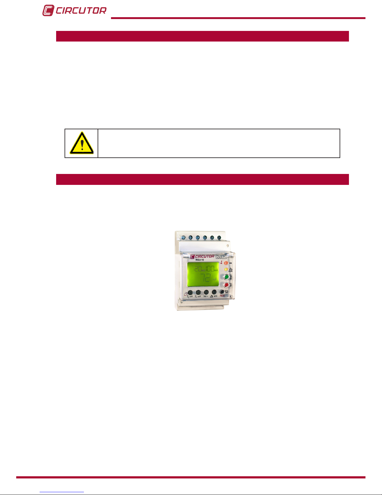
2�- DESCRIPTION OF THE PRODUCT
The RGU-10 earth leakage relay is type A programmable electronic earth leakage protection
device with two independent relays: the main output for checking the cut off device and perform-
ing the protection function and the pre-alarm relay for installation prevention and maintenance.
Allows the setting and adjustment of all parameters required for complete protection and main-
tenance checking in the installation. A series of parameters may be set directly from the key-
board (buttons) and by setting menus on the device itself.
Before starting the earth leakage device carefully read sections: power supply, connection dia-
gram and setting.
The RGU-10 measures, calculates and displays the earth leakage current in three-phase, bal-
anced or unbalanced industrial systems.
Measurements are in true effective value, via one earth leakage current input, from the WGC
family external measuring toroid.
Under normal operating conditions the main values determining earth leakage protection in an
installation are shown on the display. These include sensitivity, delay and instant current leak-
age.
Bearing in mind the high degree of protection required by installations, the device has a display

7
Instruction Manual
RGU-10, RGU-10C
and LED indicators for the different events which usually occur.
Datadisplayedorpre-alarmindication,trips,leakagereadings,etc.assistinprovidingsufcient
information for proper maintenance.
Under normal operating conditions the backlit display is green. However, after any event caus-
ing a main relay to trip, the backlight is red, indicating the reason.
The version for RS-485 communications (RGU-10C) and appropriate software allows setting,
data and information to centralised for the proper monitoring and checking of the maintenance
of electricity lines.
The measurement of earth leakage current from which the RGU-10/RGU-10C operates by
indicating the instant leakage current, pre-alarm or trip is determined by the WGC series earth
leakagetransformers.Theinnerdiameterofthetransformerisdenedbytheinstallation’swir-
ing dimensions.
There are 2 models of the device:
RGU-10, without communications.
RGU-10C, with communications RS-485.
Main features:
- Measuring in true effective value (TRMS)
- Type A differential (IEC 61008.1)
- Insulation against transients (IEC 61008.1)
-Highfrequencyltering(IEC61008.1)
-Tripsettingbetween80and100%I∆n
- Inverse curve (IEC 61008.1)
- Associated standard : IEC 61008.1, IEC755
- 3 modules. DIN rail. In a panel using front accessory
- Displaying instant leakage values.
- Backlit LCD display.
- RGU-10C Model : Built-in RS485 communications (Modbus RTU®).
8
RGU-10, RGU-10C
Instruction Manual
3�- INSTALLING THE DEVICE
3.1.- PRELIMINARY RECOMMENDATIONS
The operators using and handling the device must follow the safety measures
established in the country where the device will be used to guarantee its safe
operation, using personal protective equipment if needed.
The RGU-10devicemustbeinstalledbyauthorisedandqualiedstaff.
Disconnect the device from the mains and disconnect the measuring devices before handling,
changing the connections of or replacing the device. Handling the device while it is connected
is hazardous to people nearby.
The cables must be in perfect working order to prevent accidents or injuries to people and/or
damage to the facilities/installations.
Limittheoperationofthedevicetomeasuringthespeciedcurrentorvoltagevalues.
The manufacturer of the device shall not be held responsible for any damage resulting from the
user or installation company failing to observe the warnings and/or recommendations indicated
in this manual nor for any damage resulting from the use of non-original products or accesso-
ries or those from other brands.
Do not use the device to take measurements if you detect an anomaly or malfunction.
Check the environment in which the device is installed before taking a measurement. Do not
use the device to take measurements in dangerous, explosive, wet or damp environments.
Disconnect the device from the mains and from the power supply (both the device
and its measuring system) before performing any maintenance work, repairs or
handling any of the connections of the device.
Contact the after-sales service if you detect that the device is not working prop-
erly.

9
Instruction Manual
RGU-10, RGU-10C
3.2.- INSTALLATION
While the device is connected, the terminals, opening the cover or removing el-
ements can expose parts that are hazardous to the touch. The device must not
be used until the installation process is complete.
The device is installed on a DIN rail or on a panel (drilled panel 67+1 x 67+1mm, according to DIN
43 700 using accessory). All connections must remain inside the electrical board.
3�2�1�- INSTALLATION OF DEVICE IN PANEL
A 72x72 mm front adapter accessory is used to install the device on a panel. All connections
must remain inside the electrical board.
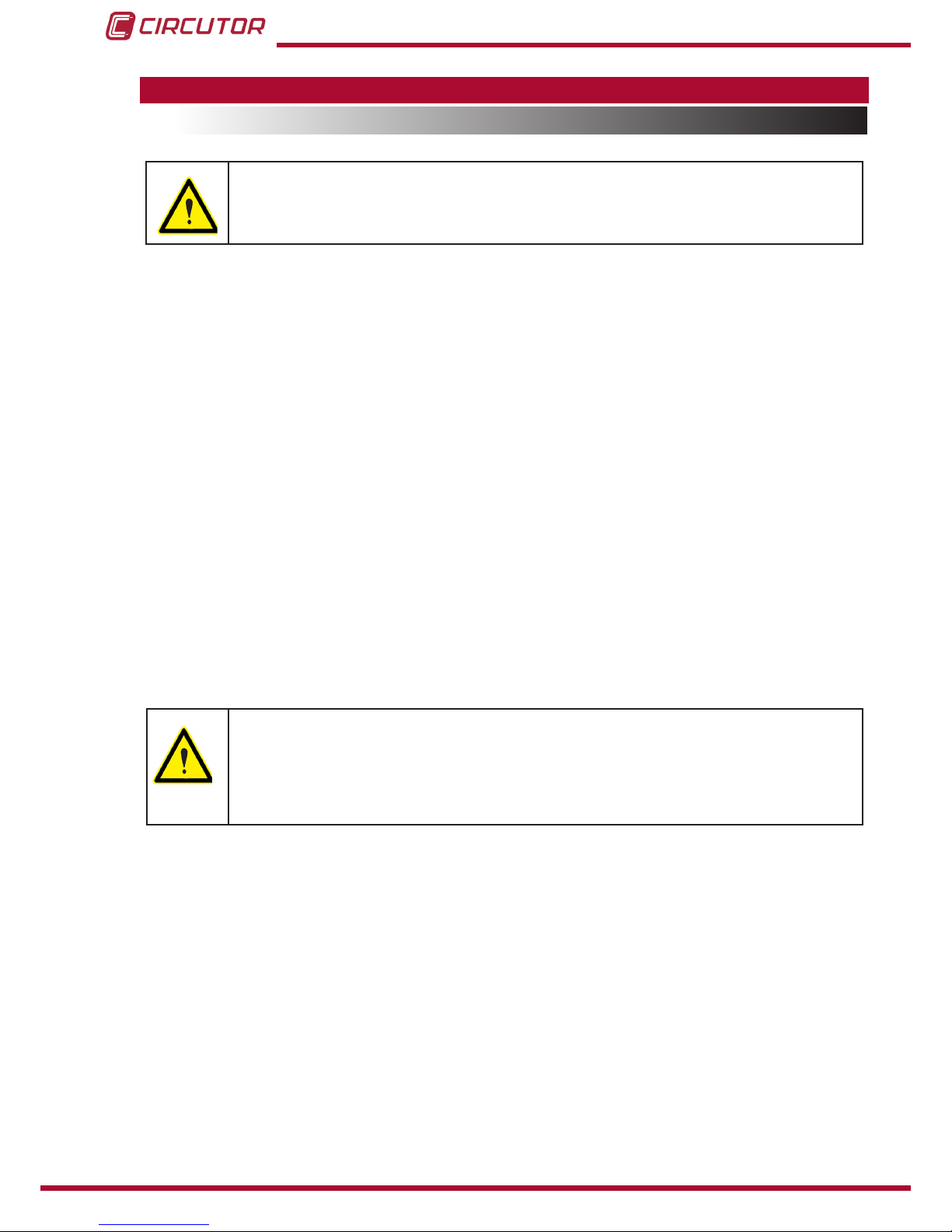
The front adapter accessory has a base, a frame two tabs and three screws, Figure 1.
Figure 1:Adapter accessory�
The steps to follow to perform the installation of the adapter accessory are:
1�- The base is mounted on top of the device.
2�- The device is attached by screwing the holes in the device on the upper right corner and
lower left corner on the front of device.
3�- The front frame is attached to cover the mounting points.
4�- Three green pressure tabs on the side runners of the base are attached.
5�- The device is mounted in the hole in the panel with the adapter.
6�- The tabs run towards the panel to obtain the mounting pressure.
10
RGU-10, RGU-10C
Instruction Manual
Figure 2: Installation of adapter accessory
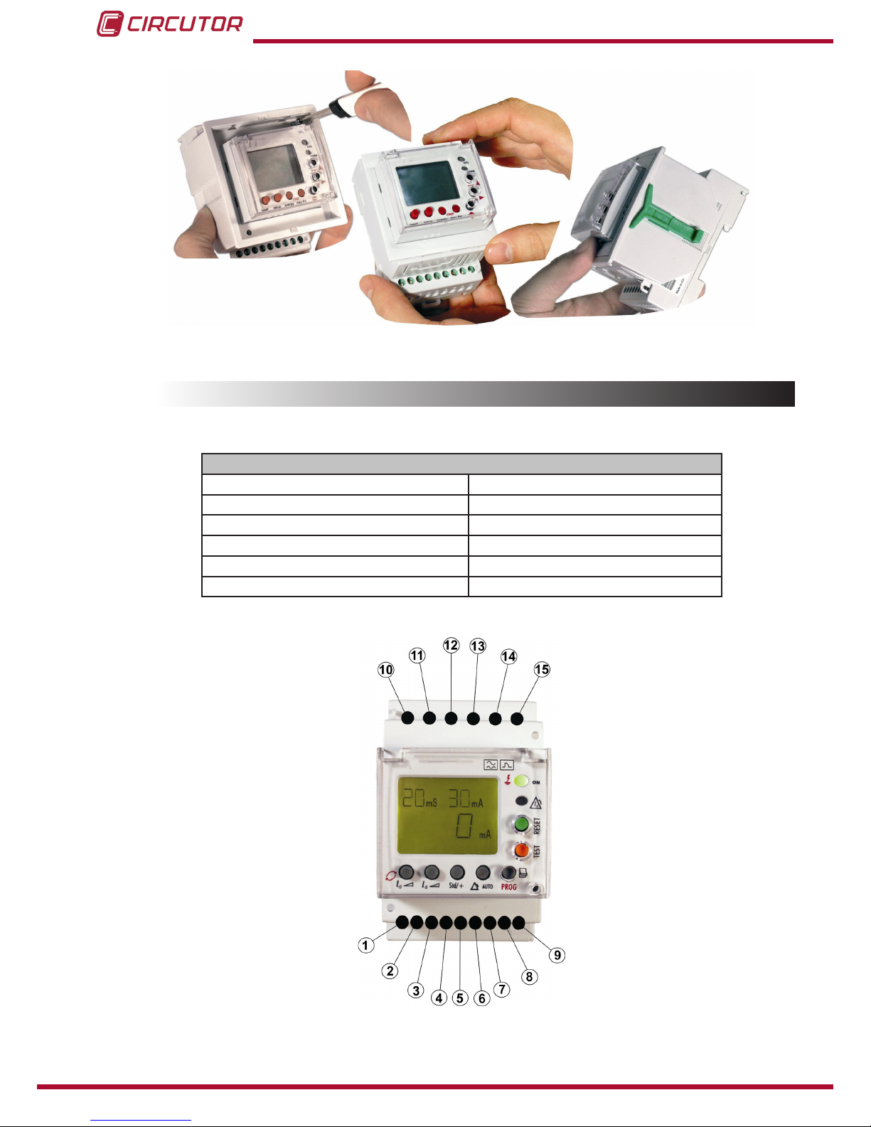
3.3.- TERMINALS OF THE DEVICE
Table 3:Terminal description RGU-10�
Terminals of the device
1: Voltage input ON/OFF external L 9: Toroid current input 1S2
2: Voltage input ON/OFF external N 10: Power supply voltage input A1
4: Output common contact pre-alarm 11: Power supply voltage input A2
5: NC output contact pre-alarm 13: NO output contact trip
6: NO output contact pre-alarm 14: NC output contact trip
8: Toroid current input 1S1 15: Output common contact trip
Note: Terminals 3, 7 and 12 are free.
Figure 3: RGU-10 terminals�
11
Instruction Manual
RGU-10, RGU-10C
3.4.- CONNECTION DIAGRAMS
Note : It is recommended that meshed cable is used to connect the toroid over large distances.
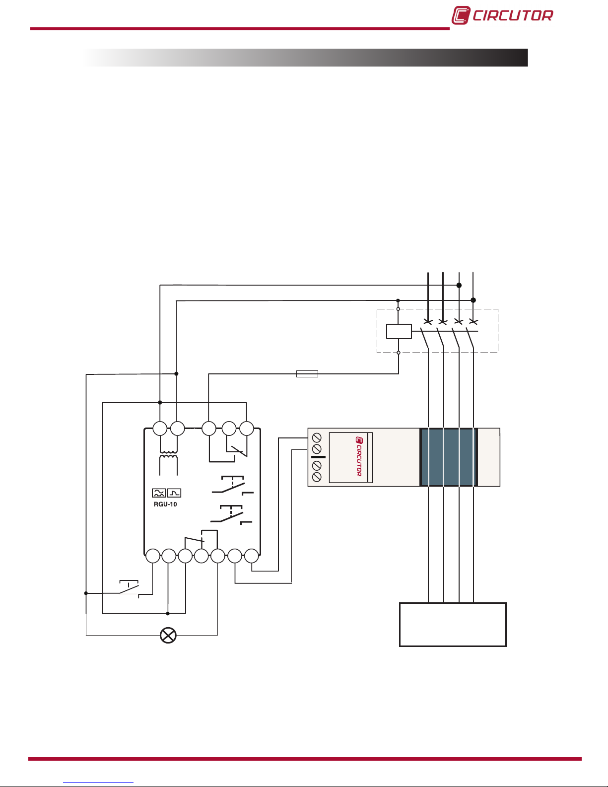
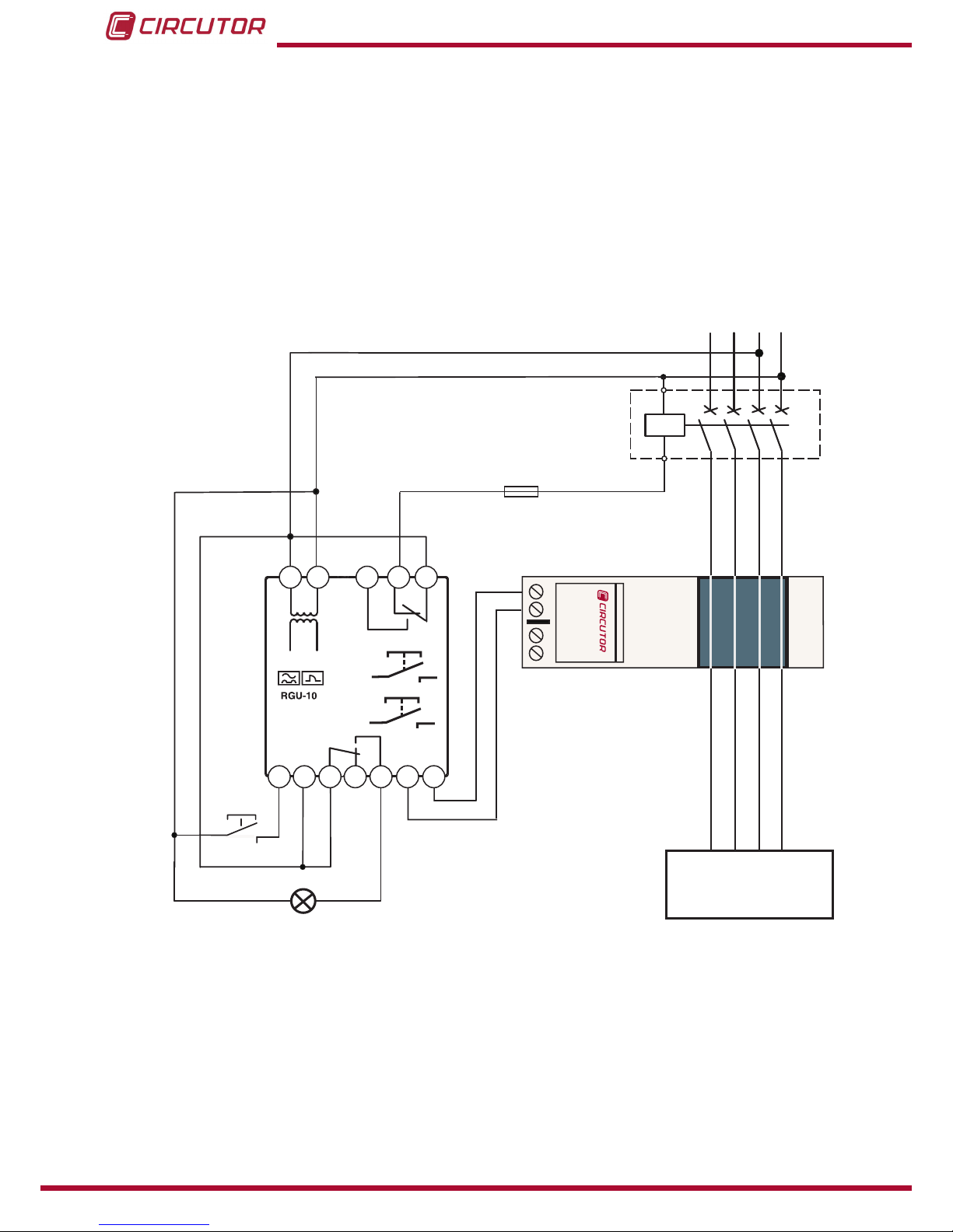
3�4�1�- CONNECTION WITH CURRENT EMISSION COIL
3�4�1�1�- Powering the device before the breaking device
In the event of powering the device before the breaking device (automatic switch) in an earth
leakage trip situation because of a fault, test or toroid error:
1�- Note the cause of the trip on the red display.
2�- Reset the breaking device.
3�- Press the RESET device.
NL1 L2 L3
1S1
1S2
Type
WGC
1S11S2
Reset
Test
1 2 4 5 6 8 9
10
11
13 14 15
UTILIZACIÓN
USE
ON / OFF externo
External ON / OFF
Disparo por BOBINA DE EMISIÓN
- Rearme Manual
Trip by SHUNT COIL
- Manual reclose
Figure 4: 24 ��� 230 Vac power supply

12
RGU-10, RGU-10C
Instruction Manual
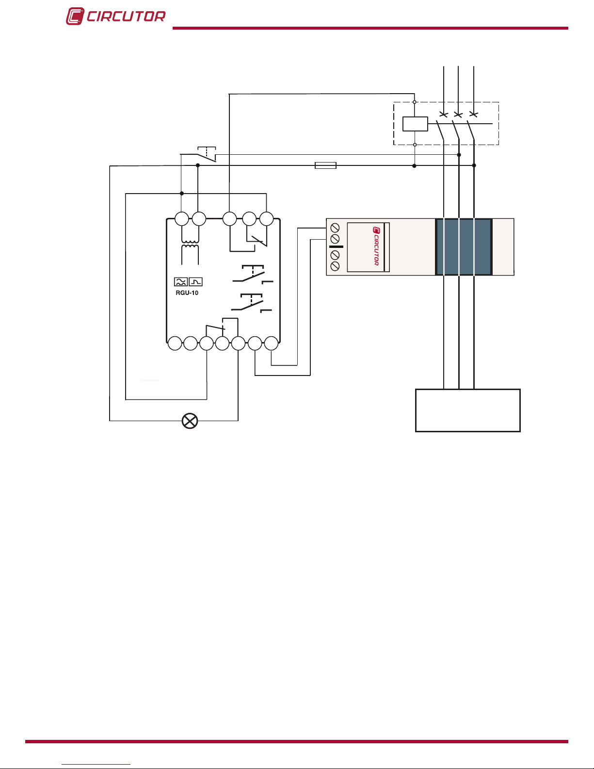
L1 L2 L3
1S1
1S2
Type
WGC
1S11S2
Reset
Test
1 2 4 5 6 8 9
10
11
13 14 15
UTILIZACIÓN
USE
Reset exterior
External Reset
Disparo por BOBINA DE EMISIÓN
- Rearme Manual
Trip by SHUNT COIL
- Manual reclose
Figure 5: 400 Vac power supply

13
Instruction Manual
RGU-10, RGU-10C
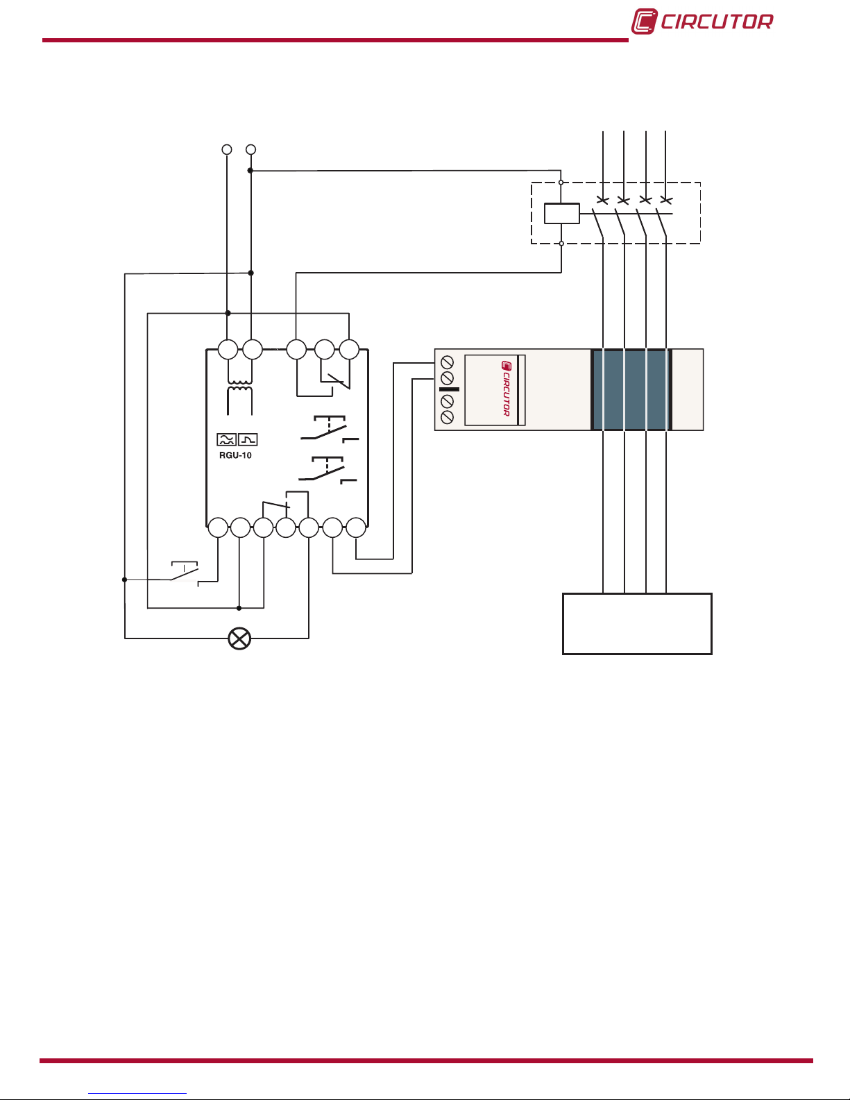
3�4�1�2�- Powering the device after the breaking device
The following has to be taken into consideration in the event of powering device after the break-
ing device.
1�- The breaking device has to be a manually resettable device.
2�- After dripping, the device is disconnected losing all information on the reasons for the trip.
The system is reset only by resetting the breaking device. It is reconnected by the power supply.
NL1 L2 L3
1S1
1S2
Type
WGC
1S11S2
Reset
Test
1 2 4 5 6 8 9
10
11
13 14 15
UTILIZACIÓN
USE
ON / OFF externo
External ON / OFF
Disparo por BOBINA DE EMISIÓN
- Rearme Automático mediante corte de
alimentación
Trip by SHUNT COIL
- Automatic reclose by power supply out
Figure 6: 24 ��� 230 Vac power supply
14
RGU-10, RGU-10C
Instruction Manual
L1 L2 L3
1S1
1S2
Type
WGC
1S11S2
Reset
Test
1 2 4 5 6 8 9
10
11
13 14 15
UTILIZACIÓN
USE
Disparo por BOBINA DE EMISIÓN
- Rearme Automático mediante corte de
alimentación
Trip by SHUNT COIL
- Automatic reclose by power supply out
Reset exterior
External Reset
Figure 7: 400 Vac power supply
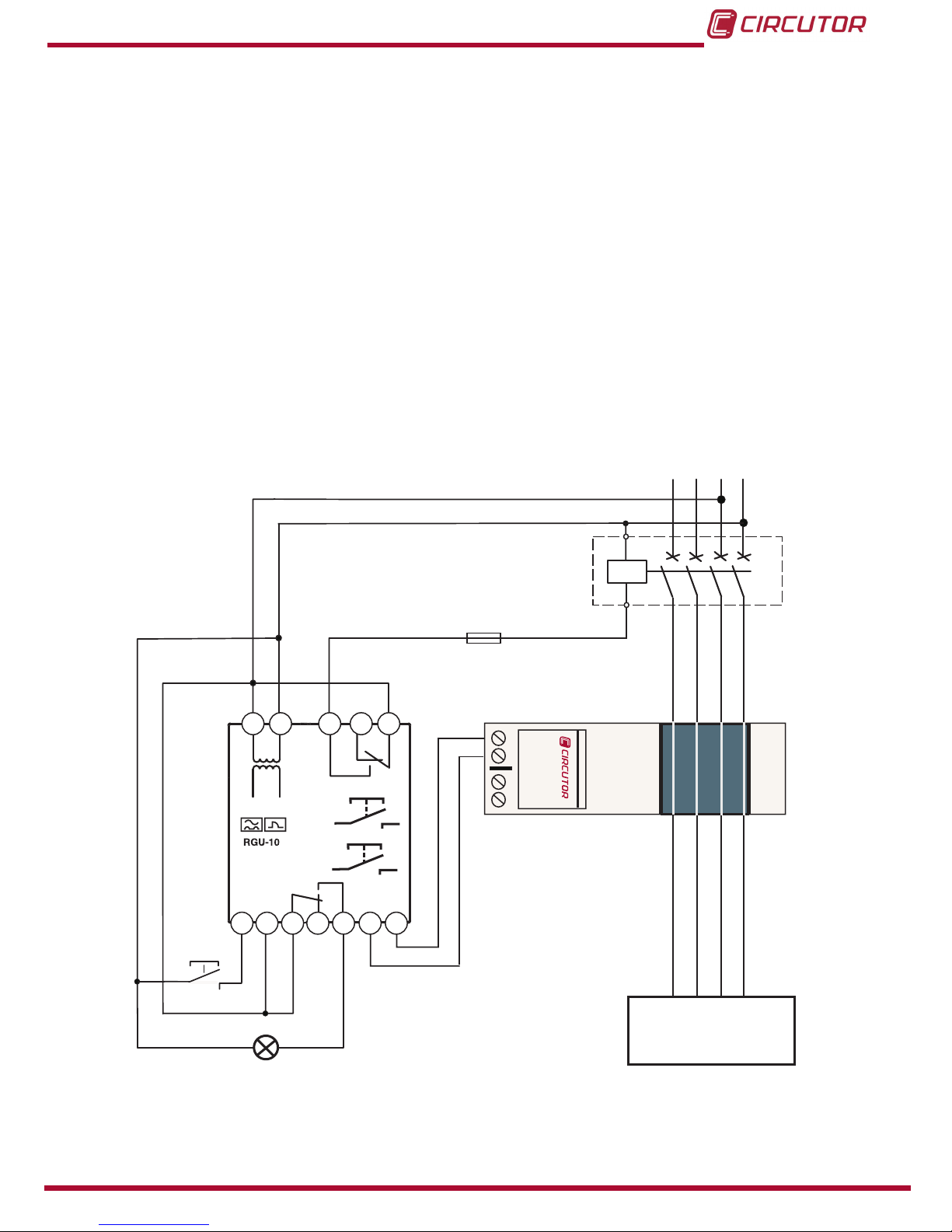
The device operates to its maximum whenever it is supplied from the installation itself before
the breaking device or from an independent auxiliary power supply. However if the power sup-
ply from the installation is below the breaking device the system continues to be properly pro-
tected even though with limitations in terms of its disconnection performance through lack of
power supply.
15
Instruction Manual
RGU-10, RGU-10C
3�4�1�3�- Power supply of the device independent of the installation
NL1 L2 L3
1S1
1S2
Type
WGC
1S11S2
Reset
Test
1 2 4 5 6 8 9
10
11
13 14 15
UTILIZACIÓN
USE
ON / OFF externo
External ON / OFF
Disparo por BOBINA DE EMISIÓN
- Rearme Manual
Trip by SHUNT COIL
- Manual reclose
+
-
Figure 8: 24 ��� 120 Vdc power supply

16
RGU-10, RGU-10C
Instruction Manual
3�4�2�- CONNECTION WITH UNDERVOLTAGE COIL
3�4�2�1�- Powering the device before the breaking device
This breaking device may be an automatic switch or contactor.
Using a Contactor the protection is reset by pressing RESET, or by using an automatic switch.
The breaking device must be rearmed beforehand.
NL1 L2 L3
1S1
1S2
Type
WGC
1S11S2
Reset
Test
1 2 4 5 6 8 9
10
11
13 14 15
UTILIZACIÓN
USE
ON / OFF externo
External ON / OFF
Disparo por BOBINA DE MÍNIMA
- Rearme Manual
Trip by UNDERVOLTAGE COIL
- Manual reclose
Figure 9: 24 ��� 230 Vac power supply

17
Instruction Manual
RGU-10, RGU-10C
L1 L2 L3
1S1
1S2
Type
WGC
1S11S2
Reset
Test
1 2 4 5 6 8 9
10
11
13 14 15
UTILIZACIÓN
USE
Reset exterior
External Reset
Disparo por BOBINA DE MÍNINA
- Rearme Manual
Trip by UNDERVOLTAGE COIL
- Manual reclose
Figure 10: 400 Vac power supply

18
RGU-10, RGU-10C
Instruction Manual
3�4�2�2�- Power supply of the device independent of the installation
NL1 L2 L3
1S1
1S2
Type
WGC
1S11S2
Reset
Test
1 2 4 5 6 8 9
10
11
13 14 15
UTILIZACIÓN
USE
ON / OFF externo
External ON / OFF
Disparo por BOBINA DE MíNIMA
- Rearme Manual
Trip by UNDERVOLTAGE COIL
- Manual reclose
+
-
Figure 11: 24 ��� 120 Vdc power supply
19
Instruction Manual
RGU-10, RGU-10C
3�4�3�- CONNECTING THE DEVICE IN POSITIVE SAFETY
This installation mode provides the most conservative protection from the point of view of per-
sonal and property safety in electrical installations.
With this type of device connection and setting, persons all goods are protected against faults
where the earth leakage relay loses its protection capacity. The last order from the relay is to
open the installation in the event of this power supply problems to the device itself or through
lack of voltage in the installation (neutral or face fault).
3�4�3�1�- Connection with undervoltage coil
1�- The breaking device has the power to trip using the undervoltage coil, either internally (con-
tactor) or externally (automatic switch).
2�- The device is set by programming by pressing Std/+ key in positive safety mode. The
“+”symbol appears on the display.
3�- The device’s power supply has to be the same as the installation or section it is protecting.
NL1 L2 L3
1S1
1S2
Type
WGC
1S11S2
Reset
Test
1 2 4 5 6 8 9
10
11
13 14 15
UTILIZACIÓN
USE
ON / OFF externo
External ON / OFF
Disparo por BOBINA DE MÍNIMA
- Rearme Manual
Trip by UNDERVOLTAGE COIL
- Manual reclose
Figure 12: Positive safety, undervoltage coil�
20
RGU-10, RGU-10C
Instruction Manual
3�4�3�2�- Connection with current emission coil
When this type of safety is used using the current emission coil, it can only be assured that the
system will trip went the earth leakage relay is not operating correctly.
1�- The breaking device has the power to trip using the maximum current coil (automatic
switch).
2�- The device is set by programming by pressing Std/+ key in positive safety mode. The “+”
symbol appears on the display.
NL1 L2 L3
1S1
1S2
Type
WGC
1S11S2
Reset
Test
1 2 4 5 6 8 9
10
11
13 14 15
UTILIZACIÓN
USE
ON / OFF externo
External ON / OFF
Disparo por BOBINA DE EMISIÓN
- Rearme Manual
Trip by SHUNT COIL
- Manual reclose
Figure 13: Positive safety, current emission coil�
Other manuals for RGU-10
4
This manual suits for next models
1
Table of contents
Other Circutor Other manuals

Popular Other manuals by other brands


KEUCO
KEUCO 17612 01 9002 Installation and operating instructions

Task Force Tips
Task Force Tips BLITZFIRE Series INSTRUCTIONS FOR SAFE OPERATION AND MAINTENANCE

Skyetek
Skyetek SkyeReader 300 user guide

Duesenberg
Duesenberg Les Trem II quick start guide

Martin Audio
Martin Audio AS118 - SCHEMATICS manual

LAMBORGHINI
LAMBORGHINI LED 24 MB W TOP - SCHEMA manual


