Cardin Elettronica EL Series User manual

ZVL421.03 Mod: 26-07-2004
BARRIERA ELETTROMECCANICA PER ASTA DA 3-4-6 m
ELECTROMECHANICAL BARRIER FOR 3 m, 4 m AND 6 m BOOMS
BARRIÈRE LEVANTE ÉLECTROMÉCANIQUE POUR LISSE DE 3 m, 4 m ET 6 m
ELEKTROMECHANISCHE SCHRANKE FÜR 3 m, 4 m UND 6 m BALKEN
BARRERA ELECTROMECÁNICA PARA BARRA DE 3 m, 4 m Y 6 m
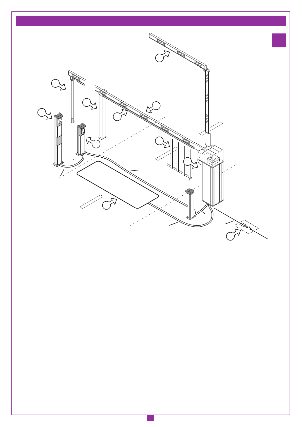
Impianto tipo Pagina 2
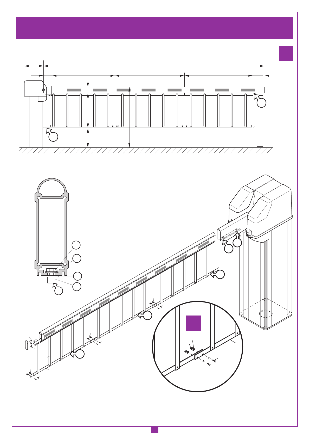
Schema di montaggio barriera e asta Pagina 3-7
Equilibratura dell'asta Pagina 8
Regolazione asta Pagina 9-10
Manovra manuale Pagina 10
Schema elettrico impianto tipo Pagina 11
Avvertenze importanti Pagina 12
Considerazioni generali di sicurezza Pagina 12
Istruzioni per l'uso Pagina 13
Istruzioni per l'installazione Pagina 13-15
Collegamento elettrico Pagina 15
Caratteristiche tecniche Pagina 32
Installation example Page 2
Barrier and boom assembly drawings Page 3-7
Balancing the boom Page 8
Adjusting the boom Page 9-10
Manual manoeuvre Page 10
Standard wiring diagram Page 11
Important remarks Page 16
Important safety instructions Page 16
User instructions Page 17
Installation instructions Page 17-19
Electrical connection Page 19
Technical specifications Page 32
Exemple d'installation Page 2
Schéma de montage de la lisse et de la barrière Page 3-7
Équilibrage de la lisse Page 8
Réglage de la lisse Page 9-10
Manoeuvre manuelle Page 10
Schéma électrique de l'exemple d'installation Page 11
Consignes importantes Page 20
Consignes générales de sécurité Page 20
Instructions pour l'utilisation Page 21
Instructions pour l'installation Page 21-23
Branchement électrique Page 23
Caractéristiques techniques Page 32
Anlagenart Seite 2
Befestigung des Balkens und der Schranke Seite 3-7
Ausbalancierung des Balkens Seite 8
Einstellung des Balkens Seite 9-10
Manuelle Betätigung Seite 10
Elektrischer schaltplan (Anlagenart) Seite 11
Wichtige Hinweise Seite 24
Allgemeine Sicherheitsvorgaben Seite 24
Betriebsanleitungen Seite 25
Installationsanleitungen Seite 25-27
Elektrischer anschluss Seite 27
Technische Daten Seite 32
Instalación estándar Página 2
Esquema de montaje barra y barrera Página 3-7
Equilibrado de la barra Página 8
Regulación de la barra Página 9-10
Maniobra manual Página 10
Esquema electrico instalación estándar Página 11
Advertencias importantes Página 28
Advertencias generales sobre la seguridad Página 28
Instrucciones para el uso Página 29
Instrucciones para la instalación Página 29-31
Conexión electrica Página 31
Caracteristicas técnicas Página 32
230Vac
Motors
ITALIANO
ENGLISH ESPAÑOL
DEUTSCH
FRANÇAIS
CARDIN ELETTRONICA spa
Via Raffaello, 36
31020 San Vendemiano (TV) Italy
Tel: +39/0438.404011-401818
Fax: +39/0438.401831
email (Italian): Sales.of[email protected]
email (Europe): Sales.office@cardin.it
Http: www.cardin.it
Instruction manual Model
ZVL421.03
Series Date
10-07-2004
Questo prodotto è stato testato e collaudato nei laboratori della casa costruttrice, la quale ne ha verificato la
perfetta corrispondenza delle caratteristiche con quelle richieste dalla normativa vigente.
This product has been tried and tested in the manufacturer's laboratory who have verified that the product
conforms in every aspect to the safety standards in force.
Ce produit a été testé et essayé dans les laboratoires du fabriquant. Pour l'installer suivre attentivement
les instructions fournies.
Dieses Produkt wurde in den Werkstätten der Herstellerfirma auf die perfekte Übereinstimmung ihrer
Eigenschaften mit den von den geltenden Normen vorgeschriebenen getestet und geprüft.
Este producto ha sido probado y ensayado en los laboratorios del fabricante, que ha comprobado la perfecta
correspondencia de sus características con las contempladas por la normativa vigente.
EL
EL
230Vac
Motors
Series
3-4-6 m
710/EL313C
710/EL413C
710/EL613

2
IMPIANTO TIPO- INSTALLATION EXAMPLE - EXEMPLE D'INSTALLATION - ANLAGENART - INSTALACIÓN ESTÁNDAR
ZEICHENERKLÄRUNG
1 Schranke
2 Schlüsselschalter
3 Lichtschranken
4 Allpoliger Schalter mit einem Kontaktenabstand von mindestens 3 mm
5 Induktionsschliefe
6 Standardbalken
7 Gelenkbalken
8 Bewegliche Stütze
9 Feste Stütze
10 Zaun
11 Gummiprofil
LEYENDA
1 Barrera
2 Selector a llave
3 Fotocélulas
4 Interruptor omnipolar con apertura de contactos mín. 3 mm.
5 Sensor magnético
6 Asta estándar
7 Asta articulada
8 Apoyo móvil
9 Apoyo fijo
10 Rastrillera
11 Banda sensible
1
prodotti Technocity (lamp. fotocellule ecc.)
EL312/413/613
11-05-2001
DI0218
INSTALLAZIONE TIPO EL
1
2
8
9
10
4
5
11
7
6
3
Description :
Product Code :
Date :
Drawing number :
P.J.Heath
CARDIN ELETTRONICA S.p.A - 31020 San Vendemiano (TV) Italy - via Raffaello, 36 Tel: 0438/401818 Fax: 0438/401831
Draft :
All rights reserved. Unauthorised copying or use of the information contained in this document is punishable by law
TX RX
230V-50Hz
5x1
2x1,5
4x1
2x1,5+T
MWZ
3x1
LEGENDA
1 Barriera
2 Selettore a chiave
3 Fotocellule
4 Interruttore onnipolare con apertura contatti min. 3 mm
5 Sensore magnetico
6 Asta standard
7 Asta snodata
8 Appoggio mobile
9 Appoggio fisso
10 Siepe
11 Profilo in gomma
LEGEND
1 Barrier
2 Selector switch
3 Photocells
4 All pole circuit breaker with a min. of 3 mm between the contacts
5 Magnetic sensor
6 Standard boom
7 Articulated boom
8 Mobile support fork
9 Fixed support fork
10 Retractile mesh
11 Rubber buffer
NOMENCLATURE
1 Barrière
2 Sélecteur à clé
3 Cellule photoélectrique
4 Interrupteur omnipolaire, ouverture des contacts min. 3 mm
5 Senseur magnétique
6 Lisse standard
7 Lisse articulée
8 Support mobile
9 Lyre de repos
10 Grille rabattable
11 Profil en caoutchouc

3
SCALA:
Prodotti Technocity
SERIE EL
06-11-2001
DI0197 Description :
Product Code :
Date :
Drawing number :
P.J.Heath
CARDIN ELETTRONICA S.p.A - 31020 San Vendemiano (TV) Italy - via Raffaello, 36 Tel: 0438/401818 Fax: 0438/401831
Draft :
All rights reserved. Unauthorised copying or use of the information contained in this document is punishable by law
Schema di montaggio EL
310 410
300
220
270
275
325
220
270
220
270
1170
910
910
300 355
410
TECHNOCITY
3 - 4 m 6 m
2c
2a 2b
FISSAGGIO BASE BARRIERA AL PLINTO DI FONDAZIONE - FASTENING THE BASE OF THE BARRIER TO THE PLINTH
FIXATION DE LA BASE DE LA BARRIÈRE À L’ASSISE - BEFESTIGUNG DER SCHRANKENBASIS AN DER FUNDAMENTPLATTE
FIJACIÓN BASE BARRERA EN EL PLINTO DE CIMENTACIÓN
SCALA:
Prodotti Technocity
SERIE EL
06-11-2001
DI0190 Description :
Product Code :
Date :
Drawing number :
P.J.Heath
CARDIN ELETTRONICA S.p.A - 31020 San Vendemiano (TV) Italy - via Raffaello, 36 Tel: 0438/401818 Fax: 0438/401831
Draft :
All rights reserved. Unauthorised copying or use of the information contained in this document is punishable by law
Fissaggio barriera EL
350 (
EL 313C/413C
)
350 (EL 613)
270 (EL 613)
270 (EL 313C/413C)
40 40
270 (EL313C/413C)
40 40
325 (EL 613)
50
C
B
A
350 (EL 313C/413C)
405 (EL 613)
SCALA:
Prodotti Technocity
SERIE EL
06-11-2001
DI0191 Description :
Product Code :
Date :
Drawing number :
P.J.Heath
CARDIN ELETTRONICA S.p.A - 31020 San Vendemiano (TV) Italy - via Raffaello, 36 Tel: 0438/401818 Fax: 0438/401831
Draft :
All rights reserved. Unauthorised copying or use of the information contained in this document is punishable by law
Fissaggio base barriera EL
30
30
30
D

4
SCALA:
Prodotti Technocity
SERIE EL
12-07-2004
DI0348 Description :
Product Code :
Date :
Drawing number :
P.J.Heath
CARDIN ELETTRONICA S.p.A - 31020 San Vendemiano (TV) Italy - via Raffaello, 36 Tel: 0438/401818 Fax: 0438/401831
Draft :
All rights reserved. Unauthorised copying or use of the information contained in this document is punishable by law
Schema di montaggio EL
4
2
3
D
E
C
M8x16
A
B
C
1
5
SCHEMA DI MONTAGGIO ASTA 3-4-6 m - ASSEMBLY DRAWINGS 3-4-6 m BOOM - SCHÉMA DE MONTAGE DE LA LISSE DE 3-4-6 m
MONTAGESCHEMA DES 3-4-6 m-BALKENS - ESQUEMA DE MONTAJE DE LA BARRA DE 3-4-6 m
3a
3b
3c
G
H
SCALA:
Prodotti Technocity
SERIE EL
12-07-2004
DI0351 Description :
Product Code :
Date :
Drawing number :
P.J.Heath
CARDIN ELETTRONICA S.p.A - 31020 San Vendemiano (TV) Italy - via Raffaello, 36 Tel: 0438/401818 Fax: 0438/401831
Draft :
All rights reserved. Unauthorised copying or use of the information contained in this document is punishable by law
Schema di montaggio Presostato
ø 3 mm
L

5
SCALA:
Prodotti Technocity
SERIE EL
19-07-2004
DI0352 Description :
Product Code :
Date :
Drawing number :
P.J.Heath
CARDIN ELETTRONICA S.p.A - 31020 San Vendemiano (TV) Italy - via Raffaello, 36 Tel: 0438/401818 Fax: 0438/401831
Draft :
All rights reserved. Unauthorised copying or use of the information contained in this document is punishable by law
Schema di montaggio asta snodata
con tappo nuova.
29
20
17
7
18
22
8
16
16
20
16
57
14
13
9
16
4
31 28
27
28
25
24
10
11
4
6
2
1
3
12
15
19
21
32
30
14
Q
P
SCHEMA DI MONTAGGIO ASTA SNODATA - ASSEMBLY DRAWINGS ARTICULATED BOOM - SCHÉMA DE MONTAGE DE LA LISSE ARTICULÉE
MONTAGESCHEMA DES GELENKBALKENS- ESQUEMA DE MONTAJE DE LA ASTA ARTICULADA
4a
SCALA:
Prodotti Technocity
SERIE EL
14-11-2001
DI0199 Description :
Product Code :
Date :
Drawing number :
P.J.Heath
CARDIN ELETTRONICA S.p.A - 31020 San Vendemiano (TV) Italy - via Raffaello, 36 Tel: 0438/401818 Fax: 0438/401831
Draft :
All rights reserved. Unauthorised copying or use of the information contained in this document is punishable by law
Schema di montaggio asta snodata
EL
3360
3000
1500
2600
1500 90
30 mm
980
2570
1500
330 30
TECHNOCITY
By Cardin
TECHNOCITY
B y C a r d i n
TECHNOCITY
B y C a r d i n
TECHNOCITY
B y C a r d i n
TECHNOCITY
B y C a r d i n
TECHNOCITY
B y C a r d i n
200
1170
1400
400
4b
4c

6
SCHEMA DI MONTAGGIO ASTA DA 6 m CON SIEPE - ASSEMBLY DRAWINGS 6 m BOOM WITH RETRACTABLE MESH
SCHÉMA DE MONTAGE DE LA LISSE DE 6 m AVEC GRILLE RABATTABLE - MONTAGESCHEMA DES 6 m-BALKENS MIT
HÄNGEGITTER - SQUEMA DE MONTAJE DE LA BARRA DE 6 m CON RASTRILLERA
5
SCALA:
Prodotti Technocity
SERIE EL
15-11-2001
DI0204 Description :
Product Code :
Date :
Drawing number :
P.J.Heath
CARDIN ELETTRONICA S.p.A - 31020 San Vendemiano (TV) Italy - via Raffaello, 36 Tel: 0438/401818 Fax: 0438/401831
Draft :
All rights reserved. Unauthorised copying or use of the information contained in this document is punishable by law
Schema di montaggio Asta da 6 metri
12
10
11 5
1211
10
1211
10
S
S
T
4
6
7
8
9
Z
Z
T E CHNOCIT Y
B y Car d in
TE C HNOCITY
B y C a r d i n
T E CHNOCIT Y
B y C a r d in
TECHNOCIT Y
B y C a r d in
TECHNOC I TY
B y Car d in
TE C HNOC I T Y
B y Car d in
TECHNOC I TY
B y Car d in
T E CHNOCITY
By C ar d in
TECHNOCITY
By Car d in
SCALA:
Prodotti Technocity
SERIE EL
15-11-2001
DI0205 Description :
Product Code :
Date :
Drawing number :
P.J.Heath
CARDIN ELETTRONICA S.p.A - 31020 San Vendemiano (TV) Italy - via Raffaello, 36 Tel: 0438/401818 Fax: 0438/401831
Draft :
All rights reserved. Unauthorised copying or use of the information contained in this document is punishable by law
Schema di montaggio Siepe per
asta da 6 metri
230
360
1778 310
1778 1904
6000
100
600
1050
350
R
U
SCALA:
Prodotti Technocity
SERIE EL
15-11-2001
DI0203 Description :
Product Code :
Date :
Drawing number :
P.J.Heath
CARDIN ELETTRONICA S.p.A - 31020 San Vendemiano (TV) Italy - via Raffaello, 36 Tel: 0438/401818 Fax: 0438/401831
Draft :
All rights reserved. Unauthorised copying or use of the information contained in this document is punishable by law
Schema di montaggio Fermo siepe
R
R1
R2
R3
R4
SCALA:
Prodotti Technocity
SERIE EL
15-11-2001
DI0223 Description :
Product Code :
Date :
Drawing number :
P.J.Heath
CARDIN ELETTRONICA S.p.A - 31020 San Vendemiano (TV) Italy - via Raffaello, 36 Tel: 0438/401818 Fax: 0438/401831
Draft :
All rights reserved. Unauthorised copying or use of the information contained in this document is punishable by law
Asta da 4M con sieppe (datt)
1211 5
10
5a

7
SCALA:
Prodotti Technocity
SERIE EL
15-11-2001
DI0208 Description :
Product Code :
Date :
Drawing number :
P.J.Heath
CARDIN ELETTRONICA S.p.A - 31020 San Vendemiano (TV) Italy - via Raffaello, 36 Tel: 0438/401818 Fax: 0438/401831
Draft :
All rights reserved. Unauthorised copying or use of the information contained in this document is punishable by law
Schema di montaggio appoggio
mobile
1
2
3
6
7
8
9
10 11 4
5
R
EL613
EL
313C-EL413C
U
W
SCALA:
Prodotti Technocity
SERIE EL
15-11-2001
DI0207 Description :
Product Code :
Date :
Drawing number :
P.J.Heath
CARDIN ELETTRONICA S.p.A - 31020 San Vendemiano (TV) Italy - via Raffaello, 36 Tel: 0438/401818 Fax: 0438/401831
Draft :
All rights reserved. Unauthorised copying or use of the information contained in this document is punishable by law
Schema di montaggio appoggio fisso
933
80x80
S
SCHEMA DI MONTAGGIO APPOGGIO FISSO- ASSEMBLY DRAWINGS FIXED SUPPORT - SCHÉMA DE MONTAGE DE LA LYRE DE REPOS
MONTAGESCHEMA DER AUFLAGESTÜTZEN - ESQUEMA DE MONTAJE DEL APOYO FIJO
6
SCALA:
Prodotti Technocity
SERIE EL
15-11-2001
DI0205 Description :
Product Code :
Date :
Drawing number :
P.J.Heath
CARDIN ELETTRONICA S.p.A - 31020 San Vendemiano (TV) Italy - via Raffaello, 36 Tel: 0438/401818 Fax: 0438/401831
Draft :
All rights reserved. Unauthorised copying or use of the information contained in this document is punishable by law
Schema di montaggio Siepe per
asta da 6 metri
356
3000 - 4000 -6000
933
60
150
90
S
360
T
SCALA:
Prodotti Technocity
SERIE EL
15-11-2001
DI0209 Description :
Product Code :
Date :
Drawing number :
P.J.Heath
CARDIN ELETTRONICA S.p.A - 31020 San Vendemiano (TV) Italy - via Raffaello, 36 Tel: 0438/401818 Fax: 0438/401831
Draft :
All rights reserved. Unauthorised copying or use of the information contained in this document is punishable by law
Schema di montaggio appoggio
mobile
360 3000 - 4000 - 6000
933 98
50
T
SCHEMA DI MONTAGGIO APPOGGIO MOBILE - ASSEMBLY DRAWINGS MOBILE SUPPORT - SCHÉMA DE MONTAGE - MONTAGE
SCHEMA DI MONTAGGIO APPOGGIO MOBILE - ASSEMBLY DRAWINGS MOBILE SUPPORT - SCHÉMA DE MONTAGE DU SUPPORT MOBILE
MONTAGESCHEMA DER PENDELSTÜTZE - ESQUEMA DE MONTAJE DEL APOYO MÓVIL
8
7
6a
7a

8
SCALA:
Prodotti Technocity
SERIE EL
19-11-2001
DI0220 Description :
Product Code :
Date :
Drawing number :
P.J.Heath
CARDIN ELETTRONICA S.p.A - 31020 San Vendemiano (TV) Italy - via Raffaello, 36 Tel: 0438/401818 Fax: 0438/401831
Draft :
All rights reserved. Unauthorised copying or use of the information contained in this document is punishable by law
Equilibratura dell'asta
Q1
X
M1
SCALA:
Prodotti Technocity
SERIE EL
19-11-2001
DI0222 Description :
Product Code :
Date :
Drawing number :
P.J.Heath
CARDIN ELETTRONICA S.p.A - 31020 San Vendemiano (TV) Italy - via Raffaello, 36 Tel: 0438/401818 Fax: 0438/401831
Draft :
All rights reserved. Unauthorised copying or use of the information contained in this document is punishable by law
Equilibratura dell'asta "X"
Q1
X1
M1
APERTURA CALOTTA SUPERIORE E PORTELLO ANTERIORE - OPENING THE UPPER COVER AND FRONT PANEL
OUVERTURE DU CAPOT ET DU PORTILLON ANTÉRIEUR - ÖFFNEN DER ABDECKHAUBE UND DER VORDEREN TÜR
APERTURA CASQUETE SUPERIOR Y PORTILLO ANTERIOR
EQUILIBRATURA DELL'ASTA - BALANCING THE BOOM - ÉQUILIBRAGE DE LA LISSE
AUSBALANCIERUNG DES BALKENS - EQUILIBRADO DE LA BARRA
8
9
SCALA:
Prodotti Technocity
SERIE EL
15-11-2001
DI0210 Description :
Product Code :
Date :
Drawing number :
P.J.Heath
CARDIN ELETTRONICA S.p.A - 31020 San Vendemiano (TV) Italy - via Raffaello, 36 Tel: 0438/401818 Fax: 0438/401831
Draft :
All rights reserved. Unauthorised copying or use of the information contained in this document is punishable by law
Apertura calotta superiore
U
L
L
SCALA:
Prodotti Technocity
SERIE EL
15-11-2001
DI0211 Description :
Product Code :
Date :
Drawing number :
P.J.Heath
CARDIN ELETTRONICA S.p.A - 31020 San Vendemiano (TV) Italy - via Raffaello, 36 Tel: 0438/401818 Fax: 0438/401831
Draft :
All rights reserved. Unauthorised copying or use of the information contained in this document is punishable by law
Apertura calotta superiore
V

9
REGOLAZIONE MECCANICA DELLA POSIZIONE ORIZZONTALE ASTA - ADJUSTING THE HORIZONTAL POSITION OF THE BOOM
RÉGLAGE MÉCANIQUE DE LA POSITION HORIZONTALE DE LA LISSE - MECHANISCHE EINSTELLUNG DER WAAGERECHTEN
BALKENSTELLUNG - REGULACIÓN MECÁNICA DE LA POSICIÓN HORIZONTAL DE LA BARRA
REGOLAZIONE TRAMITE MICROINTERUTTORE DI FINECORSA DELLA POSIZIONE VERTICALE ASTA - ADJUSTING THE VERTICAL POSITION
OF THE BOOM USING A TRAVEL LIMIT MICROSWITCH - RÉGLAGE À TRAVERS MICRO-INTERRUPTEUR DE FIN DE COURSE DE LA POSITION
VERTICALE DE LA LISSE - EINSTELLUNG DER SENKRECHTE STELLUNG DES BALKENS, MITTELS DEN MIKRO-ENDSCHALTER
REGULACIÓN MEDIANTE MICROINTERRUPTOR DE TOPE DE LA POSICIÓN VERTICAL DE LA BARRA
11
SCALA:
Prodotti Technocity
SERIE EL
15-11-2001
DI0212 Description :
Product Code :
Date :
Drawing number :
P.J.Heath
CARDIN ELETTRONICA S.p.A - 31020 San Vendemiano (TV) Italy - via Raffaello, 36 Tel: 0438/401818 Fax: 0438/401831
Draft :
All rights reserved. Unauthorised copying or use of the information contained in this document is punishable by law
Regolazione meccanica della
posizione orizzontale asta
J
Z
KW
J
Z
KW
Y
Y
SCALA:
Prodotti Technocity
SERIE EL
15-11-2001
DI0213 Description :
Product Code :
Date :
Drawing number :
P.J.Heath
CARDIN ELETTRONICA S.p.A - 31020 San Vendemiano (TV) Italy - via Raffaello, 36 Tel: 0438/401818 Fax: 0438/401831
Draft :
All rights reserved. Unauthorised copying or use of the information contained in this document is punishable by law
Regolazione meccanica della
posizione verticale asta
max compression 1 mm
X
A1
Y
SCALA:
Prodotti Technocity
SERIE EL
19-11-2001
DI0214 Description :
Product Code :
Date :
Drawing number :
P.J.Heath
CARDIN ELETTRONICA S.p.A - 31020 San Vendemiano (TV) Italy - via Raffaello, 36 Tel: 0438/401818 Fax: 0438/401831
Draft :
All rights reserved. Unauthorised copying or use of the information contained in this document is punishable by law
Regolazione meccanica della
posizione verticale asta
D1
C1
B1
E1
W
W
12
10a
10b

10
SCALA:
Prodotti Technocity
SERIE EL
19-11-2001
DI0217 Description :
Product Code :
Date :
Drawing number :
P.J.Heath
CARDIN ELETTRONICA S.p.A - 31020 San Vendemiano (TV) Italy - via Raffaello, 36 Tel: 0438/401818 Fax: 0438/401831
Draft :
All rights reserved. Unauthorised copying or use of the information contained in this document is punishable by law
Manovra manuale EL302V
Close
Chiude
Open
Apre
G
SCALA:
Prodotti Technocity
SERIE EL
26-03-2003
DI0281 Description :
Product Code :
Date :
Drawing number :
P.J.Heath
CARDIN ELETTRONICA S.p.A - 31020 San Vendemiano (TV) Italy - via Raffaello, 36 Tel: 0438/401818 Fax: 0438/401831
Draft :
All rights reserved. Unauthorised copying or use of the information contained in this document is punishable by law
Vite di sicurezza
F1
L1
L1
F1
F2
VITE DI SICUREZZA - SAFETY SCREW - VIS DE SÉCURITÉ
SICHERHEITSSCHRAUBE - TORNILLO DE SEGURIDAD
MANOVRA MANUALE - MANUAL MANOEUVRE- MANŒUVRE MANUELLE - MANUELLE BETÄTIGUNG - MANIOBRA MANUAL
13
15
SCALA:
Prodotti Technocity
SERIE EL
19-11-2001
DI0216 Description :
Product Code :
Date :
Drawing number :
P.J.Heath
CARDIN ELETTRONICA S.p.A - 31020 San Vendemiano (TV) Italy - via Raffaello, 36 Tel: 0438/401818 Fax: 0438/401831
Draft :
All rights reserved. Unauthorised copying or use of the information contained in this document is punishable by law
Manovra manuale
Close
Chiude
Open
Apre
F
G
• Avvitare il dado con chiave dinamometrica
(asta 3m = 30N; asta 4m = 40N; asta 6m = 55N)
• Screw in the nut using a dynometrical spanner
(3m - boom = 30N; 4m - boom = 40N; 6m - boom = 55N)
• Visser le écrou au moyen d'une clé dynamométrique
(lisse 3m = 30N; lisse 4m = 40N; lisse 6m = 55N)
• Die Schraubenmutter mit dem Drehmomentschlüssel festziehen
(3m-Balken = 30N; lisse 4m-Balken = 40N; lisse 6m-Balken = 55N)
• Atornillar la tuerca con llave dinamométrica
(asta 3m = 30N; asta 4m = 40N; asta 6m = 55N)
SCALA:
Prodotti Technocity
SERIE EL
06-11-2001
DI0193 Description :
Product Code :
Date :
Drawing number :
P.J.Heath
CARDIN ELETTRONICA S.p.A - 31020 San Vendemiano (TV) Italy - via Raffaello, 36 Tel: 0438/401818 Fax: 0438/401831
Draft :
All rights reserved. Unauthorised copying or use of the information contained in this document is punishable by law
Montaggio set lampeggiante EL
L
M
N
O
HH1
Fondo: Argento
Scrittura: Nero
Bordo: Nessun
Targhetta Max watt kit lampeggiatore
19-011-2001
ZVE418 Description :
Product Code :
Date:
Drawing number :
P.J.Heath
CARDIN ELETTRONICA S.p.A - 31020 San Vendemiano (TV) Italy - via Raffaello, 36 Tel: 0438/401818 Fax: 0438/401831
Draft :
All rights reserved. Unauthorised copying or use of the information contained in this document is punishable by law
SERIE EL
Max 40W
230Vac
MONTAGGIO SET LAMPEGGIANTE - ASSEMBLING THE WARNING
LIGHTS - MONTAGE DU KIT FEUX DE SIGNALISATION
MONTAGESCHEMA DES BLINKLICHT-BAUSATZES - MONTAJE DEL
SET LUCES INTERMITENTES
14

11
SCHEMA ELETTRICO IMPIANTO TIPO - STANDARD WIRING DIAGRAM - SCHÉMA ÉLECTRIQUE DE L'EXEMPLE D'INSTALLATION
ELEKTRISCHER SCHALTPLAN (ANLAGENART) - ESQUEMA ELECTRICO INSTALACIÓN ESTÁNDAR
16
LEGENDA
BSP1 Blocco sicurezza cofano
BSP2 Blocco sicurezza porta
FTC-RX Fotocellula ricevitore
FTC-TX Fotocellula trasmettitore
FCA Finecorsa di apertura
FCC Finecorsa di chiusura
LP Lampeggiatore
SEL Selettore a chiave
PS Pressostato per costa sensibile
POS.FCA Stato del finecorsa apertura
POS.FCC Stato del finecorsa chiusura
CH Chiusura
AP Apertura
COM Comune
LEGEND
BSP1 Hood security switch
BSP2 Door security switch
FTC-RX Photocell receiver
FTC-TX Photocell transmitter
FCA Opening travel limit
FCC Closing travel limit
LP Flashing warning lights
SEL Mechanical selector switch
PS Safety buffer pressure switch
POS.FCA Opening travel limit status
POS.FCC Closing travel limit status
CH Closing
AP Opening
COM Common
NOMELENCATURE
BSP1 Verrouillage de sécurité du capot
BSP2 Verrouillage de sécurité de la porte
FTC-RX Cellule photoélectrique récepteur
FTC-TX Cellule photoélectrique émetteur
FCA Fin de course en ouverture
FCC Fin de course en fermeture
LP Clignoteur
SEL Sélecteur à clé
PS Pressostat pour bord de sécurité
POS.FCA État du fin de course en ouverture
POS.FCC État du fin de course en fermeture
CH Fermeture
AP Ouverture
COM Commun
ZEICHENERKLÄRUNG
BSP1 Haubensicherungssperre
BSP2 Türensicherungssperre
FTC-RX Lichtschranke-Empfänger
FTC-TX Lichtschranke-Sender
FCA Öffnungsendschalter
FCC Schließungsendschalter
LP Blinklicht
SEL Schlüsselschalter
PS Druckwächter für empfindliche Flanke
POS.FCA Stellung Öffnungsendschalter
POS.FCC Stellung Schließungsendschalter
CH Schließung
AP Öffnung
COM Gemeinsam
LEYENDA
BSP1 Bloque de seguridad envoltura
BSP2 Bloque de seguridad puerta
FTC-RX Fotocélula receptor
FTC-TX Fotocélula transmisor
P1
Scheda base
PRG302E
23-11-2001
DI0221
PRG302E INTEGRATA
1
D1
23
ON
F2
CS1124.01 DC0335
CS1123
J1
NA NCNCNCNC
OUT 24Vac
LP 24V~
FTC_S
FTC_I
FCC
FCA
TD
10 11 12 13 14 15 16 17 18 19 20
TB
NA NANC
BSP
NC
21 22 23 24 25 26 27
TC
TA
CH.
AP.
IN 230Vac
1
M
COM
N L
2 3 4 567
LP 230Vac
98
F1
J2
28 29
J3
POS. FCC
30 31 32 33 34 35 36
NA
POS. FCA
POS. FTC
L1
L3 L4 L5
L2
MRS
R1
24V 12V 0
C
1
65432
NA
NC NC
C
NA
FTC-RX
1
32
24V
12V
0
FTC-TX
SEL
1
32
CLOSING
COMMON
OPENING
FCA FCC
12
PS
NC
NA
98
LP
40W 40W
COM
COM
NA
Pos FCA
BSP1
BSP2
Description :
Product Code :
Date :
Drawing number :
P.J.Heath
CARDIN ELETTRONICA S.p.A - 31020 San Vendemiano (TV) Italy - via Raffaello, 36 Tel: 0438/401818 Fax: 0438/401831
Draft :
All rights reserved. Unauthorised copying or use of the information contained in this document is punishable by law
Pos FCC
Pos FCA
Pos FCC
COM
COM
FCA Microinterruptor de tope en fase de apertura
FCC Microinterruptor de tope en fase de cierre
LP Luz intermitente
SEL Selector con llave
PS Presóstato para borde sensible
POS.FCA Estado del microinterruptor de tope en fase de apertura
POS.FCC Estado del microinterruptor de tope en fase de cierre
CH Cerradura
AP Apertura
COM Común

12
• Il presente manuale si rivolge a persone abilitate all'installazione di
"APPARECCHI UTILIZZATORI DI ENERGIA ELETTRICA" e richiede
una buona conoscenza della tecnica, esercitata in forma professionale
e della normativa vigente.
I materiali usati devono essere certificati e risultare idonei alle condizioni
ambientali di installazione.
• Le operazioni di manutenzione devono essere eseguite da personale
qualificate. Prima di eseguire qualsiasi operazione di pulizia o di manuten-
zione, disinserire l'apparecchiatura dalla rete di alimentazione elettrica.
• Le apparecchiature qui descritte dovranno essere destinate solo all'uso
per il quale sono state espressamente concepite: "Il controllo del pas-
saggio di veicoli".
Il dispositivo è adatto alla selezione di passaggi da 3m, 4m e 6m di luce
netta.
• L'applicazione è possibile sia a sx che a dx della luce passaggio.
• L'automazione è dotata di un "sistema antiscasso" a protezione dei
suoi meccanismi. Il sistema in caso di scasso opera lo sganciamento
dell'insieme asta-porta asta dai meccanismi, salvaguardando così l'in-
tera macchina. Il ripristino avviene tramite la sostituzione del perno di
sicurezza.
• Questo prodotto è stato progettato e fabbricato in tutte le sue parti a cura
della Cardin Elettronica la quale ne ha verificato la perfetta corrispondenza
delle caratteristiche con quelle richieste dalla normativa vigente.
L'utilizzo dei prodotti e la loro destinazione ad usi diversi da quelli pre-
visti e/o consigliati, non è stata sperimentata dal costruttore, pertanto i
lavori eseguiti sono sotto la completa responsabilità dell'installatore. Il
costruttore non risponde qualora l'impianto elettrico non risulti conforme
alle norme vigenti ed in particolare qualora il circuito di protezione (terra)
non sia efficiente.
È responsabilità dell’installatore verificare le seguenti condizioni di sicu-
rezza:
1) L’installazione deve essere sufficientemente lontana dalla strada in
modo da non costituire pericolo per la circolazione.
2) La sbarra nel suo movimento verticale non deve urtare contro cavi
aerei od ostacoli in generale.
3) L’ingresso motorizzato è principalmente adibito al passaggio di vetture.
Dove possibile installare per pedoni un ingresso separato.
4) I comandi devono essere posti in vista, ma non entro il raggio d’azione
della barriera. Inoltre quelli installati all’esterno devono essere protetti
da una sicurezza tale da prevenire l’uso non autorizzato.
5) È buona norma segnalare l’automazione con targhe di avvertenza
(simili a quella in figura) che devono essere facilmente visibili. Qualora
l’automazione sia adibita al solo passaggio di veicoli dovranno essere
poste due targhe di avvertenza di divieto di transito pedonale (una
all’interno, una all’esterno).
6) Rendere consapevole l’utente che bambini o animali
domestici non devono giocare o sostare nei pressi
della barriera.
Se necessario indicarlo in targa.
7) La bontà della connessione di terra dell’appa-
recchiatura è fondamentale ai fini della sicurezza
elettrica.
8) Per qualsiasi dubbio a riguardo della sicurezza
dell’installazione, non procedere ma rivolgersi al distributore del pro-
dotto.
DESCRIZIONE TECNICA
710/EL313C - 710/EL413C - 710/EL613
Automazione per asta da 3 m, 4 m e 6 m con motore 230 Vac, com-
pleta di lampeggianti ed elettronica a bordo con le funzioni: automatico,
semiautomatico, uomo presente e predisposta per l’inserimento di un
ricevitore a scheda radio di produzione Cardin e per il collegamento
di tutte le apparecchiature necessarie alla realizzazione di un impianto
d’automazione.
• Motore monofase 230V-50Hz con vite senza fine in acciaio temprato,
protezione termica incorporata e ventola di raffreddamento;
- copertura superiore (accesso alle regolazioni e programmatore elettro-
nico) in plastica antiurto, con apertura a ribalta, chiusura a chiave ed
arresto di emergenza;
- manovella di sblocco in nylon rinforzato con fibre vetro;
- riduttore irreversibile con ingranaggi in acciaio temprato nella seconda
riduzione e ruota elicoidale della prima riduzione in POM-autolubrificante
di elevata affidabilità e durata montato su cassa di alluminio presso-
fuso;
- piastra supporto motoriduttore in acciaio zincato;
- particolari braccio porta-asta, leve e snodi in acciaio zincato;
- molla/e di bilanciamento asta, in acciaio armonico, di grande
affidabilità;
- lubrificazione a grasso fluido permanente;
- profili del corpo barriera in alluminio estruso anodizzato/verniciato;
- portello di accesso alla manovra manuale con chiusura a chiave ed
arresto di emergenza;
- lampeggiatore incorporato.
- fine-corsa chiusura fisso con regolazione meccanica della posizione
orizzontale dell’asta;
- fine-corsa apertura regolabile tramite registro a vite;
- n°1 perno di sicurezza a rottura predeterminata in dotazione.
Accessori
716/EL320 - 716/EL420 Asta 3m e 4m in alluminio estruso e anodizzato,
completa di profilo in gomma .
716/EL601 Asta 6m in alluminio estruso e anodizzato, completa di profilo
in gomma .
716/EL324ASK1 Asta snodata 3m completa di profilo in gomma. Uno
speciale dispositivo contenuto all’interno dell’asta ne permette il ripiega-
mento in apertura.
716/ELSM Appoggio mobile per asta (alt. 950 mm).
716/ELFS1 Appoggio fisso per asta (alt. 950 mm).
716/ELSA Siepe retrattile in alluminio anodizzato (lungh. 2000 mm x alt.
600 mm). Ne occorrono 3 pz per l’asta da 6 m.
716/ELLAMP Set segnalazione luminosa per la trasformazione da cofano
normale a cofano con lampeggiante (solo ricambio).
716/ELSR Striscia catarifrangente da 250 mm x 50 mm.
950/XLPBS1 Pressostato per costa sensibile. Collegato ad un profilo in
gomma chiuso, traduce un comando pneumatico in un comando elettrico
che può essere interpretato dalla centralina come un comando d'inver-
sione. Completo di tubetto flessibile Ø6x1, lungh. 1m e tubetto raccordo
per il collegamento con il profilo in gomma chiuso.
CONSIDERAZIONI GENERALI DI SICUREZZA
APERTURA AUTOMATICA
NON AVVICINARSI
NON PERMETTERE A BAMBINI O AD
ANIMALI DOMESTICI DI SOSTARE NEL
RAGGIO D'AZIONE DEL CANCELLO
ATTENZIONE
AVVERTENZE IMPORTANTI AVVERTENZE IMPORTANTI AVVERTENZE IMPORTANTI
PER RIDURRE IL RISCHIO DI FERITE GRAVI O MORTE LEGGERE ATTENTAMENTE LE SEGUENTI
AVVERTENZE PRIMA DI PROCEDERE ALL’INSTALLAZIONE. PRESTARE PARTICOLARE ATTEN-
ZIONE A TUTTE LE SEGNALAZIONI DISPOSTE NEL TESTO. IL MANCATO RISPETTO DI
QUESTE POTREBBE COMPROMETTERE IL BUON FUNZIONAMENTO DEL SISTEMA.

13
È importante la buona riuscita del fissaggio alla base della bar-
riera in quanto, col tempo ed un utilizzo intensivo, si potrebbero
avere allentamenti degli ancoraggi a terra con ripercussione
deleteria sulle oscillazioni di tutto il mobiletto e dell’asta.
FISSAGGIO DEL DISPOSITIVO (fig. 2a-2b-2c)
La barriera può essere posizionate sia alla sinistra che alla destra
del luce passaggio. Individuata l’esatta posizione, procedere come
segue:
- preparare una piazzola in cemento in cui sia inserita la piastra di
base "A", con annesse le zanche di ancoraggio, da cui dovranno
emergere le condutture per il passaggio dei cavi elettrici "B",
utilizzando l’apposita apertura, e quattro gambi filettati M12,
sporgenti 30 mm;
- la piastra dovrà risultare perfettamente in bolla, pulita in tutta la
sua superficie e con i filetti M12 emergenti perpendicolarmente
dalla piastra e perfettamente puliti.
Note: È preferibile che la piazzola sporga dal livello terra di circa 50
mm, questo per evitare che accumuli d’acqua possano danneggiare
l’apparecchiatura. Le dimensioni del plinto di fondazione variano in
funzione delle natura del suolo.
- svitare i quattro dadi autobloccanti "D" sui quattro gambi filettati
(utilizzati per bloccare le zanche) e inserirvi la base "C" della
barriera. Quindi fissarla tramite i quattro dadi autobloccanti "D"
e relative rondelle in dotazione;
- è anche possibile fissare la base della barriera ad una pavi-
mentazione in cemento già esistente purché lo spessore della
pavimentazione sia tale da garantire la presa del tassello e sia
di buona fattura.
Tassello consigliato: "Ancorante in acciaio M12/Ø20 per fissaggi
pesanti".
APERTURA DEL PORTELLO/CALOTTA SUPERIORE (fig. 8)
Per aprire il portello o la calotta superiore utilizzare la chiave in
dotazione alla barriera che dovrà essere conservata in luogo di
facile reperimento.
All’apertura del portello, o della calotta superiore, intervengono dei
microinterruttori di sicurezza pos."U" e "V" che provvedono a far
interrompere l’alimentazione alla parte di comando, compresa l’elet-
tronica. Si consiglia comunque, sempre, di staccare l’alimentazione
elettrica a monte dell’apparecchiatura prima di accedere agli organi
interni della barriera.
MONTAGGIO DELL'ASTA STANDARD EL313C - EL413C
(fig. 3a pag. 4)
• L'asta viene fornita già montata e comprende il profilo in gomma
completa da 25 mm.
• Svitare le due viti "D", "E" dal porta-asta "B". Estrare il piatto
superiore "C" ed inserirlo (senza togliere il tappo posteriore del-
l'asta) nel scanalatura sagomata nella parte inferiore del profilo
di alluminio dell'asta "A". Inserire l'asta "A" all’interno del braccio
porta-asta "B" e ribloccare le vite "D", "E". Quindi regolare il tiro
della molla di bilanciamento dell’asta come indicato nel paragrafo
"Equilibratura dell'asta" (pag.15).
MONTAGGIO DELL'ASTA 6 METRI EL613 (fig. 3b pag. 4)
• L'asta viene fornita già montata e comprende il profilo in gomma
completa da 25 mm.
• Inserire l’estremità libera dell'asta "3" all’interno del braccio
porta-asta pos."2" avendo cura di introdurre il piatto pos."4" nella
scanalatura a "T" nella parte inferiore dell’asta. Per far ciò occorre
svitare in egual misura le due viti di almeno 3-4 giri, mantenere
spinta la prima intanto che viene inserita l’asta che deve arrivare
in battuta sul fondo. Quindi bloccare le due viti e regolare il tiro
della molla di bilanciamento dell’asta come indicato nel paragrafo
"Equilibratura dell'asta" (pag.15).
MONTAGGIO DEL PRESSOSTATO PER COSTA SENSI-
BILE 950/XLPBS1 (fig. 3c pag. 4)
Collegato ad un profilo in gomma chiuso, traduce un comando pneuma-
tico in un comando elettrico che può essere interpretato dalla centralina
come un comando d'inversione. Completo di tubetto flessibile Ø6x1,
lungh. 1m e tubetto raccordo per il collegamento con il profilo in gomma
chiuso.
• Forare il tappo "H" (circa ø 3 mm) ed infilare il tubetto di raccordo
per il collegamento con il profilo. Sigillare il tubetto di raccordo con
Durante la manovra si deve controllare il movimento dell’asta
e azionare il dispositivo di arresto immediato (STOP) in caso di
pericolo.
In caso di emergenza (arresto) l’asta può essere sbloccata manual-
mente (vedi manovra a pagina 15).
È buona norma far eseguire ad intervalli di tempo prestabiliti degli
interventi di controllo e revisione dell'apparecchiatura da parte di
personale specializzato:
- controllo dopo le prime 150,000 manovre (o i primi sei mesi dopo
l’installazione);
- revisione ordinaria dopo le prime 500,000 manovre (da ripetere
ogni 500,000 manovre);
- revisione completa dopo il 1,000,000 manovre.
In caso di guasto o anomalie di funzionamento staccare l'alimenta-
zione elettrica a monte dell'apparecchiatura e chiamare l'assistenza
tecnica. Verificare periodicamente il funzionamento delle sicurezze
(fotocellule ecc.) Le eventuali riparazioni e manutenzioni devono
essere eseguite da personale specializzato usando materiali originali
e certificati. L'uso dell'automazione non è idoneo all'azionamento
in continuo (vedi caratteristiche tecniche pagina 32).
A cura dell’installatore.
È consigliabile dopo l’installazione, procedere a dei controlli delle
parti in movimento, da effettuarsi ad intervalli programmati.
1) controllo (ogni 6 - 8 mesi):
- verifica del corretto allineamento dell’asta
(se necessario riallineare l’asta);
- verifica dei microinterruttori di finecorsa asta "A1", fig.11,
pag.9
(se necessario procedere ad una messa a punto);
- verifica del giunto regolabile allineamento asta fig.10a/10b
pag.9;
- lubrificazione delle parti in movimento "L", fig.8, pag.8;
- controllo del corretto bilanciamento delle molle contrappeso.
2) Ad intervalli predeterminati ogni 500,000 manovre eseguire una
revisione dell’automazione che preveda:
- verifica del fissaggio dell’asta sul porta asta;
- sostituzione del perno di sicurezza "F1", fig.13, pag.10;
- sostituzione del gommino antivibrante di apertura "E1", fig.12,
pag. 9;
- verifica dell’efficienza dei microinterruttori di finecorsa "A1",
fig.11, pag. 9;
- verifica dell’efficenza dei microinterruttori di sicurezza sui portelli
di ispezione "V", fig.8, pag.8;
- lubrificazione di tutti i punti di scorrimento;
- controllare i fissaggi a terra dell'armadio;
- ispezione e controllo del programmatore elettronico.
3) Dopo il 1,000,000 di manovre eseguire una revisione completa
di tutto il sistema:
- portare l’asta in chiusura e asportarla dal sistema;
- allentare le viti di fissaggio piastra telaio motoriduttore, sganciare
le molle e sollevarla dall’armadio;
- verificare il fissaggio del riduttore alla piastra se necessario
stringere i bulloni di fissaggio;
- verificare l’integrità e l'efficienza degli snodi sferici "W", fig.10;
- procedere alla sostituzione del gommino antivibrante di chiu-
sura;
- lubrificazione delle parti in movimento.
• Per applicazioni con asta snodata: ogni 200.000 manovre lubri-
ficare i punti 10, 17 e 24 (fig.4 pag. 5.).
I comandi minimi che possono essere installati sono APERTURA-
STOP-CHIUSURA, tali comandi devono essere posti in un luogo
non accessibile a bambini o minori e fuori dal raggio d’azione della
barriera.
• Il terreno deve avere caratteristiche tali da garantire una sufficiente
tenuta al plinto di fondazione, in cui sarà inserita la piastra di base
con relative zanche di fissaggio.
• Possibilmente proteggere il corpo barriera da urti accidentali da
parte di veicoli che transitano nei pressi della barriera.
• Prevedere il percorso dei cavi secondo le necessità di applica-
zione dei dispositivi di comando e sicurezza (ved. impianto tipo
fig.1 pag. 2).
ISTRUZIONI PER L'USO
MANUTENZIONE ORDINARIA
ISTRUZIONI PER L'INSTALLAZIONE

14
silicone. Far compiere al tubetto "L" un giro intorno all’albero del
braccio porta-asta, come indicato in figura e quindi inserirlo nella
scocca anteriore in plastica facendolo passare attraverso il pressa-
cavo pos."P", poi ricollegarlo com’era prima al pressostato. Il giro
del tubetto in nylon attorno all’albero porta-asta non dev’essere
troppo teso, controllare che in fase d’apertura esso resti sempre
morbido in quanto è in questa fase che tende ad accorciarsi e
non deve interferire con gli organi meccanici in movemento della
barriera. Per il collegamento del pressostato alla centralina ved.
schema elettrico fig. 16, pag. 11.
MONTAGGIO DEL SET LAMPEGGIANTE (SOLO COME
PEZZO DI RICAMBIO) 716/ELLAMP (fig. 14, pag. 10)
Nel caso in cui la barriera non sia stata ordinata con i lampeggianti
inseriti è possibile procedere alla trasformazione di un cofano nor-
male.
Smontare i coperchi pos."H" sulla parte anteriore del cofano e
montare i due portalampada pos."L" inserendoli sugli appositi fori
pos."M". Durante questa fase è necessario smontare il portalam-
pada composto da due pezzi avvitati tra loro: pos."L" e pos."N"
che dovranno poi essere rimontati rispettivamente uno dall’esterno
ed uno dall’interno.
Durante questa fase fare attenzione a non mettere in corto le lamelle
interne di contatto con la lampadina perché si genererebbe un
cortocircuito. Avvitare le lampadine (230 Vac, 40 W) e montare le
plafoniere trasparenti gialle pos."H1" fornite con il set lampeggiante.
Fissare il cavo internamente al cofano, nella parte bassa posteriore,
utilizzando la basetta autoadesiva e relativa fascetta in dotazione
pos."O".
MONTAGGIO DELL’ASTA SNODATA 716/EL324ASK1 (fig.4,
pag. 5)
La preparazione dell’asta va fatta nello stesso modo come descritto
nel paragrafo relativo al montaggio dell’asta da 6 metri (fig. 3b) ad
eccezione del profilo in gomma pos."4" che in questo caso dovrà
essere diviso in due parti (ved. fig. 4c).
La preparazione della barriera va fatta nel seguente modo:
- aprire il fondello del foro cieco pos."P", predisposto allo sfonda-
mento, con l’aiuto di un cacciavite per viti testa cross e di un
mazzuolo in plastica;
- fissare il supporto pos."29" alla piastra interna superiore della
barriera, in posizione frontale (con portello aperto), tramite le due
viti pos."31" e relative rondelle pos."30";
- posizionare, come rappresentato in figura, il particolare pos."24"
internamente al fodero porta-asta, a cavallo del perno di rotazione
e fissarlo con la staffa pos."25" mediante le due viti pos."4".
- nel caso si volesse accorciare l’asta, è possibile farlo sia nel primo
tratto, lato inserimento asta nel braccio porta-asta, alla distanza
di 100 o 200 mm dall’estremità, e di conseguenza bisognerà
accorciare anche il tirante interno pos."22" della stessa quan-
tità, spostando l’attacco della catena pos."20" tramite il giunto
pos."16", sia nel secondo tratto e cioè la punta, che è possibile
accorciare anche di 500 mm.
Una volta terminate le operazioni descritte, disporre verticalmente il
braccio porta-asta in posizione di apertura e infilarvi dall’alto l’asta
fino a raggiungere la battuta sul fondo, dopo aver allentato le viti
pos."Q" di almeno 3-4 giri (come descritto nel paragrafo "Montag-
gio dell’asta standard"). Durante questa fase l’asta si dispone a
squadra (circa 90°) in quanto la cerniera non permette una rotazione
maggiore. Nell’infilare l’asta porre attenzione al tirante filettato che
fuoriesce dall’interno del profilo dell’asta, in quanto questo tirante
con relativa catena deve essere fatto passare al di sopra del parti-
colare pos."24" che ha la funzione di "guida catena", quindi deve
essere infilato attraverso il foro pos."P" e provvisoriamente fissato al
supporto pos."29" (per il suo fissaggio occorre utilizzare i due dadi
pos."28", uno al di sopra del supporto ed uno al di sotto.
Messa a punto dell’asta snodata:
- bloccare le viti pos."Q";
- effettuare una prova di chiusura. In questa fase si deve controllare
che la punta dell’asta sia orizzontale e perfettamente in linea con
il resto dell’asta.
In realtà si dovrà prima regolare l’orizzontalità del primo tratto
dell’asta, e questo va fatto seguendo le istruzioni del capitolo
"Regolazione dei fine-corsa", quindi si potrà procedere alla
regolazione della punta dell’asta agendo sui dadi pos."28". Atten-
zione: il tiro esercitato dal tirante pos."27" per effetto della forza di
serraggio applicata al dado deve essere di poco superiore all’effetto
di caduta della punta dell’asta (poco tesa).
Infatti un tiro troppo esagerato mette in tensione dei tratti di catena
all’interno dell’asta con usura in breve tempo e conseguente perdita
di tiro.
Regolare il tiro della molla di bilanciamento dell’asta come indicato
nel paragrafo "Equilibratura dell'asta" (pag.15). Lubrificare le parti
soggette a scorrimento con grasso e stabilire delle manutenzioni
periodiche.
MONTAGGIO DELL’ASTA DA 6 m CON SIEPE (fig. 5)
Le operazioni preliminari di preparazione dell’asta vanno eseguite
come descritto nel paragrafo "Montaggio dell’asta 6 metri". Occorre
quindi procedere all’adattamento degli spezzoni di siepe prima del
loro montaggio. Infatti vanno eliminate le estremità che non concor-
rono al collegamento della siepe (vedi "U" fig. 5).
Il taglio della siepe va fatto con cura. Eliminare le bave e arrotondare
tutti gli spigoli dopo il taglio, in particolare sul profilo a "T".
Inserire gli spezzoni di siepe, orientati nello stesso modo con gli
elementi verticali rivolti sul davanti, in vista, nell’apposita scanalatura
a "T" ricavata nella parte inferiore dell’asta. Durante tale operazione,
per rendere più agevole l’inserimento e lo scorrimento degli elementi
sull’alluminio, può essere utilizzato del grasso spray.
Posizionare la siepe, rispetto alle estremità dell’asta, alla distanza
consigliata (230 mm fig. 5). Occorre fare attenzione ad un dettaglio:
mentre per la parte superiore della siepe è previsto che gli spezzoni
vadano semplicemente in contatto tra loro, all’interno della guida
dell’asta, per il collegamento degli elementi inferiori fa differenza
se la barriera è posta a sinistra o a destra della luce di passaggio
(ved.fig.5a). Per barriera posta a dx, elementi verticali sul davanti,
l’elemento siepe interno sormonta l’elemento esterno; per barriera
posta a sx dev’essere sempre l’elemento interno siepe a sormontare
quello esterno. Per il collegamento utilizzare le viti e i dadi con relative
rondelle forniti con la siepe. Montare l’asta con siepe nel braccio
porta-asta della barriera, inserirla fino alla battuta sul fondo e bloc-
carla. Un bullone M8 pos."R" è previsto per mantenere in sede la
siepe sull’asta. Regolare il tiro della molla di bilanciamento dell’asta
come indicato nel paragrafo "Equilibratura dell'asta" a pag.15.
Per tale asta dovrà sempre essere previsto un appoggio fisso o
mobile in punta.
MONTAGGIO DELL’APPOGGIO FISSO 716/ELFS1
(fig. 6, pag. 7)
• Preparare una piazzola in cemento in cui sia inserita la piastra di
base "S", con annesse le zanche di ancoraggio, da cui dovranno
emergere quattro gambi filettati M8, sporgenti 30 mm;
- la piastra dovrà risultare perfettamente in bolla, pulita in tutta la
sua superficie e con i filetti M8 emergenti perpendicolarmente
dalla piastra e perfettamente puliti.
- svitare i quattro dadi autobloccanti "D" sui quattro gambi filettati
(utilizzati per bloccare le zanche) e inserirvi la base dell'appoggio.
Quindi fissarla tramite i quattro dadi e relative rondelle in dota-
zione;
- è anche possibile fissare la base dell'appoggio ad una pavi-
mentazione in cemento già esistente purché lo spessore della
pavimentazione sia tale da garantire la presa del tassello e sia di
buona fattura.
- Siccome l'asta viene fornita con l'intera lunghezza coperta dal
profilo in gomma, è necessario tagliare la stessa per circa 10
cm (vedi fig, 6a) per lasciare spazio di appoggio "T" sufficiente.
Tagliata la gomma rimontare il tappetto posizione "U" fig. 7.
fissandolo con silicone.
Tassello consigliato: "Ancorante in acciaio M8/Ø14 per fissaggi
pesanti".
MONTAGGIO DELL’APPOGGIO MOBILE 716/ELSM
(fig. 7, pag. 7)
• L’appoggio mobile va applicato in punta all’asta, per inserirlo
togliere il tappo "R" per l'asta da 6 m oppure "W" per l'asta da
3-4 m.
- Allentare di 3-4 giri le due viti pos."10" per permettere l’inseri-
mento della barretta piatta pos."7" all’interno della scanalatura
a "T" nella parte inferiore dell’asta.
- Orientare l’appoggio in modo che esso possa ripiegarsi verso
l’asta durante la manovra di apertura. Infatti una delle due viti
pos."5" è stata prevista per impedire la rotazione dell’appoggio
nel senso opposto e affinché esso si trovi perpendicolare al
piano nel momento in cui va ad appoggiare a terra in fase di
chiusura.
- Siccome l'asta viene fornita con l'intera lunghezza coperta dal
profilo in gomma, è necessario tagliare la stessa per circa 10
cm (vedi fig, 6a) per lasciare spazio di appoggio "T" sufficiente.
Tagliata la gomma rimontare il tappetto posizione "U" fig. 7.
fissandolo con silicone e poi rimontare i tappi "R" oppure "W".

15
Avvitare quindi in modo definitivo le due viti di fissaggio pos."10".
Regolare il tiro della molla di bilanciamento dell’asta come indicato
nel paragrafo "Equilibratura dell'asta" a pag.15.
REGOLAZIONE MECCANICA DELLA POSIZIONE ORIZ-
ZONTALE DELL’ASTA (fig.10)
Effettuare prima il collegamento elettrico alla centralina e quindi
dare un impulso in chiusura in modo che l’asta, chiudendo, vada a
fermarsi per l’intervento del microinterruttore di chiusura.
Per la regolazione orizzontale dell’asta, in posizione di chiusura, non
è consentito intervenire sul microinterruttore posto sotto la piastra,
messo in quella posizione per intercettare la leva del riduttore e di
fermarla sul punto morto, con effetto di massimo rallentamento
meccanico dell’asta, secondo il principio della biella-manovella.
È invece necessario intervenire sul tirante registrabile pos."Z",
dopo aver allentato i dadi pos."J" (a filettatura sinistra) e pos."K"
(a filettatura destra).
Ad una rotazione oraria del particolare pos."Z" (fig.10a) corrisponde
l’abbassamento della punta dell’asta, ad una rotazione antioraria
(fig.10b) corrisponde il sollevamento della punta dell’asta. In pre-
senza di asta con appoggio mobile o fisso in punta è consigliabile
far scaricare a terra tutto il peso dell’asta affinché lo snodo sferico
pos."W" sia libero di muoversi manualmente. Quindi stringere bene
i dadi di bloccaggio "J" e "K" facendo attenzione che lo snodo
superiore sia allineato con quello inferiore per garantire un buon
funzionamento.
Attenzione!: ad ogni intervento effettuato sul tirante regi-
strabile, per regolare la posizione orizzontale dell’asta, deve
corrispondere una registrazione del microinterruttore di fine-
corsa in apertura (ved. capitolo seguente).
REGOLAZIONE DEL FINE-CORSA APERTURA PER LA
POSIZIONE VERTICALE DELL’ASTA (fig. 11)
Dopo aver effettuato la regolazione dell’asta in orizzontale, si procede
alla regolazione del microinterruttore di fine-corsa in apertura.
1) Svitare di 4-5 giri la vite di registro pos."X" in modo da anticiparne
l’intervento sul microinterruttore pos."A1".
2) Abbassare il tampone in gomma pos."Y", avvitandolo di 3-4 giri,
dopo averlo sbloccato dal dado di bloccaggio alla piastra.
3) Compiere una manovra di prova, si potrà così controllare se l’asta
si ferma in posizione verticale, o comunque nella posizione che
più si avvicina alla posizione verticale.
A questo punto occorre controllare la meccanica all’interno della
barriera, sotto la piastra superiore, attraverso il foro di passaggio del
tirante registrabile (fig.12). Si potranno notare il tirante registrabile
collegato alla leva del riduttore e la leva stessa del riduttore, con il
perno Ø12 pos."B1" saldato a sbalzo sulla leva.
La distanza tra il perno pos."B1" e il tirante registrabile pos."C1"
è vitale per il buon funzionamento della barriera e dovrà valere al
minimo 10-15 mm. Infatti il perno pos."B1" non deve mai intervenire
durante il funzionamento normale, esso serve di sicurezza in caso
di errata manovra manuale. Qualora l’arresto meccanico pos."B1"
andasse ad urtare contro il tirante registrabile, si avrebbero immediati
danni alla meccanica della barriera;
4) Procedere con successivi passi alla regolazione della vite di
registro pos."X" (fig.11), facendo gli opportuni controlli descritti al
punto 3, fino a raggiungere la sua posizione definitiva. Bloccarla
con il proprio dado, previsto per tale scopo.
5) Registrare la posizione del tampone in gomma pos."Y" in modo
che la leva di comando asta pos."D1", in posizione di fine-corsa
apertura, non vada a schiacciarlo più di 1-2 mm.
PERNO DI SICUREZZA A ROTTURA PREDETERMINATA
(fig. 13)
La parte meccanica di movimentazione è salvaguardata da possibili
scassi operati sull’asta da uno speciale perno di sicurezza "F1",
fig.13. pag.10. Il perno di sicurezza rende solidale il raccordo tra
il porta asta e tutti i meccanismi e leveraggi interni dell’automa-
zione.
Nel caso l’asta fosse sottoposta a forzature anomale o a scassi
violenti (atti vandalici) il perno si trancia a un punto di pressione
programmato svincolando l’asta dall’automazione salvaguardando
così l’integrità del sistema.
Riscontrato lo scasso (atto vandalico) è sufficiente sostituire il
perno di sicurezza per ripristinare l’intero sistema senza alcun altro
intervento.
Sostituzione:
- togliere il perno tranciato sganciando il seeger;
- inserire il nuovo perno (attenzione che i fori dei due giunti siano
ben allineati) che entrerà leggermente forzato agendo con un
martello;
- bloccare il perno nella sua sede con il seeger.
MANOVRA MANUALE (fig. 15)
La manovra manuale va fatta solamente a motore fermo, per
mancanza di energia elettrica. Per poter accedere al meccanismo
è necessario aprire il portello anteriore (pos. "F") e quindi munirsi
della chiave in dotazione all’apparecchiatura che deve essere con-
servata in luogo di facile reperimento. L’apertura del portello manda
in blocco l’apparecchiatura con conseguente disattivazione di tutte
le funzioni, in ogni caso è consigliabile interrompere l’alimentazione
generale a monte dell’apparecchiatura.
Sganciare la manovella di emergenza posizionata all’interno del
portello, pos."G" a seconda del modello, e inserire la sua estremità
esagonale nel foro al centro del motore.
Ruotare la manovella:
- in senso orario per aprire;
- in senso antiorario per chiudere.
EQUILIBRATURA DELL’ASTA (fig.9)
Occorre procedere alla bilanciatura manuale dell’asta:
1) Allentare e togliere la vite "L1" fig. 13 in modo che l’asta risulti
sganciata dal sistema di trasmissione e libera di ruotare manual-
mente.
2) Portarla a metà corsa (circa 45°).
3) Osservare se in questa posizione:
- Si mantiene in equilibrio: vuol dire che è bilanciata corretta-
mente.
- Cade: necessita di un maggior tiro della molla/molle pertanto
occorre agire sul tenditore pos."M1" fig. 9;
- Sale: significa che è troppo tesa perciò bisogna allentare il
tenditore "M1", se si arriva al punto limite dell'estensore non è
più possibile bilanciare (siamo comunque in presenza di forze
minime che non destano preoccupazione per la meccanica della
barriera).
• Accertarsi, prima di eseguire il collegamento elettrico, che la
tensione e la frequenza riportate sulla targhetta caratteristiche
corrispondano a quelle dell'impianto di alimentazione.
Tra la centralina di comando e la rete deve essere interpo-
sto un interruttore onnipolare, con distanza di apertura tra
i contatti di almeno 3 mm.
• Collegare i fili di comando e quelli provenienti dalle sicurezze.
• Collegare il cavo di alimentazione alla centralina avendo cura di
stringere adeguatamente l’apposito pressacavo.
• Non utilizzare cavo con conduttori in alluminio; non stagnare
l’estremità dei cavi da inserire in morsettiera; utilizzare cavo con
marcatura T min 85°C resistente agli agenti atmosferici.
• I conduttori dovranno essere adeguatamente fissati in prossimità
delle morsettiere in modo che tale fissaggio serri sia l’isolamento
che il conduttore (è sufficiente una fascetta).
Per la regolazione e programmazione elettronica della barriera far
riferimento al libretto d'istruzioni del programmatore elettronico
EL302E, unitamente al presente libro, il quale assieme alla chiave di
apertura del portello e del coperchio della barriera, è da conservare
in luogo di facile reperimento.
COLLEGAMENTO ELETTRICO
(fig. 16)

16
AUTOMATIC OPENING
KEEP CLEAR
CHILDREN OR PETS MUST NOT
BE ALLOWED TO PLAY ON OR
NEAR THE INSTALLATION
WARNING
TECHNICAL DESCRIPTION
710/EL313C - 710/EL413C - 710/EL613
Automation for 3 m, 4 m and 6 m booms with a 230 Vac motor com-
plete with on board electronics and the following functions: automatic,
semiautomatic, manual. The programmer can be fitted with a standard
Cardin radio receiver card and with all the devices required to carry
out an automatic installation.
• 230V 50 Hz motor with tempered steel never ending screws, incor-
porated overload protection and a cooling fan;
- lockable flip-back upper hood (giving access to the commands
and the electronic programmer) in shock-proof plastic fitted with
emergency stop microswitches;
- manual release handle in nylon reinforced with glass fibre;
- irreversible second stage reduction unit with tempered steel gears
and first stage reduction worm gear in highly reliable self-lubricating
POM, mounted on a cast aluminium stator;
- zinc-plated steel geared motor support base;
- boom support levers and joints in zinc-plated steel;
- balancing springs in highly reliable steel;
- lubrication using permanently fluid grease;
- barrier bodywork in spray painted alumin
ium;
- lockable access door fitted with emergency stop microswitches
giving access to the manual release components;
- incorporated warning lights;
- closing direction travel limit allowing the position of the boom
to be adjusted horizontally;
- adjustable opening direction travel limit with setting screw;
- self-rupturing security screw supplied with the appliance.
Accessories
716/EL320 - 716/EL420
3 m and 4 m anodised aluminium booms complete with a rubber
profile.
716/EL601
6 m anodised aluminium boom complete with a rubber profile.
716/EL324ASK1
3 m articulated boom complete with a rubber profile. A special
device inside the boom allows it to fold backwards when the barrier
is opening.
716/ELSM
Mobile boom support pole (950 mm high).
716/ELFS1
Fixed boom support pole (950 mm high).
716/ELSA
Retractile anodised aluminium mesh (length 2000 mm x height 600
mm). Three pieces are required for a 6 m boom.
716/ELLAMP
Warning light kit for transforming a normal hood into a hood with
warning lights (only supplied as a spare part).
716/ELSR
Reflective tape in strips of 250 mm x 50 mm.
950/XLPBS1
Pressure switch for safety buffers. When connected to a closed rubber
buffer it translates a pneumatic signal into an electrical command
which can be interpreted by the electronic programmer as an inversion
command. Complete with a 1 m long 6 x 1 diameter flexible tube and
a connection joint to interface with the closed rubber tube.
• These instructions are aimed at professionally qualified "INSTALLERS
OF ELECTRICAL EQUIPMENT" and must respect the local standards
and regulations in force. All materials used must be approved and
must suit the environment in which the installation is situated.
• All maintenance operations must be carried out by professionally
qualified technicians. Before carrying out any cleaning or maintenance
operations make sure the power is disconnected at the mains.
• This appliance must be used exclusively for the purpose for which it
has been made. "i.e. for traffic control".
The appliance may be used to control passageways with widths of
3 m, 4 m and 6 m.
• The unit may be fitted both to the right and to the left of the pas-
sageway.
• The automation is fitted with an anti-tamper system protecting its
internal mechanisms. If the system is forced it will release the boom
and boom holder from the mechanism thus protecting it from damage.
Normal operation can be obtained by replacing the broken safety
pin.
• This product and all its relative components has been designed and
manufactured by Cardin Elettronica who have verified that the product
conforms in every aspect to the safety standards in force.
Any non authorised modifications are to be considered improper
and therefore dangerous. The manufacturer accepts no liability for
situations arising from the use of an electrical installation which does
not conform to the local standards and regulations in force and in
particular when the earthing circuit is not efficient.
It is the responsibility of the installer to make sure that the following
public safety conditions are satisfied:
1) Ensure that the boom operating installation is far enough away from
the main road to eliminate possible traffic disruptions.
2) The operator must be installed on the inside of the property and not
on the public side of the gate. The gates must not swing outwards
onto a public area.
3) The gate operator is designed for use on gates through which vehicles
are passing. Pedestrians should use a separate entrance.
4) The gate must be in full view when it is operating therefore controls
must be situated in a position where the operator can see the gate
at all times.
5) At least two warning signs (similar to the example on the right) should
be placed, where they can be easily seen by the public, in the area
of the system of automatic operation. One inside the property and
one on the public side of the installation.
These signs must be indelible and not hidden by any objects (such
as tree branches, decorative fencing etc.).
6) Make sure that the end-user is aware that children
and/or pets must not be allowed to play within the
area of a gate installation. If possible include this
in the warning signs.
7) A correct earth connection is fundamental in order
to guarantee the electrical safety of the machine
8) If you have any questions about the safety of the
gate operating system, do not install the operator.
Contact your dealer for assistance.
IMPORTANT SAFETY INSTRUCTIONS
IMPORTANT REMARKS IMPORTANT REMARKS IMPORTANT REMARKS
TO REDUCE THE RISK OF SEVERE INJURY OR DEATH READ THE FOLLOWING REMARKS
CAREFULLY BEFORE PROCEEDING WITH THE INSTALLATION. PAY PARTICULAR ATTENTION
TO ALL THE PARAGRAPHS MARKED WITH THE SYMBOL
. NOT READING THESE IMPORTANT
INSTRUCTIONS COULD COMPROMISE THE CORRECT WORKING ORDER OF THE SYSTEM.

17
During the opening/closing manoeuvre check for correct operation
and activate the emergency stop button in case of danger.
During blackouts the boom can be released and manually manoeu-
vred (see manual manoeuvre pag. 19).
Have the appliance controlled and checked at regular intervals by
specialised maintenance personnel:
- Check to be carried out after the first 150.000 manoeuvres
(or six months after the installation);
- Routine maintenance to be carried out after 500.000 manoeu-
vres (and repeated every 500.000 manoeuvres);
- Complete revision after 1.000.000 manoeuvres.
In case of failure or operational anomalies switch off the power at
the mains do not attempt to repair the appliance yourself. Periodi-
cally check the correct operation of all safety devices (photoelectric
cells etc.). Eventual repair work or maintenance must be carried
out by specialised personnel using original spare parts.
The appliance is not suitable for continuous operation (see techni-
cal data on page 32).
To be carried out by the installer.
A programmed control of the moving parts should be carried at
varying intervals after the installation.
1) Checks to be carried out (every 6 - 8 months):
- check the correct alignment of the boom
(if necessary have it re-aligned);
- check the boom travel limit switches "A1", fig.11, pag.9
(if necessary have them adjusted);
- check the adjustable boom alignment rod fig.10a/10b pag.9;
- lubricate the moving parts "L", fig.8, pag.8;
- check that the counter weight springs are correctly balanced.
2) After every 500.000 manoeuvres carry out a revision of the
automation as follows:
- check that the boom is correctly fastened to the boom
holder;
- replace the safety pin "F1", fig.13, pag.10;
- replace the opening direction anti-vibration rubber "E1", fig.12,
pag.9;
- check the efficiency of the travel limit switches "A1", fig.11,
pag.9;
- check the efficiency of the safety microswitches on the inspec-
tion doors "V", fig.8, pag.8;
- lubricate all moving parts;
- check that the barrier is securely fastened to the ground;
- check and control the electronic programmer.
3) After every 1.000.000 manoeuvres carry out a complete revision
of the system as follows:
- close the boom and disconnect it from the system;
- unscrew the screws fastening the motor holding plate to the
cabinet and remove it;
- check that the screws fastening the motor to the holding plate
are well fastened and if necessary tighten them down;
- check the integrity and the efficiency of the articulated eyeholes
"W", fig.10;
- replace the closing direction anti-vibration rubber.
- lubricate all moving parts.
• For installations that use the articulated boom, lubricate points
10. 17 and 24 (fig. 4, page 5) every 200.000 manoeuvres.
The minimum controls which may be installed are OPEN-STOP-
CLOSE, these controls must be installed in a location not acces-
sible to children.
• The ground must be stable enough to firmly hold the plinth and
the anchor plates.
• Where possible protect the barrier cabinet from accidental knocks
by passing vehicles.
• Work out the run of the cables according to the command and
control devices fitted and make sure the system conforms to the
local standard and regulations in force (see installation example
fig.1 pag. 2).
It is very important that the barrier be well fixed to the
fastening base as the ground anchors could loosen
throughout time due to movement and vibration and cause
damage to the cabinet.
FITTING THE UNIT (fig. 2a, 2b, 2c)
The appliances may be fitted both to the right and to the left of
the passageway.
- prepare a cement base with the base plate and anchors "A"
embedded. The cable passage pipe "B" and the four threaded
bolts M12 must protrude (30 mm) from the base plate.
- the base plate must be perfectly in square, its surface must be
clean and the four threaded bolts must emerge perpendicu-
larly.
Note: the cement base should preferably protrude 50 mm out of
the ground in order to avoid water build up which could damage
the appliance.
- remove the 4 self locking nuts "D" from the four threaded bolts
(used to fasten down the anchors) and insert the base of the
barrier "C". Fasten down the barrier using the 4 self-locking
nuts "D" and washers supplied with the appliance.
- it is also possible to fasten the barrier to an already existing
cement base as long as the thickness of the base is great enough
to guarantee a strong hold for the rawlplugs.
We advise you to use the following type of rawlplug: "Steel anchor
bolts M12/Ø20 for heavy duty use".
OPENING THE ACCESS DOOR/FLIP-BACK HOOD (fig. 8)
Use the supplied key to open the access door or the flip-back hood.
Opening the access door forces the passive safety microswitches
at positions "U" and "V" to cut in (the microswitches cut off the
power to the electronic components as well as the appliance).
You are however always advised to shut off the power at the mains
before accessing the internal components.
ASSEMBLING THE STANDARD BOOM EL313C - EL413C
(fig. 3a, pag. 4)
• The boom is supplied already assembled and is fitted with a
25 mm rubber profile.
• Remove the two screws "D" and "E" from the boom holder "B".
Extract the upper plate "C" and insert it (without removing the
end cap) into the groove in the aluminium profile in lower part
of the boom "A". Insert the boom "A" into the boom holder "B"
and replace the screws "D" and "E".
Adjust the boom balancing spring as indicated in the paragraph
"Balancing the boom" on pag 19.
ASSEMBLING THE 6 METER BOOM EL613
(fig. 3b, pag. 4)
• The boom is supplied already assembled and is fitted with a
25 mm rubber profile.
• Insert the free end of the boom "3" into the boom holder "2"
making sure that the plate "4" slides into the T-shaped groove in
lower part of the boom. To insert the plate loosen the two screws
"F" by three or four turns then keeping the screws pressed
upwards insert the boom. Tighten the screws and adjust the
boom balancing spring as indicated in the paragraph "Balanc-
ing the boom" on pag 19.
ASSEMBLING THE PRESSURE SWITCH FOR THE
SAFETY EDGE 950/XLPBS1 (fig. 3c, pag. 4)
When connected to a closed rubber buffer it translates a pneumatic
signal into an electrical command which can be interpreted by the
electronic programmer as an inversion command. Complete with a 1
m long 6 x 1 diameter flexible tube and a connection joint to interface
with the closed rubber tube.
• Make a hole in the end cap "H" (about d. 3 mm) of the rubber profile
and insert the connecting pipe. Seal the connecting pipe using silicon.
Loop the tube "L" around the shaft of the boom holder as shown in
the drawing and then insert it into the plastic bodywork after having
passed it through the cable clamp "P" and then connect it back to
the pressure switch as it was previously. The loop of the tube around
the boom holder shaft must not be too tight so check that when the
boom is open there is still some
slack. To connect the pressure
switch to the electronics card see figure 16, page 11.
USER INSTRUCTIONS
INSTALLATION INSTRUCTIONS
ROUTINE MAINTENANCE

18
ASSEMBLING THE WARNING LIGHTS (ONLY SUPPLIED
AS A SPARE PART) 716/ELLAMP (fig. 14, page 10)
If the barrier hasn't been ordered with incorporated warning lights
it is still possible to transform a normal hood into one with warn-
ing lights. Dismantle the cover "H" on the front part of the hood
and mount the two lamp holders "L" by inserting them into the
relative holes "M".
During this operation you must dismantle the two pieces of the
lamp holder that are screwed together "L" and "N" one from the
inside and one from the outside.
Do not short circuit the lamp contacts. Screw in the lamps (230Vac
40W) and mount the yellow transparent lamp covers "H1" sup-
plied with the kit.
Fasten the cable inside the lower rear part of the hood using the
supplied bi-adehsive tape and cable clamps "O".
ASSEMBLING THE ARTICULATED BOOM 716/EL324ASK1
(fig. 4, page 5)
The boom should be prepared in the same way as the 6 meter
boom (fig. 3b) with the exception of the rubber profile "4" which
should be divided into two parts (see fig. 4c).
Prepare the barrier as follows:
- knock out the hole "P" using a posidrive screwdriver and a
rubber mallet.
- fix the support "29" to the upper internal plate of the barrier in
the front position with the door open using the two screws "31"
and relative washers "30".
- position part "24" inside the boom holder sleeve over the rota-
tion pin and fasten down along with bracket "25" using the two
screws "4".
- If you wish to shorten the boom it can be done to both the first
part (the part that is inserted into the boom holder) by shorten-
ing it at a distance of 100 to 200 mm from the end and then
shortening the tie rod "22" by the same distance (shorten the
chain "20" by moving the chain clip "16"), as well as to the end
part which can be shortened by up to 500 mm.
Once you have completed the above mentioned operations, move
the boom holder to a vertical position and slide the boom com-
pletely in from the top after having loosened the screws "Q" by
three or four turns as described in the paragraph "Assembling
the standard boom".
During this stage the boom remains at 90° as the chain will not yet
allow a greater rotation. While you are inserting the boom watch
out for the threaded tie rod which protrudes from the inside of the
boom as it has to be passed over the "chain guide" part "24" and
then passed through the hole "P" and temporarily fastened to the
support "29" (to fasten it you will require the two nuts "28" one
above and one below the support).
Calibrating the articulated boom:
- fasten down the screws "Q"
- carry out a closing manoeuvre. Make sure that the boom is
horizontal and completely lined up with the rest of the boom.
You should adjust the first part of the boom following the instruc-
tions in the paragraph "adjusting the travel limits" and then adjust
the head of the boom by means of the nuts "28".
Attention: the pull carried out by the tie rod "27" (caused by tight-
ening the nuts "28") must be slightly greater than the effect of
the dropping of the head of the boom (not very tight). In fact over
tightening will put stress on the chain inside the boom and cause
it to wear rapidly leading to a loss of drag force.
Adjust the boom balancing spring as indicated in the paragraph
"Balancing the boom" on pag 19.
Lubricate the moving parts using grease and carry out periodic
maintenance.
ASSEMBLING THE 6M BOOM WITH RETRACTILE MESH
(fig. 5)
The boom should be prepared in the same way as the 6 m boom.
You must then adapt the retractile mesh pieces before mounting
them.
In fact you must eliminate the end pieces which protrude from the
mesh (see "U" fig. 5).
Cut the mesh carefully and all remaining burr should be removed
and the ends rounded (particularly the pieces that are to be inserted
into the T-shaped groove).
Insert the pieces of mesh into the groove with the vertical elements
rotated towards the front.
Use oil or a silicon spray to make the insertion easier. Position the
mesh to the required distance (230 mm fig. 5) with respect to the
end of the boom.
The upper pieces of the mesh fit inside the boom guide with no
problems but the order of the lower pieces depends if the barrier
is installed to the left or to the right of the passageway (see fig.
5a).
For barriers to the right of the passageway (vertical elements
facing towards the front) the internal piece of mesh overlaps the
external piece.
If the barrier is to the left of the passageway make sure that the
internal piece still overlaps the external piece.
Use the screws and washers supplied with the kit to join the
pieces.
Insert the boom and retractile mesh into the boom holder on the
barrier, push well in and fasten down.
A bolt "R" is supplied to make sure the mesh remains fastened
to the boom.
Adjust the boom balancing spring as indicated in fig. 13, page 8.
This boom must always have a fixed or mobile support pole fitted
to the head.
ASSEMBLING THE FIXED SUPPORT POLE 716/ELFS1
(fig. 6, page 7)
• Prepare a cement base in which the anchor plate "S" is to be
inserted (make sure that the M8 threaded bolts are protruding
by 30 mm).
- The base must be perfectly level, the threaded M8 bolts must
emerge perpendicularly and be perfectly clean.
- Unscrew the four self-tapping screws "D" on the four threaded
bolts (needed to block the anchors) and insert the base.
Fasten down using the supplied nuts and washers.
- It is also possible to fix the base of the support to cement base
or pavement which already exists as long as it is wide enough
and strong enough to take the anchor bolts.
- As the boom is supplied with the entire length covered by the
rubber profile you will need to cut the profile back by about 10
cm (see fig. 6a) in order to leave sufficient space "T". Cut the
profile and replace the end cap in position "U" (fig .7) remem-
bering to fix it with silicone.
We advise you to use the following type of rawlplug: "Steel
anchor bolts M8/Ø14 for heavy duty use".
ASSEMBLING THE MOBILE SUPPORT POLE 716/ELSM
(fig. 7, page 7)
• The mobile support pole should be applied to the head of the
boom. To do so first remove the boom cap "R" for the 6 meter
boom or the boom cap "W" for the 3-4 meter booms.
- Loosen the screws "10" by three or four turns to allow the
insertion of the plate "7" into the T-shaped groove under the
boom. Orientate the support so that it can bend backwards
while the boom is opening.
- In fact one of the screws "5" makes sure that the support pole
cannot rotate in the other direction and that it is in the perpen-
dicular position when it comes to rest on the ground.
- As the boom is supplied with the entire length covered by the
rubber profile you will need to cut the profile back by about 10
cm (see fig. 6a) in order to leave sufficient space "T". Cut the
profile and replace the end cap in position "U" (fig .7) remember-
ing to fix it with silicone then replace the end cap "R" or "W".
Fasten down the two screws "10".
Adjust the boom balancing spring as indicated in the paragraph
"Balancing the boom" on page 19.
MECHANICAL ADJUSTMENT OF THE HORIZONTAL
POSITION OF THE BOOM (fig. 10)
Connect the power to the electronic programmer (page 11) and
then press the closing button so that the boom is stopped by the
closing travel limit microswitch.
To adjust the horizontal position of the boom you must not alter the
microswitch located under the plate (this microswitch intercepts
the geared reduction lever and stops it at the closed position giving
the maximum deceleration to the boom).
The intervention is to be carried out on the adjustable tie rod "Z"
after having loosened the nuts "J" (threaded to the left) and "K"
(threaded to the right). One clockwise turn of the component "Z"
(figure 10a) will lower the head of the boom.

19
BALANCING THE BOOM (fig. 9)
To balance the boom proceed as follows:
1) Loosen and remove screw "L1" fig. 13 so that the boom is
disconnected from the transmission system and can be rotated
freely;
2) Move the boom to an angle of about 45;
3) Observe what happens in this position:
- if it retains its equilibrium the boom is correctly balanced
- if the boom falls you will have to tighten the spring/springs at
position "M1" fig. 9.
- if the boom rises you will have to loosen the spring/springs at
position "M1". If you arrive at the maximum extended position
it will not be possible to balance the boom (there is however
no problem for the mechanical components as this position is
gives minimum force).
Before connecting the appliance make sure that the voltage rated
on the data plate conforms to that of the mains supply.
WARNING! A single pole circuit breaker with a least
3 mm between the contacts must be installed between
the unit and the mains supply.
• Connect the command and safety device wires.
• Fasten the power cable to the programmer that both the power
wires and the sheath are well blocked by the supplied cable
clamp.
• Do not use cables with aluminium conductors; do not solder the
ends of cables which are to be inserted into the binding posts;
use cables which are marked T min 85°C and are resistant to
atmospheric agents.
• The terminal wires must be positioned in such a way that both
the wire and the insulating sheath are tightly fastened. You may
use a cable jubilee clip or similar.
To carry out the electronic settings consult the instruction manual
for the electronic programmer EL302E supplied along with this
manual. Keep this manual along with the access door key in a
safe place available to the installer.
One anticlockwise turn of the component "Z" (figure 10b) will
heighten the head of the boom. For booms fitted with a mobile or
fixed support pole you are advised to let all the weight rest on the
ground so that the articulated component "W" is free and can be
moved manually.
Tighten the locknuts "J" and "K" making sure that the upper
articulated joint is aligned with the lower joint.
Attention! Each time the horizontal position of the boom
is adjusted using the tie rod, the opening direction travel
limit microswitch must also be adjusted (see the follow-
ing chapter)
ADJUSTING THE OPENING DIRECTION TRAVEL LIMIT
MICROSWITCH FOR THE VERTICAL POSITION OF THE
BOOM (fig. 11)
After adjusting the horizontal position of the boom proceed as
follows:
1) Loosen the setting screw "X" by four or five turns so that it
anticipates the intervention of the microswitch "A1".
2) Lower the rubber buffer "Y" by three or four turns after having
released it from the nut locking it to the plate.
3) Carry out a trial manoeuvre to see if the boom comes to rest
vertically or as near as possible to the vertical position.
At this point you will have to check the mechanical components
inside the barrier.
The tie rod (fig. 12) is connected to the lever of the geared reduc-
tion motor by means of the Ø12 mm pin "B1" which is welded
to the lever.
The distance between the pin "B1" and the tie rod "C1" is vital
for the correct functioning of the barrier. The minimum setting is
from 10-15 mm.
In fact the pin "B1" must never intervene during normal operation.
It is security device designed to protect the barrier from incorrect
manual manoeuvres.
If the mechanical stop a point "B1" crashes against the tie rod
damage will be caused to the barrier.
4) Adjust the setting screw "X" (fig. 11) and carry out the controls
described in point 3 until you have found its final position. Fasten
down using the relative lock nut.
5) Adjust the position of the rubber buffer "Y" so that the boom
command lever "D1" doesn't crush it by more than 1-2 mm.
SAFETY SCREW WITH PRE-SET BREAKING POINT
(fig. 13)
The mechanical components in movement are protected from
damage by a safety screw "F1", fig.13, page 10. This screw is
the link between the boom holder and the internal leverage mecha-
nisms. If the boom is moved forcefully either by mistake or by acts
of vandalism the safety screw will break and will disengage the
geared motor from the boom thus protecting the system. If this
situation occurs you will only have to replace the screw to reset
the system to its normal operating mode.
Replacement:
- remove the broken safety screw by unclipping the seeger;
- make sure the holes of the two joints are correctly lined up and
insert the new safety screw by tapping on it using a mallet
- lock the safety screw into its seat using the seeger.
MANUAL MANOEUVRE (fig. 15)
Releasing the boom should only be carried out when the motor
has stopped because of blackouts.
Open the front panel "F" to access the release mechanism and
use the special key supplied with the appliance.
Opening the access door will block the barrier and disactivate all
the functions.
You are always advised however to shut off the power at the mains
before accessing internal components.
Release the emergency handle "G" (depending on the model)
located inside the door and insert the hexagonal end into the
opening on the motor.
Rotate the handle:
- clockwise to open;
- anticlockwise to close.
ELECTRICAL CONNECTION (fig. 16)

20
FERMETURE AUTOMATISÉE
NE PAS S'APPROCHER
NE PAS PERMETTRE AUX ENFANTS ET AUX
ANIMAUX DOMESTIQUES DE STATIONNER
DANS LE RAYON D'ACTION DU PORTAIL
ATTENTION
DESCRIPTION TECHNIQUE
710/EL313C - 710/EL413C - 710/EL613
Automatisme pour lisse de 3 m, 4 m et 6 m avec moteur 230 Vac, équipé
d’électronique permettant les modes de fonctionnement automatique, semi-
automatique et manuel, et prédisposé pour l’embrochement d’un récepteur à
carte radio, fabriqué par Cardin, et pour le branchement de tous les appareils
nécessaires à la réalisation d’une installation d’automatisation.
• Moteur monophasé 230V-50Hz avec vis sans fin en acier trempé, pro-
tection thermique incorporée et ventilateur de refroidissement.
- capot abattant (accès aux dispositifs de réglage et au programmateur
électronique) en plastique antichoc, équipé d’une serrure à clé et d’un
contact de sécurité.
- manivelle de déverrouillage en nylon armé en fibres de verre.
- réducteur irréversible avec engrenages en acier trempé dans la deuxième
réduction, et roue hélicoïdale de la première réduction en POM-autolu-
brifiant à hautes fiabilité et durabilité, monté sous caisson en aluminium
moulé sous pression.
- plaque de support du motoréducteur en acier galvanisé.
- éléments du bras porte-lisse, leviers et articulations en acier galvanisé.
- ressort(s) d’équilibrage de la lisse en acier spécial haute fiabilité.
- lubrification permanente par graisse fluide.
- profilés du fût de la barrière en aluminium extrudé et anodisé/peint.
- portillon d’accès au dispositif de manœuvre manuelle, équipé d’une
serrure à clé et d’un contact de sécurité.
- feux de signalisation incorporés.
- fin de course fixe en fermeture avec réglage mécanique de la position
horizontale de la lisse.
- fin de course réglable en ouverture par registre à vis.
- 1 vis de sécurité avec niveau de rupture préétabli, fournie en dotation.
Accessoires
716/EL320 - 716/EL420
Lisse 3 m et 4m en aluminium extrudé et anodisé, dotée de profil en
caoutchouc.
716/EL601
Lisse 6 m en aluminium extrudé et anodisé, dotée de profil en caout-
chouc.
716/EL324ASK1
Lisse articulée de 3 m, équipée de profil en caoutchouc. Un dispositif
spécial logé à l’intérieur de la lisse permet son repliement pendant la phase
d’ouverture.
716/ELSM
Support mobile pour lisse (haut. 950 mm).
716/ELFS1
Lyre de repos pour lisse (haut. 950 mm).
716/ELSA
Grille rabattable en aluminium anodisé (long. 2 m x haut. 600 mm). 3 modules
s’imposent pour une lisse de 6 m.
716/ELLAMP
Kit feux de signalisation pour la transformation d’un capot normal en capot
avec clignoteur (seulement comme pièces détachées).
716/ELSR Bande réfléchissante de 250 mm x 50 mm.
950/XLPBS1 Pressostat pour bord de protection. Raccordé à un profil
en caoutchouc fermé, il trasforme une commande pneumatique en une
commande électrique qui peut être interprétée par la centrale comme une
commande d'inversion. Doté d'un tube flexible, Ø 6 x 1 long. 1 m, et d'un
tube de raccord pour le branchement au profil en caoutchouc fermé.
• Ce livret est destiné à des personnes titulaires d'un certificat d'aptitude pro-
fessionnelle pour l'installation des "APPAREILS ÉLECTRIQUES" et requiert
une bonne connaissance de la technique appliquée professionnellement, ainsi
que des normes en vigueur.
Les matériels utilisés doivent être certifiés et être adaptés aux conditions
atmosphériques du lieu d'implantation.
• Les travaux de maintenance ne doivent être effectués que par un personnel
qualifié. Avant une quelconque opération de nettoyage ou de maintenance,
débrancher l’appareil de la ligne électrique.
• Les appareils décrits dans ce livret ne doivent être destinés qu’à l’utilisation
pour laquelle ils ont été expressément conçus à savoir: Le contrôle et la
régulation du passage de véhicules".
Le dispositif est indiqué pour la régulation des véhicules sur passage d’une
largeur nette de 3 m, 4 m et 6 m.
• Tous les modèles sont applicables aussi bien à droite qu’à gauche du pas-
sage.
• L’automatisme est doté d’un système antivandale qui a pour but de protéger
ses mécanismes. En cas d’effraction, il agit en désolidarisant le groupe lisse/
porte-lisse des mécanismes, ce qui évite toute détérioration mécanique de
l’automatisme. La remise en état s’effectue par le remplacement de la goupille
de sécurité.
• Ce produit a été étudié et construit entièrement par la Sté Cardin Elettronica qui
a pris soin de vérifier la conformité de ses caractéristiques avec les exigences
des normes en vigueur.
Une diverse utilisation des produits ou leur destination à un usage différent
de celui prévu et/ou conseillé n'a pas été expérimentée par le Constructeur.
Par conséquent, les travaux effectués sont entièrement sous la responsabilité
de l'installateur.
Le Constructeur décline toute responsabilité en cas d'installation électrique non
conforme aux normes en vigueur, notamment en cas de circuit de protection
(mise à terre) inefficace.
Il appartient à l’installateur de vérifier les conditions de sécurité ci-dessous:
1) L’installation doit se trouver suffisamment loin de la route pour ne pas cons-
tituer de risque pour la circulation;
2) Pendant que la barrière s’ouvre, la lisse ne doit pas heurter de câbles aériens
ou un quelconque autre obstacle;
3) La barrière levante automatisé est affecté principalement au passage de
véhicules. Si possible, prévoir une entrée séparée pour les piétons;
4) Les organes de commande doivent être placés de façon qu’ils soient bien
en vue et hors du rayon d’action du barrière levante. En outre, ceux placés
à l’extérieur doivent être protégés contre les actes de vandalisme;
5) Il est conseillé de signaler l’automatisation du portail par des panneaux de
signalisation (comme celui indiqué en figure) placés bien en vue.
Dans l’hypothèse où l’automatisme serait affecté exclusivement au passage
de véhicules, il faudra prévoir deux panneaux d’interdiction de passage aux
piétons (l’un à l’intérieur et l’autre à l’extérieur);
6) Faire prendre conscience à l’utilisateur du fait que les
enfants et les animaux domestiques ne doivent pas
jouer ou stationner à proximité du barrière levante. Si
nécessaire, l’indiquer sur le panneau;
7) Pour garantir la sécurité électrique, il est impératif de
brancher l’appareil à la prise de terre.
8) En cas d’un quelconque doute sur la sécurité de l’ins-
tallation, interrompre la pose et contacter le distributeur
du matériel.
CONSIGNES GÉNÉRALES DE SÉCURITÉ
CONSIGNES IMPORTANTES! CONSIGNES IMPORTANTES! CONSIGNES IMPORTANTES!
POUR RÉDUIRE LES RISQUES DE BLESSURES GRAVES OU DE MORT, LIRE ATTENTIVEMENT
LES CONSIGNES SUIVANTES AVANT DE PROCÉDER À LA POSE. PRÊTER GRANDE ATTENTION
À TOUTES LES SIGNALISATIONS QUI SE TROUVENT DANS LE TEXTE. LE NON-RESPECT
DE CELLES-CI POURRAIT COMPROMETTRE LE BON FONCTIONNEMENT DU SYSTÈME.
Other manuals for EL Series
2
This manual suits for next models
3
Table of contents
Languages:
Other Cardin Elettronica Other manuals