4800 2,050 625
9600 1,025 312
19200 513 156
38400 256 78
56000 102 31
T1 50 15
Caution: The EIA/TIA−449 and V.35 interfaces support data rates up to 2.048 Mbps. Exceeding this
maximum could result in loss of data and is not recommended.
Serial Cable CAB−449MT
This section presents the cable assembly and pinouts for the CAB−449MT serial cable.
Note: The cable itself identifies the Cisco router as a data terminal equipment (DTE) or data communications
equipment (DCE) device to other devices in the network; for this reason, it is important to select the correct
product number from the table below.
The cable gender for this product (part number 72−0795−01) is Male DB−60 to Male DB−37, mode − DTE.
The CAB−449MT cable is used in the Cisco 7000 family, Cisco 4000 series, Cisco 3600 series, Cisco 2500
series, Cisco 1600 series, Cisco access servers, and AccessPro PC cards. This cable has a male DB−60
connector on the Cisco end and a male DB−37 connector on the network end.
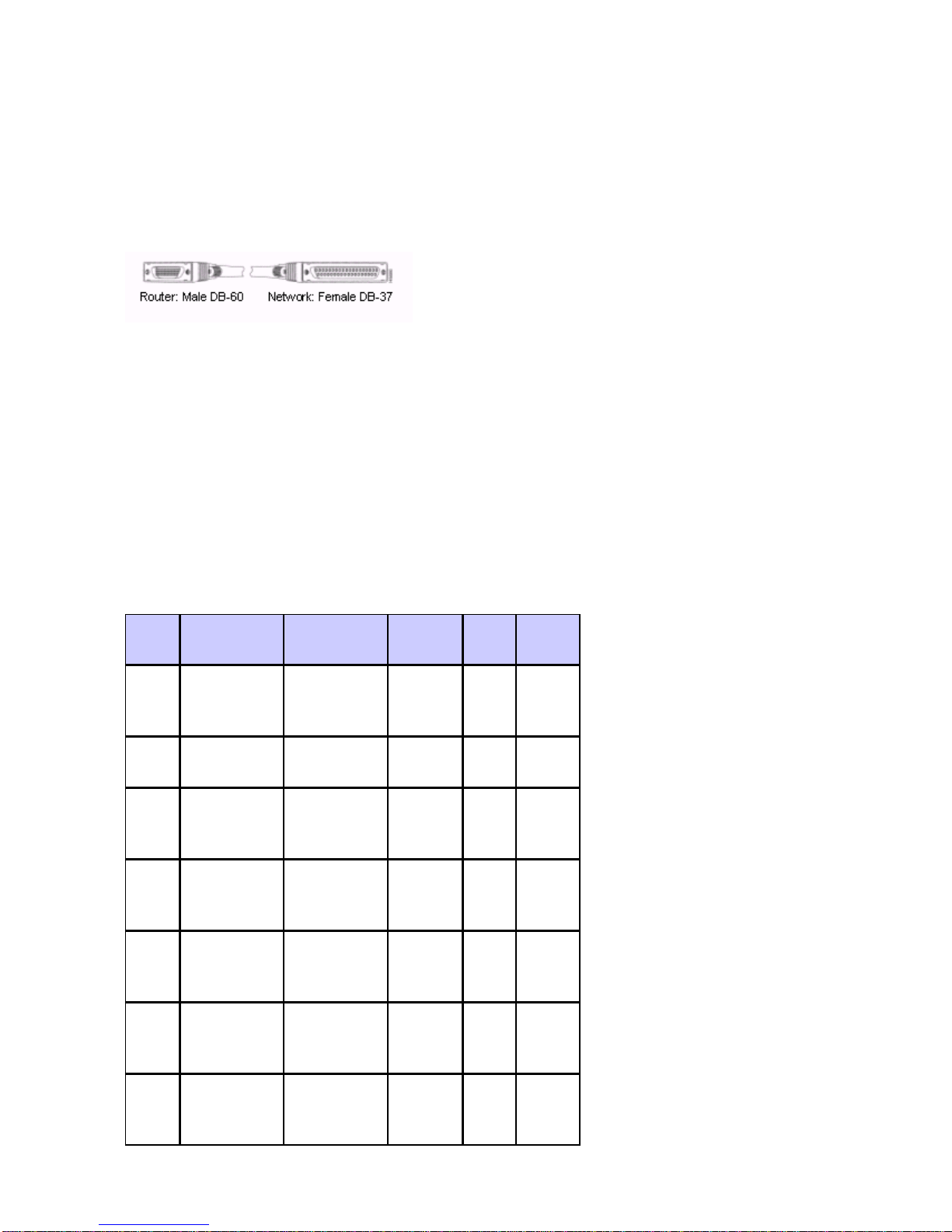
EIA/TIA−449 Serial Cable Assembly
EIA/TIA−449 DTE Cable Pinouts
The table below shows the EIA/TIA−449 DTE cable pinouts (DB−60 to DB−37).
Note: The arrows indicate signal direction:
−−−> indicates DTE to DCE• <−−− indicates DCE to DTE•
Signal Description Direction Signal