Cissell LOWBOYMAN44 Installation guide

Page 1
Remove iron (1), iron rest (2) and
steam hose (3) from carton.
A. Unwind iron cord which is wrapped
around iron handle.
B. Set iron on iron rest.
C. Slip steam hose (3) over iron steam
tube and tighten hose clamp (4).
D. Take steam hose (3) in one hand and
iron cord in other and wrap iron cord
around steam hose at least twelve
times. (see illustration on next page).
E. Press hose cord spring clip (5) around
iron cord to help hold cord in position.
MAN44 3/97
IRON AND LOWBOY ASSEMBLY INSTRUCTIONS
CISSELL MANUFACTURING COMPANY
HEADQUARTERS PHONE: (502) 587-1292
831 SOUTH FIRST ST. SALES FAX: (502) 585-3625
P.O. BOX 32270 SERVICE/PARTS FAX: (502) 681-1275
LOUISVILLE, KY 40232-2270

Page 2
F. Take support spring (6) and connect S
hook to hose support clamp (7) pinch S
hook closed.
G. Connect Low Boy (8) to steam line as
illustrated on following page.
H. Insert support string (6) end into Low
Boy (8) support spring plate and
tighten square head set blot.
I. Slip steam hose (3) over Low Boy (8)
steam tube and tighten hose clamp (4).
J . Connect iron cord (5) to Low Boy (8)
electrical box as illustrated on
following page.

Page 3
Ref. No. Part No. Description
1 J17 S Hook
2 LB7 Support Spring
3 GSB145 Hose Support Clamp
4 J 1 Hose Cord Spring Clip
(3 required)
5 J42 Hose Clamp (2 required)
6 S05 Steam Hose (5 ft.)
7 K382 Cord Assembly
8 PIU23 Iron Rest
9 Steam Electric Iron (See attached)
10 Low Boy (See attached)
OVERALL VIEW PARTS

Page 4
TYPE D LOW BOY ASSEMBLY
FOR CISSELL STEAM-ELECTRIC IRON
WITH ELECTRIC THUMB SWITCH
LB148 Solenoid Lowboy Valve
120V. 50-60 Cy. consists of Ref. No. 1-21
LB149 Solenoid Lowboy Valve
250V. 50-60 Cy. consists of Ref. No. 1-21
Support Rod and Hose Assembly - LB105
Consists of Ref. Nos. 22-27
For Lowboy & Condenser Ass'y Electric Box Assembly
Consists of Ref. Nos. 40-56
LB225 - 120V/50/60
LB226 - 240V/50/60
Ref. No. Part No. Description
1 SV80 ............. 1/4-20 Hex Hd. Scw.
2 LB901........... Nameplate (120/50-60)
LB902........... Nameplate (240/50-60)
3 LB82 ............. Top Cover
4 SV19 ............. Leaf Spring
5 SV137 ........... Flux Washer
6
7 SV54 ............. Tube
8
9 LB231........... Solenoid Coil (120/50-60)
LB232........... Solenoid Coil (240/50-60)
10 LB116 ........... Shield
11 LB83 ............. Bottom Cover
12 SV22 ............. Plunger Casing Assy.
13 SV11 ............. Metal Gasket
14 SVA50 ........... Plunger Assy.
15 SV51 ............. Teflon Seat
16 LB2 ............... Valve Body
17 LB5 ............... Hose Connection
18 V73 ............... Valve Stem Assy.
19 V30 ............... Small Pack Ring
20 V18 ............... Gasket
21 LB118 ........... Cable Assy.
22 LB7 ............... Support Rod
2 3 S 5 .................. 5 Ft. Steam Hose
24 GSB145........ Hose Clamp
25 GSB145........ Hose Clamp
26 J 1 .................. Spring Clip
2 7 J 1 7 ................ S Hook
28 F876 ............. 90° Connector
29 C170 ............. Cable Bushing
30 LB117 ........... Flexible Cable
31 LB56 ............. Spring Support Plate
32 LB48 ............. 1/4 - 20 x 1/2 Set Screw
33 FB188........... 5/16 x 2 Hex Hd. Screw
34 V56 ............... 5/16 - 24 Hex Nut
35 LB13 ............. Chamber Shield
36 LB55 ............. No. 14 x 1 Pan Hd. Screw
37 LB129........... Rating Nameplate
38 LB20 ............. 1/2 x 3 Pipe Nipple
39 SG45 ............. 1/2 Pipe Tee
40 LB30 ............. Switch Cover Plate
41 LB53 ............. Double Pole Switch
42 M102 ............ Amber Light 110V
M454 ............ Amber Light 220V
43 LB221........... Box Welded Asm.
44 LB227........... Terminal Mounting Plate
45 LB222........... Terminal Block
46 LB59 ............. Blank Face Plate
47 LB166........... 6-32 x 1/2 O. H. Screw
48 TU3478 ........ #8-32 x 1/2 S. T. Screw
49 TU3400 ........ #6-32 Hex Nut
50 LB291........... #6-32 x 3/8 Screw
51 M270 ............ #6 I. T. Lockwasher
52 M271 ............ #8 I. T. Lockwasher
53 LB211 ........... Power Conn. Label
54 TU10193 ...... Heyco Bushing
55 TU7414 ........ Cup Washer
56 TU8563 ........ Green Ground Screw
57 TU2714 ........ 1/2 Close Nipple
58 SGC2 ............ Condenser Assy.
59 SGV1 ............ Valve Assy.
60 LB1 ............... Chamber
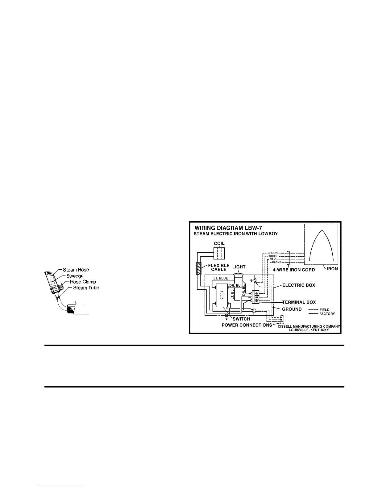
LB224 .......... Wiring (120, 240 V. 50/60 Cy.)
Not Illustrated

Page 5
INSTALLATION
SET UP: Set unit in position and fasten securely to board. Slip support spring in position and fasten with set screw. Fasten iron
rest to board.
IMPORTANT: Before making steam return connections to unit, make steam supply connections. Remove all drain plugs, open
steam supply globe valve to steam-flush any borings, grindings or foreign matter that may be clinging within casting or pipes. Close
globe valve; replace drain plugs and make steam return connections.
Before attaching steam hose from steam-electric iron to solenoid valve, with steam pressure on unit operate thumb switch several
times to remove loose particles of scale dirt, which may become embedded in valve seat. Then fasten steam hose to solenoid valve.
STEAM SUPPLY: Steam supply connection must fall towards machine (without water pockets). Make connection with 12 or more
riser out of steam supply line with union and globe valve. (NOTE: If machine is on the end of a line of equipment, then extend
steam header line at least four feet beyond machine. Install check valve and trap at end of line. If gravity return omit trap.)
STEAM RETURN: If steam is returned to atmosphere or sewer, make steam return connection with union, globe valve, check
valve and trap with drain. If steam is gravity returned to boiler, omit trap, but install trap as close to floor and as near machine as
possible. Inspect traps carefully for inlet and outlet marks and install according to factory instruction. BLOW SCALE AND DIRT
FROM STEAM LINES BEFORE INSTALLING TRAP TO INSURE PROPER OPERATION.)
WIRING: Check Voltage and current of solenoid valve and
see that they correspond with power line before making
installation. Use irons with properly rated thumb switch.
NOTE: Connect power supply to terminals in electric box
as per wiring diagram in accordance with electric code in
your area.
FOR THREE PHASE CURRENT: Connect two wires
from three phase supply to two Power Connections of outlet
box.
IMPORTANT: Connect ground wire as shown and check
all wiring before closing switch.
MECHANICAL SPECIFICATIONS
Boiler Horsepower - Approximately 1/8.
Operating Steam Pressure - 5 to 100 lbs.
Steam Supply - 1/2 Pipe Connection.
Steam Return - 1/2 Pipe Connection.
IMPORTANT
Attach Steam Hose to Steam Tube as
illustrated. Push Steam Hose down on
Steam Tube just far enough beyond
swedge to allow Hose clamp
connection. Do not push Steam Hose
all the way down on Steam Tube as
this will cause hose to burn out.
MECHANICAL OPERATION
Place iron on rest. Turn toggle switch on (pilot light indicates
when current is on); allow iron to heat, set indicator to Rayon
Open steam supply and return valves. A cold iron will throw
water. Wait until iron becomes hot then push electric thumb
switch of iron to allow steam to flow from soleplate of iron.
Release thumb switch to stop steam flow. Screw valve knob in
for less steam, out for more.
MECHANICAL MAINTENANCE
To replace coil in solenoid valve, remove bolt, cover, leaf spring,
insulating washer and coil. Install new coil and replace washer,
spring, cover and bolt. Solenoid valve is packless. To replace
renewable valve seat or plunger, unscrew large hex nut from
lower cast body. Coil or solenoid valve is constructed of heat
resisting materials. When ordering new coil, specify voltage
and current, giving frequency of power line. Example: 120
Volt, 60 cycle, A.C.

Page 6
CISSELL LOW BOY ASSEMBLY
FOR CISSELL STEAM-ELECTRIC IRON
WITH ELECTRIC THUMB SWITCH
Table of contents
Other Cissell Iron manuals