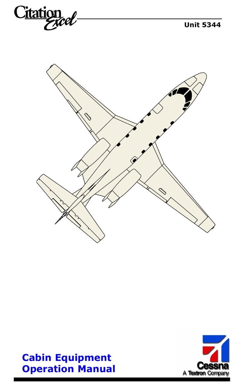
Citation Encore 560 User manual

OperatingManual
Member of GAMA
COPYRIGHT
”
2000
CESSNA AIRCRAFT COMPANY
WICHITA, KANSAS, USA
56OMB-01
MODEL 560
560-0539 THRU -5000
28 SEPTEMBER 2000
REVISION 1 3 NOVEMBER 2005


LOG OF EFFECTIVE PAGES
MODEL 560
LOG OF EFFECTIVE PAGES
Use this page to determine the currency and applicability of your Operating Manual. Pages affected by the
current revision are indicated by an asterisk (*) preceding the pages listed under the Page column.
Determine which pages are applicable to your airplane by checking effectivity of each page, which is listed
after each page entry where an airplane serialization is required. Only the pages applicable to your airplane
should be retained in the Operating Manual. This manual pertains to Model 560 Encore airplanes, serial
numbers 560-0539 thru -5000.
In addition to the serialization shown on the effectivity pages, pages that apply to certain airplanes have the
applicable airplane configuration code on the bottom of the pages. Pages not serialized apply to all
airplanes.
Refer to page Introduction-3 for an explanation of airplane configuration codes.
Following is a description of the Log of Effective Pages columns:
Revision Number - Indicates the revision number of the applicable manual.
Date - Indicates the date on which the manual (or revision to the manual) was issued.
Page - Describes the page (or pages) in question. Page numbers with a slash (/) indicates text or
illustration on the first page and a blank backup on the second page.
Rev Level - Indicates the revision level of the page (or pages).
REVISION REVISION
NUMBER DATE NUMBER DATE
Original . . . . . . . 0 . . . . . 28 September 2000 Revision . . . 1 . . . 3 November 2005
PAGE REV PAGE REV
NUMBER LEVEL NUMBER LEVEL
*Title . . . . . . . . . . . . . . . . . . . . . . . . 1 * 7-1/7-2 . . . . . . . . . . . . . . . . 1
*Effectivity-1/Effectivity-2 . . . . . . . . . . 1 * 7-3 thru 7-108 . . . . . . . . . . . 1
*Introduction-1/Introduction-2 * 7-109/7-110 . . . . . . . . . . . . 1
*Introduction-3 thru Introduction-22 . . 1 * 7-111/7-112 . . . . . . . . . . . . 1
*Introduction-23/Introduction-24 . . . . 1
*. . . . . . . . . . . . . . . . . . . . . . . . . . . . * Index-1 thru Index-6 . . . . . . . 1
*1-1 thru 1-2 . . . . . . . . . . . . . . . . . . 1
*1-3 thru 1-22 . . . . . . . . . . . . . . . . . 1
*
*2-1 thru 2-2 . . . . . . . . . . . . . . . . . . 1
*2-3 thru 2-68 . . . . . . . . . . . . . . . . . 1
*3-1 thru 3-2 . . . . . . . . . . . . . . . . . . 1
*3-3 thru 3-74 . . . . . . . . . . . . . . . . . 1
*4-1/4-2 . . . . . . . . . . . . . . . . . . . . . . 1
*4-3 thru 3-40 . . . . . . . . . . . . . . . . . 1
*5-1 thru 5-2 . . . . . . . . . . . . . . . . . . 1
*5-3/5-4 . . . . . . . . . . . . . . . . . . . . . . 1
*5-1 thru 5-36 . . . . . . . . . . . . . . . . . 1
*6-1/6-2 . . . . . . . . . . . . . . . . . . . . . . 1
*6-3 thru 6-27 . . . . . . . . . . . . . . . . . 1
I
56OMB-01 Configuration AA Effectivity-1/Effectivity-2(Blank)


MODEL 560 INTRODUCTION
CONTENTS
SECTION
INTRODUCTION . . . . . . . . . . . . . . . . . . . . . . . . . . . . . . . . . . INTRODUCTION-1
DESCRIPTION AND SPECIFICATIONS . . . . . . . . . . . . . . . . . . . . . . . . . . . . . . . 1
AIRPLANE AND SYSTEMS . . . . . . . . . . . . . . . . . . . . . . . . . . . . . . . . . . . . . . . . 2
INSTRUMENTATION AND AVIONICS . . . . . . . . . . . . . . . . . . . . . . . . . . . . . . . . 3
OPERATING INFORMATION . . . . . . . . . . . . . . . . . . . . . . . . . . . . . . . . . . . . . . . 4
ABNORMAL PROCEDURES . . . . . . . . . . . . . . . . . . . . . . . . . . . . . . . . . . . . . . . 5
EMERGENCY PROCEDURES . . . . . . . . . . . . . . . . . . . . . . . . . . . . . . . . . . . . . . 6
FLIGHT PLANNING AND PERFORMANCE . . . . . . . . . . . . . . . . . . . . . . . . . . . . 7
INDEX . . . . . . . . . . . . . . . . . . . . . . . . . . . . . . . . . . . . . . . . . . . . . . . . . . INDEX-1
I
56OMB-01 Configuration AA Introduction-1/Introduction-2(Blank)


INTRODUCTION
MODEL 560
INTRODUCTION
UNIT AND SERIAL NUMBER
On all Model 560 Citation Encore airplanes, the serial and unit number are stamped into the airplane
identification nameplate. This manual uses serial numbers to describe airplane effectivities.
OPERATING MANUAL PART NUMBER
Each page in the Operating Manual contains the part number of the manual and the page status of
each page; Refer to the following example:
AIRPLANE CONFIGURATION CODES
The following is a list of airplane configuration codes which appear at the bottom of the page of the
Operating Manual, and which indicates page effectivity by serial number. Pages marked AA apply to all
airplanes. This list contains only the configurations which have been incorporated into this Operating
Manual. Configuration Effectivity by
Code Serial Number
AA Airplanes 560-0539 thru -5000.
AB Airplanes 560-0539 thru -0625 not incorporating
SB560-77-04.
AC Airplanes 560-0539 thru -0625 incorporating SB560-
77-04, and Airplanes 560-0626 thru -5000.
AD Airplanes 560-0539 thru -0643 not incorporating
SB560-34-103.
AE Airplanes 560-0539 thru -0643 incorporating SB560-
34-103, and Airplanes 560-0644 thru -5000.
AF Airplanes 560-0539 thru -0651 not incorporating
SB560-23-32.
AG Airplanes 560-0539 thru -0651 incorporating SB560-
23-32, and Airplanes 560-0652 thru -5000.
(Continued Next Page)
Operating Manual
56 OMB - 00
Page Status (Original)
Manual (Operating Manual, Airplanes 560-0539 thru -5000)
Airplane Model (560)
I
56OMB-01 Configuration AA Introduction-3

INTRODUCTION MODEL 560
AIRPLANE CONFIGURATION CODES (Continued)
Configuration Effectivity by
Code Serial Number
AH Airplanes 560-0626 thru -0644 not incorporating
SB560-77-06.
AI Airplanes 560-0645 thru -0677 not incorporating
SB560-77-06.
AJ Airplanes 560-0626 thru -0651 incorporating SB560-
77-05, and Airplanes 560-0652 thru -5000.
AK Airplanes 560-0626 thru -0651 not incorporating
SB560-77-05.
AL Airplanes 560-0539 thru -0648 not incorporating
SB560-28-11.
AM Airplanes 560-0539 thru -0648 incorporating SB560-
28-11 and Airplanes 560-0649 thru -5000.
AN Airplanes 560-0539 thru -0631.
AO Airplanes 560-0632 thru -5000.
AR Airplanes 560-0626 thru -0677 incorporating SB560-
77-06 and Airplanes 560-0678 thru -5000.
I
Introduction-4 Configuration AA 56OMB-01

INTRODUCTION
MODEL 560
COVERAGE
This manual is intended to provide an information source for familiarization, review and suggested
technique to achieve maximum safety, passenger comfort and utility, and is based on experience gained in
the typical transport category jet operating environment.
While the Operating Manual covers and expands upon the basic FAA Approved Airplane Flight Manual
information, the FAA approved document shall take precedence should a difference be noted.
REVISIONS
As new information becomes available, the Operating Manual will be revised. Throughout this manual,
revised material is identified by use of change bars or pointing hands.
TEXT CHANGES
In The Main Body
A change bar located in the left margin adjacent to the applicable text will extend the full length of new
material on new pages. On presently existing pages, a change bar will extend the length of new or
revised text. Deleted text will be indicated with a change bar near the beginning of its previous
location.
In Footers
A change bar in the footer will indicate one of the following conditions:
• A configuration code change.
• Unedited text has slid on or off of the page.
• There is slippage of text as well as a change in text on the same page (in this case, a change
bar would appear adjacent to the edited text and in the footer).
ILLUSTRATION CHANGES
A pointing hand or a change bar may be used to indicate changes to an existing illustration.
If changes are minor, a change bar or pointing hand will appear adjacent to the changed portion of the
illustration. If changes are extensive, a pointing hand or change bar will appear adjacent to the figure
number. New figures will use only a pointing hand adjacent to the figure number.
SERVICE BULLETIN CONFIGURATION LIST
Airplane Serial Revision Incorporated
Number Title Effectivity Incorporated In Airplane
SB560-23-32 Communications - 560-0539 thru -0651
RNZ-850 Navigation
Radio Upgrade
SB560-34-103 Navigation - GH-3000 560-0539 thru -0643
Field Replacement
SB560-77-04 AMLCD Modification 560-0539 thru -0625
SB560-77-05 AMLCD Emergency
Lighting Modification 560-0626 thru -0651
SB560-28-11 Fuel - Encore Fuel Boost 560-0539 thru -0648
Pump Wire Routing
Improvement
SB560-77-06 Engine Indicating - 560-0626 thru -0677
Active Matrix Liquid
Crystal Display (AMLCD)
Upgrade
I
56OMB-01 Configuration AA Introduction-5

INTRODUCTION MODEL 560
DEFINITIONS AND ABBREVIATIONS
AC: Alternating Current
Accelerate-Stop Distance: The distance required to accelerate the aircraft and then abort the
takeoff due to a failed engine, or other emergency, occurring just
prior to V
1with brake application commencing at V1
ADF: Automatic Direction Finding
ADI: Attitude Director Indicator
AIA: Anti-icing Additive
Altitude: All altitudes used in this manual are pressure altitudes unless
otherwise stated.
AM or AME: Amplitude Modulation
Anti-Ice/Deice Systems: The following systems comprise the anti-ice/deice systems:
a. Windshield Bleed Air Anti-Ice.
b. Wing Bleed Air Anti-Ice.
c. Engine Bleed Air Anti-Ice.
d. Pitot-Static System Anti-Ice (includes electrical anti-ice for AOA
vane).
e. Horizontal Stabilizer Pneumatic Deice.
Performance, when referred to ANTI-ICE ON, is based on the wing
and engine anti-ice systems being operated at the same time.
ARM: The horizontal distance from the reference datum to the center-of-
gravity (C.G.) of an item.
ATC: Air Traffic Control
Basic Empty Weight: Standard empty weight plus installed optional equipment.
°C: Temperature in degrees Celsius.
CAT II: Category II Operation. A straight-in ILS approach to the runway of
an airport under a Category II ILS instrument approach procedure.
CB: Circuit Breaker
CDI: Course Deviation Indicator
Center-of-Gravity (C.G.): The point at which an airplane would balance if suspended.
C.G. Arm: The arm obtained by adding the airplane’s individual moments and
dividing the sum by the total weight.
C.G. Limits: The extreme center-of-gravity locations within which the airplane
must be operated at a given weight.
Climb Gradient: The ratio of the change in height during a portion of a climb, to the
horizontal distance traversed in the same time interval.
DC: Direct Current
I
Introduction-6 Configuration AA 56OMB-01

INTRODUCTION
MODEL 560
Demonstrated Crosswind: The demonstrated crosswind velocity of 30 knots (measured at 30
feet above the runway surface) is the velocity of the crosswind
component for which adequate control of the airplane during takeoff
and landing was actually demonstrated during certification tests.
This is not limiting. The demonstrated crosswind velocity for an
airplane using thrust reversers is 30 knots.
DG: Directional Gyro
DH: Decision Height
DME: Distance Measuring Equipment
Engine Cycle: Any operational sequence involving engine start, power to 80
percent N1or above and engine shutdown.
Engine Out Accelerate-Go The
horizontal distance from brake release to the point where the
Distance airplane attains a height of 35 feet above the runway surface on a
takeoff during which an engine is recognized to have failed at V
1
and the takeoff is continued.
°F: Temperature in degrees Fahrenheit
FAA: Federal Aviation Administration
Flameout: Unintentional loss of engine during operation.
FM: Frequency Modulation
G: Acceleration due to gravity. One G equals the pull of gravity with
no acceleration.
Gross Climb Gradient: The climb gradient that the airplane can actually achieve with ideal
ambient conditions (smooth air).
HF: High Frequency
Hot Start: An engine start, or attempted start, which results in an interstage
turbine temperature exceeding 550°C or which otherwise exceeds
the engine starting temperature envelope limits.
Hr: Hour
HSI: Horizontal Situation Indicator
Hz: Hertz
In. Hg: Inches of Mercury
IOAT: The indicated outside air temperature as read from the pilot’s panel.
It is the same as RAT.
IFR: Instrument Flight Rules
I
56OMB-01 Configuration AA Introduction-7

INTRODUCTION MODEL 560
ISA: International Standard Atmosphere in which:
a. The air is a dry perfect gas;
b. The temperature at sea level is 15°C (59°F);
c. The pressure at sea level (standard datum plane) is 29.92
inches Hg. (1013.2 Mb);
d. The temperature gradient from sea level to the altitude at
which the temperature is -56.6°C will be -1.98°C per 1000
feet.
ITT: Interstage Turbine Temperature. Engine operating temperature
taken between the high and low pressure turbine sections.
Jack Point: One of three points on the airplane designed to rest on a jack.
KCAS: Indicated airspeed (knots) corrected for position error (instrument
error is assumed to be zero).
kHz: Kilohertz
KIAS: Airspeed
indicator
reading
(knots). Zero instrument error is
assumed.
KTAS: True airspeed expressed in knots
Landing Distance: The distance from a point 50 feet above the runway surface to the
point at which the airplane would come to a full stop on the runway.
Lb: Pound
Lb/hr: Pounds-per-hour
LH: Left Hand
LSB: Lower Side Band
M or Mach: Mach Number. The ratio of true airspeed to the speed of sound.
MAC: Mean Aerodynamic Chord. The chord of an imaginary airfoil which,
throughout the flight range, will have the same force vectors as
those of the wing.
Maximum Brake Energy Speed: The maximum speed from which a stop can be accomplished within
the energy capabilities of the brakes.
Maximum Continuous Power: The power developed at 700°C ITT or 100.0 percent N1RPM,
which is the maximum power setting without a time limit. Used in
emergency conditions only.
Maximum Cruise Thrust Setting Maximum power setting recommended for cruise thrust.
Maximum Landing Weight: Maximum weight approved for landing touchdown.
Maximum Ramp Weight: Maximum weight approved for ground maneuver. It includes engine
start and taxi fuel.
Maximum Zero Fuel Weight: Maximum weight exclusive of usable fuel.
Mb: Millibars
Moment: The product of the weight of an item multiplied by its arm.
(Moment divided by a constant is used to simplify balance
calculations by reducing the number of digits.)
I
Introduction-8 Configuration AA 56OMB-01

INTRODUCTION
MODEL 560
MHz: Megahertz
Multiengine Normal Climb Maximum power setting recommended for normal multiengine
Thrust Setting climb.
N1: Low pressure turbine speed. The fan is attached to the low
pressure turbine.
N2: High pressure turbine speed.
Net Climb Gradient: The gross climb gradient reduced by 0.8 percent during the takeoff
phase and 1.1 percent during enroute. This conservatism is
required by FAR Part 25 for terrain clearance determination to
account for variables encountered in service.
OAT or TEMP: Outside Air Temperature or Ambient Air Temperature. The free air
static temperature, obtained either from ground meteorological
sources or from inflight temperature indications adjusted for
instrument error and compressibility effects.
Payload: Weight of occupants, cargo and baggage.
Position Correction: A correction applied to indicated airspeed or altitude to eliminate
the effect of the location of the static pressure source on the
instrument reading. No position corrections are required when using
performance section charts in Section VII since all airspeeds and
altitudes in this section are presented as "indicated" values except
for stall speeds which are presented as "calibrated" values.
Power Lever: Engine power control; synonymous with throttle in same
terminology.
Pressure Altitude: Altitude measured from standard sea level pressure (29.92 inches
Hg) (standard datum plane) by a pressure or barometric altimeter.
It is the indicated pressure altitude corrected for position and
instrument error. In this manual, altimeter instrument errors are
assumed to be zero.
PSI: Pounds-per-Square Inch
PSIG: Pounds-per-Square Inch Gage
RAT: Ram Air Temperature. The indicated outside air temperature as
read from the pilot’s instrument panel.
REF: Reference
Reference Datum: An imaginary vertical plane from which all horizontal distances are
measured for center-of-gravity purposes. In the Model 560, the
zero reference datum line is 93.70 inches forward of the jig point
(airplane nose jack pad location).
Reference Zero: The point in the takeoff flight path at which the airplane is 35 feet
above the takeoff surface and at the end of the takeoff distance
required.
Residual Fuel: The undrainable fuel remaining when the airplane is defueled in a
specific attitude by the normal means and procedures specified for
draining the tanks.
I
56OMB-01 Configuration AA Introduction-9

INTRODUCTION MODEL 560
Residual Ice: That ice which is not completely removed from the leading edge of
the wing and horizontal stabilizer by the surface anti-ice/deice
system during operation in icing conditions. Refer to Sections II
and IV of the airplane flight manual for applicable procedures.
Reverse Thrust: The thrust produced when the thrust reverser deflectors are
deployed into the engine exhaust stream.
RH: Right Hand
RMI: Radio Magnetic Indicator
RNAV: Area Navigation
RPM: Revolutions-per-Minute.
R/T: Receiver Transmitter
SAT: Static Air Temperature. The temperature of the air undisturbed by
the presence or motion of the airplane. SAT and OAT are similar
terms.
SSB: Single Side Band
Standard Empty Weight: Weight of a standard airplane including unusable fuel, full oil and full
operating fluids.
Station: A location along the airplane fuselage given in terms of distance
from the reference datum plane.
Takeoff Field Length: The Takeoff Field Length given for each combination of gross
weight, ambient temperature, altitude, wind and runway gradients is
the greatest of the following:
a. 115 percent of the two-engine horizontal takeoff distance from
start to a height of 35 feet above runway surface.
b. Accelerate-stop distance.
c. The engine-out accelerate-go distance.
No specific identification is made on the charts as to which of these
distances governs a specific case. In all cases considered by the
charts, the field length is governed by either b. or c., as the
factored two-engine takeoff distance is always shorter.
Takeoff Power: Power setting used for takeoff, limited to 5 minutes duration, not to
exceed 720°C ITT or 100.0 percent N1RPM.
TAS: True Airspeed. The airspeed relative to undisturbed air which is the
CAS corrected for altitude, temperature and compressibility factor.
TAT: Total Air Temperature. Air which has had its temperature increased
due to adiabatic compression caused by the speed of the airplane.
TAT and RAT are similar terms.
Temperature Compressibility Effects: An error in the indication of temperature caused by airflow over the
temperature probe. The error varies depending on altitude and
airspeed.
Tower Wind: Wind
reported
by the tower or from an FAA source, usually
measured at a height of 30 feet above the runway, used for
computation of takeoff and landing data.
I
Introduction-10 Configuration AA 56OMB-01

INTRODUCTION
MODEL 560
True Airspeed (KTAS): The airspeed (knots) of an airplane relative to undisturbed air.
UHF: Ultra High Frequency
Unusable Fuel: Fuel remaining after fuel runout tests have been completed in
accordance with governmental regulations.
U.S.: United States
Usable Fuel: Fuel available for flight planning.
USB: Upper Side Band
V1: Takeoff decision speed. The distance to continue the takeoff to 35
feet will not exceed the scheduled takeoff field length if recognition
occurred at V1(accelerate-go). The distance to bring the airplane
to a full stop (accelerate-stop) will not exceed the scheduled takeoff
field length provided that the brakes are applied at V1.
V2: Takeoff safety speed. This climb speed is the actual speed at 35
feet above the runway surface as demonstrated in flight during
takeoff with one engine inoperative.
V35: This climb speed is the actual speed at 35 feet above the runway
surface as demonstrated in flight during takeoff with both engines
operating.
VA: The maneuvering speed is the maximum speed at which application
of full available aerodynamic control will not overstress the airplane.
VAPP: The landing approach airspeed (1.3 VS1) with 15-degree flap
position, landing gear UP.
VENR: Single-engine enroute climb speed.
VFE: Maximum flap extended speed. The highest speed permissible with
wing flaps in a prescribed extended position.
VLE: Maximum landing gear extended speed. The maximum speed at
which an airplane can safely be flown with the landing gear
extended.
VLO: Maximum landing gear operating speed. The maximum speed at
which the landing gear can be safely extended or retracted. The
Model 560 has different VL0 speeds for extension and retraction.
VMCA: Minimum airspeed in flight at which directional control can be
maintained, when one engine is suddenly made inoperative. VMC
A
is a function of engine thrust which varies with altitude and
temperature. The VMCA presented in Section I was determined for
maximum thrust. VMCA = 86 KIAS.
VMCG: Minimum airspeed on the ground at which directional control can be
maintained, when one engine is suddenly made inoperative, using
only aerodynamic controls. VMCG is a function of engine thrust
which varies with altitude and temperature. The VMC
G
presented in
Section I was determined for maximum thrust.
7° Flaps, VMCG = 96 KIAS.
15° Flaps, VMCG = 92 KIAS.
VMCL: Minimum airspeed in the air, in the landing configuration, at which
directional control can be maintained, when one engine is suddenly
made inoperative. VMCL is a function of engine thrust which varies
with altitude and temperature. The VMCL is 88 KIAS at maximum
takeoff thrust.
I
56OMB-01 Configuration AA Introduction-11

INTRODUCTION MODEL 560
VR: The rotation speed is the speed at which rotation is initiated during
takeoff to attain the V2climb speed at or before a height of 35 feet
above runway surface has been reached.
VREF: The landing approach airspeed at the 50-foot point with flaps in
landing position and landing gear extended (1.3 VSO).
VSO: The stalling speed in the landing configuration.
VS1: The stalling speed obtained in a specified configuration.
VY: Best Rate-of-Climb Speed. The airspeed which delivers the
greatest gain of altitude in the shortest possible time.
VYSE: Best
Single-Engine
Rate-of-Climb
Speed.
The
airspeed
which
delivers the greatest gain of altitude in the shortest possible time
with one engine operating.
VMCL: Minimum airspeed in the air, in the landing configuration, at which
directional control can be maintained, when one engine is suddenly
made inoperative. VMCL is a function of engine thrust which varies
with altitude and temperature. The VMCL is 92 KIAS at maximum
takeoff thrust.
VMO/MMO: Maximum Operating Limit Speed is the calibrated speed limit that
may not be deliberately exceeded in normal flight operations. V is
expressed in knots and M in Mach number.
VX: Best Angle-of-Climb Speed.
The airspeed which delivers the
greatest gain of altitude in the shortest possible horizontal distance.
VA: Volt Amperes
VAC: Volts Alternating Current
VG: Vertical Gyro
VHF: Very High Frequency
VLF: Very Low Frequency
VNAV: Vertical Navigation
VOR: Very High Frequency Omnidirectional Radio Range
VOT: Very High Frequency Omnidirectional Test
Visible Moisture: Visible moisture includes, but is not limited to the following
conditions: fog or clouds with visibility less than 1 mile, wet snow
and rain.
Wind: The wind velocities recorded as variables on the charts of this
manual are to be understood to refer to the headwind or tailwind
components of the actual winds at 30 feet above the runway
surface (tower winds).
Windmill: Engine turbine rotation from airstream inputs.
WPT: Waypoint
I
Introduction-12 Configuration AA 56OMB-01

INTRODUCTION
MODEL 560
STANDARD SYSTEM SYMBOLS
Standard System Symbols have been developed and utilized in illustrated system diagrams throughout
the Operating Manual. Included are symbols for components within the hydraulic/pneumatic systems, fuel
system, bleed air, deice and vacuum systems and oxygen systems.
Symbols utilized in electrical schematics follow the Standard System Symbols.
HYDRAULIC/PNEUMATIC SYSTEM SYMBOLS
HYDRAULIC PUMP
ENGINE DRIVEN OR
ELECTRIC MOTOR
DRIVEN
PNEUMATIC RESERVOIR
(BOTTLE) WITH
PRESSURE GAGE
FLOW
REGULATOR
FILTER WITH
BYPASS
HYDROPNEUMATIC
ACCUMULATOR WITH
PRESSURE GAGE
I
56OMB-01 Configuration AA Introduction-13

INTRODUCTION MODEL 560
HYDRAULIC/PNEUMATIC SYSTEM SYMBOLS (Continued)
PRESSURE SWITCH
RESTRICTOR
GROUND SERVICE, EXTERNAL
QUICK DISCONNECTS
SHUTOFF VALVE WITH
PRESSURE RELIEF
TWO-POSITION - 2-WAY
(MOTOR ACTUATED)
SHUTOFF VALVE WITH
TWO-POSITION - 2-WAY
(MANUALLY ACTUATED)
SHUTOFF VALVE
TWO-POSITION - 2-WAY
(PRESSURE OPERATED)
SHUTOFF VALVE
TWO-POSITION - 2-WAY
(SOLENOID OPERATED)
VALVE
TWO-POSITION - 3-WAY
(SOLENOID OPERATED)
I
Introduction-14 Configuration AA 56OMB-01

INTRODUCTION
MODEL 560
HYDRAULIC/PNEUMATIC SYSTEM SYMBOLS (Continued)
SHUTTLE VALVE
CHECK VALVE
LANDING GEAR CONTROL
MODULE MANIFOLD VALVE
THREE-POSITION - 4-WAY
(SOLENOID OPERATED)
VALVE
TWO-POSITION - 2-WAY
(MOTOR (M) DRIVEN)
VALVE
TWO-POSITION - 2 - WAY
(MECHANICALLY ACTUATED)
ACTUATOR
I
56OMB-01 Configuration AA Introduction-15

INTRODUCTION MODEL 560
FUEL SYSTEM SYMBOLS
PUMP
(EJECTOR)
PUMP
(FUEL PRESSURE (FP) DRIVEN)
PUMP
(DC MOTOR (DCM) DRIVEN)
PUMP
(ENGINE DRIVEN (ED))
FLOAT SWITCH
FILTER WITH
BYPASS RELIEF VALVE
SHUTOFF VALVE - NORMAL OPEN
(THERMAL RELIEF (TR) -
DC MOTOR (DCM) DRIVEN)
I
Introduction-16 Configuration AA 56OMB-01
Table of contents
Popular Aircraft manuals by other brands

Diamond
Diamond DA20-C1 Flight manual
Schempp-Hirth
Schempp-Hirth Ventus-3M Performance Preliminary Flight Manual

Diamond
Diamond DA 42 Flight manual

Remos
Remos GX Pilot operating handbook
Air Creation
Air Creation GTE Trek 503 Instruction and maintenance manual

Diamond Aircraft
Diamond Aircraft DA20-A1 Maintenance manual

Piper Aircraft Corporation
Piper Aircraft Corporation ARCHER II PA-28-181 Operating handbook

Lone Star Aviation
Lone Star Aviation KMD-150 instruction sheet

Raytheon
Raytheon BEECH BARON 58P Maintenance manual

Eclipse
Eclipse 550 Maintenance manual

Shark
Shark UL Flight manual

Cessna
Cessna 172R Operating handbook
