AEROPRAKT AEROPRAKT-22L2 Owner's manual

Aeroprakt
Ltd.
24,
Polevaya
str., Kiev,
Ukraine
Tel: 0038 044
496-77-21
Fax: 0038 044
496-77-31
e-mail: air@prakt.kiev.ua
www
.aeroprakt.kiev
.ua
AEROPRAKT-22L2
Pilot Operating
Handbook
A22L2-POH-02
This
manual
must be
carried
in the
airplane
at all
times


AEROPRAK
T
-
22L2 Pilot
Operating
Handbook
A22L2
-
POH
-
02
Model: AEROPRAKT-22L2
(
A-22L2
)
Serial No:
484
Registration:
Document No:
A22L2-POH-02
Date of issue:
20.08.2015
Approved by:
Yuriy Yakovlyev
Signature:
Position:
Chief
Designer
Stamp:
Date of
approval:
20.08.2015
This
airplane
is to be
operated
in
compliancewith information
and
limitations contained herein.
2

A22L
2
-
POH
-
02
AEROPRAKT
-
22L2
Pilot
Operating
Handbook
4
Table of
contents
1 General information
.....................................................................................................
7
1
.
1
Genera
l
........................
..
.
.
........
..
.
.......
.
..
.
.
.
.
..
.
.
..
....
.
.
.......
..
.
..................
...
.
.
..
.
.
.
..........
..
7
1.2 Technical data
..
...........
..
.
...
.
.....
.
..
.
..
:
.
.
...
..
.
.
...
........
..
.....
..
....
.
......
..
.
..
..
..
.
..
.
.
.....
.....
.....
..
.
7
1.3
Airplane three-view drawing ...
..
.
.
.....
....
.
..
.
..
........
.
...
...
..
.....
...
.
..
.
......
...
...
..
........
.
.......
.
.
7
2 Airplane and Systems Descriptions
...........................................................................
8
2.1 Airframe
..
....
.
..
.
........................
..
.
...
..
...
.
...
.
..
.
..
....
...
.....
....
..
..
.
...................
..
.
..........
......
8
2.2 Landing
gear...................................................
...
.....
.....
.
....
.
...
...
.
....
.....
.
..
.
.
..
.
......
..
..... 9
2.3 Engine and its controls
..
.
..............
......
..
.........
.
.........
..
.
.
..
..........
..
.
...
..
..
.
..........
..
....
.
.
..
9
2.4 Propeller
.................................................................................................................
9
2.5 Fuel system
...
.....
...
..
.....
.
....
..
...
........
...
..
..
.
..
.
.
.
.
.....
.
.
....
...
...
.
.............
...
.
..
...
................
10
2.6
Airplane control system
s
.
....
.
.......
.
.
..
...
.
...
..
.
.
.....
.
.
.
.
.
...
..
.
.
.
..
.................
.
...
.
.....
....
.
....
...
11
2.7
Instrument
panel
............
...
...
....
....
.
........
...
.
..
...
...
..
.....
.
.
..
......
.
...........
....
.
.....
.
..
......
.
...
17
2.8 Electric system
.
.............
....
.
.
.
....
.
.....
.
.
.
.
...
.
.....
............
...
...
.........
.......
.....
...
....
...
.
.
......
19
2.9 Seats and harness belts
..
..
..
......
.......
......
..
.
...
...
.......
..
...
..
....
.
..
..
...........
.
.
.
.
...
.
.
..
..
..
....
24
2.10 Cockpit
doors.......................
.
....
...
............
.
.
.
...
..
..
....
....
.
..
..
.......
..
..
....
..
.
.
.
.
.
............
...
.
24
2.11 Baggage container
...................
....
....
......
.
.
.
.
.
..
.
........
...
.
.........
.
...
....
..
..
....
.
.
....
.
..
..
......
24
2.12 Recovery system .......................
.
...
........
..............
..
.......
..
..
............
..
..
..
...
.
.
.
..
..
.
..
..
...
25
3 Operating Limitations
................................................................................................
26
3.1
General.
...........
....
.
..
..
...
.
.
.
....
..
..
...
...
...
..
..
..
.
...
...
....
...
.
.....
............
..
.
..
...
..
......
..
.
..
.
..
..
...
..
26
3.2 Airspeed ...
.
.................
.....
.
..............
.............
..
..
..
.
..
..........
...
..
.
..
.....
..
..
..
...
.......
.
..
...
..
.
26
3.3 Crosswind
limitation.
.
.....
..
............
.
..
...
..
..
...
..
.
......
.
....
.
......
............
.
....
....
.
....
.....
.
.
.
.
..
..
26
3.4 Service ceiling
.......
....
..
...
....
....
.
.
...
...
...
..
..
..
..
..
.
..
....
....
..
.....
...
.
....
.
..
.
..........
.
..
.
..
.
..
.
...
...
.
26
3.5
Maneuvering load factors .....
.
.
.
..
.
.....
.......
..
...............
....
.
..
..
.
..
.
.
....
.........
.
.....
.
.
..
..
...
..
.
26
3.6 Prohibited
maneuvers....
....
.......
.
..
..
............................
.
....
..
..
...
.
..
...
..
..
..
.
.
..
.
.
..
.......
...
.
27
3.7 Operating weights and loading
..
.............
..
..
....
...
..
..............
..
.
.
.
..
...
..
.....
.
.
..
....
.
....
.
..
..
27
3.8 Engine
.
...
.........
...
.........
...
.....
.
.......
.
...
........
..
.
.
.....
..
.
.
.
.
.
..
..
.
....
.......
...
..
.
.....
.
..
.
..
..
.
.
.....
.
..
27
4 Weight and balance
................................................................................................... 29
4.1
General.
..............
...
........
..
.......
.
.
....
.
..
....
.
...
..
.
..
..
......
.....
..
..
...
............
..
.
...
..
...
.
.
.....
.....
.
29
4.2 Actual empty airplane weight and CG position
....
....
.
..
...
..
........
...
....
....
.
..
.
..
...
....
..
..
.
29
4.3 Computation of the CG position before
flight..
.
..
.
..
...
..
...
.
.....
.
........
....
.
.
.
..
.
.
..........
.
...
29
5 Performance
...............................................................................................................
31
5.1
General
.
.......
....
...............
.
.
...
.
.
....
..
...
.
.........
.
..
.
..
.
.
.....
...
..
..
.....
.....
.
...
...
..
..
.
....
.
....
..
....
.
.
.
31
5.2
Takeoff and landing distances
..
..
...........
.
.
.
.
.
..
.
..
...
.....
....
..
..
...
...
....
..........
.
.
.
...
..
.
...
..
..
.
31
5.3
Climb performance
..........
.
.
....
...
..
.
..
..
......
.
.
.
...
...
..
..........
.
.
..
..
...
...
.
.
........
.
..
.
....
.
..
.
..
......
31
5.4 Level flight at cruising speed ........
..
......
..
..
.
.............
...
.
..
....
....
...
.
..
..
...
.
..
.
.
..
.
.
..
.....
..
..
.
31
5.5 Endurance
.............
..
....
....
..
....
.
.
...........
...
.
...................
.
...................
..
.
..
.
.
...........
..
...
31
5.6 "Bug"
effect
......................................
......
..
.
.
..
...
..
.
.....
..
..
.
.
......
.
..
..
.
..
...
..........
.
..
.
.
........
31
6 Emergency procedures
............................................................................................. 32
6.1
Genera
l
..
..
..
.
.....
.
...
.
....
.
.
.
..
.
.
.......
.
...
.
...
..
...
.....
...........
....
..
...
..
.
........
.................
.
.
..........
32
6.2
Engine
failure
......
.
..
.
........
.
...............
....
.
..........
..
.
..............
........
.
...
..
..
.....
.
.....
...
..
..
..
..
32
6.3 Glide ......
..
.....
......
.
......
....
.
..
.
..
...
....
.......
..
...
..
.
.
.....
.
.........
.
..
.......
.
..
....
.
..
....
.
..
.
..........
..
..
.
32
6.4 Restarting engine in flight ...........
.
.
.
............
.
.....
.
.
...
....
.
...
...................
.....
.
.......
.
....
..
.
33
6.5 Emergency landing
........
..
............
......
..................
..
...
...
..
....
......
...
.
.
.
.......
..
.
.........
....
33
6
.
6
Smoke and fire
.
.............
.
.......
.
..
...
..
..........
.
.........
..
.
...............
...
...
..
...
......
...
....
.
...
.
....
33
6.7 Recovery from unintentional stall and spin
..
.
............
..
..
...
.
....
.....
...
..
..
....
.
.
..
.
.
........
.
.
34

A22L2
-
POH
-
02
AEROPRAKT
-
22L2
Pilot
Operating
Handbook
5
7 Normal Procedures
....................................................................................................
35
7.1
General
.
....
..
..
..
.
..
.
...
..
..
..
....
........
.
...
.
...
.
..
........
....
......
.
..........
..
........
.
..
.
...
.......
.
.
......
..
..
.
35
7.2 Preflight check
..........
..
...
...
......
.
..
.
..
...
....
..................
..
.
..
.....
..........
.
....
...................
..
.
35
7.3 Engine
starting...........
.
....
..
..
..
.
.
....
...
.
.
..........
.....
.
...
..
....
.
...
..
.
.
..
...
.
....
..
....
.
.
.
.
.
.............
..
37
7.4 Taxiing
.
....
.
....
..
....
..
....
..........
..
.
.
..
..
..........................................................................
38
7.5
Before takeoff
..
........
..
.......
....
..
.
........
.
.
.
.
...
...
........
..
...
......................
.
.
....
.
.
.
...............
38
7.6
Normal takeoff ...
.........
.
......
.
.
.
..............
...
.
..
..
.
..
...
..
..
....
........
.
......
..
.
...
.
..
.
..
...
....
..
.......
.
38
7.7 Short field
takeoff.
.
....
.
..........
.
.
...
...........
..
...
...
.
.......
..
.
..
........
...
...............
.
..
....
..
.....
.... 39
7.8 Climb
.
...........
.
......
.
..............
....
......
.
.
.
.....
.....
.
...
.....
..
....
........
.
...
.
...........
....
.
...............
39
7.9
Cruise
..........
....
.....
....
.
.
..
..
...
..
...
...
.
.
.
..
....
.......
.
.
.
........
..
.
..
.
...
.
...
......
.
............
.
..
.......
.
.....
39
7.10 Approach ...
...
..
....
.
.....
..
..
.......
...
.......
.
...........
.
........
....
.
..
......
.
...
.............
.
.....
.
..
...........
39
7.11 Normal landing
..........
.
.
.
.
.
..........
...
.
.
...
.....
...........
.....
...
.
..
.
..
.
...............
......................
40
7
.
12
Short field landing
....
..
....
..
...
.
....
...
.
.
...
.
.
.
.....
..
.
.......
.
.......
..
..
..
.
.
...
.
.
.
.
.
..
....
.....................
40
7.13 Balked landing
.
....
.
....
..
.
.
.......
.
....
..
...
.
..
...
...
......
.....................
.
.
...
...
.
..
...
....
..
...
..
......
....
40
8 Aircraft Ground Handling and
Servicing..................................................................
41
8.1
General
.....
.
.........................
...
....
........
.
.
.
.
.
..
.
.
........
..
.
.................
....
..........................
41
8.2
Servicing fuel, oil and coolant
..
.
.........
.
.
.
................
.
..
.
..
.......
.
.
..
.
.
.
...
...
.
.
..
.
.
.
...............
41
8.3
Towing and tie-down instructions ...
.....
...
.
...
......
.......
..
.........
.
.
.
.
..
....
.
...
..
...
.
..
...
.....
.
...
41
8.4 Airplane washing
....
...
.
..
.
.....
.
....
..
...
..
.
..
........
..
.....
....
................................
.
.
.
............
.
42
8
.
5
Disassembling
and assembling the
airplane.........
..
........
..
...
..
................
..
...
..........
42
9 Required Placards and Markings
............................................................................. 45
9.1
Airspeed indicator markings
..
.
..
..
....
.
.................
....
.
....
...
....
.
.
.
.
..
..
.
.......
...
.....
...
....
.....
45
9.2
Miscellaneous
placards and markings
.......
.
......
..
..
..
..
.....
..
.
..
.
....
..
.
.
......................
.
..
45
10 Supplements
.............................................................................................................. 46
10
.
1
General
........
...
...
....
..
..
..........
.
....
.
.
...
....
..
.
.
..
.
.....
.....
..........
.....
.....
...
.
....
.............
..
.
......
46
10
.
2 Engine
manual
.
..
..
...
..
..
..
......
..
...
.
...
.
...
..
....
.
....
..
......
..
.
.
.
.
....
....
.
..
.
...
...................
.
......
...
46
10.3 Avionics and special engine instruments
...
.
........
.
...
.
.
..
.......
.
......
..
..
......................
..
46
10.4 Recovery system
...
...
..
....
.
....
..
..
.
..
.
..
.
....
.....
..
.
.....
..
....
...
..................
...
.
....
.
.
.
...............
46
10
.
5
List of installed equipment
....................................................................................
47
10.6 Actual empty weight and CG position data ....
.
.
....
...
.
.
.
....
..
.
.....
....
.
.
.
.
.
....
.
.
.
...
..
..........
48
10
.
7
Flight Training
Supplement
..
.
......
.
.
.
..
...
..
...
...
..
.....
..
.
.
...................
...
........
.
..
......
.....
...
49

A22L
2
-
POH
-
02
AEROPRAKT
-
22L2
Pilot
Operating
Handbook
6
1 General
information
1.1
General
This Pilot Operating Handbook has been prepared to provide the airplane owner
and
operators with information required for the safe and efficient operation of this
airplane.
AEROPRAKT-22L2 (A-22L2) is a two-seat, high-wing strut braced monoplane of
"classic"
aerodynamic layout with closed cockpit, non-retractable landing gear with steerable
nose
wheel, Rotax-912 engine with tractor three-blade on-ground adjustable pitch
propeller.
AEROPRAKT-22L2 is intended for flying in VFR, simple meteorological
conditions.
AEROPRAKT-22L2 is certified in ultralight
category.
1.2 Technical
data
Wing span: 9.55 m (31 ft 4 in)
Wing area: 12.62
m
2
(136 sq ft)
Length: 6.23 m
(20ft
5
in)
Maximum
takeoffweight:472.5
kg (10421b)
1.3 Airplane three-view drawing
Fig.
1

A22L2
-
POH
-
02
AEROPRAKT
-
22L2
Pilot
Operating
Handbook
7
2 Airplane and Systems
Descriptions
2.1
Airframe
Wing: high placed, strut braced, constant chord. Wing section is
P-llla-15%.
Wing primary
structure consists of a single spar, ribs and aft web. Forward of the spar the wing
has
2024T3 aluminum alloy skin of 0.5-0.8 mm (0
.020-0
.
032 in) sheet, which together with the
spar web forms the wing torsion
box
.
Aft of the spar the wing is covered with
thermoshrinkable fabric on top and bottom sides. Wing ribs are made of 6061T6 sheet of
0
.
5-0.8 mm (0.020-0.032 in) thickness. The spar is a riveted structure consisting of a web,
made of 0.8 mm (0.032 in) 6061T6 sheet, and caps, made of an extruded section
(D16chT
alloy angle). The wing strut attachment bracket and front attachment bracket of the wing
are fixed to the spar. The rear attachment bracket of the wing is fixed to the aft web. The
flaperon (drooping aileron) hinge brackets are fixed to ribs
No.
1, 5, 9 and 13. All
brackets
are made of 5 mm 2024T3 sheet.
The primary structure of the flaperon consists of the leading edge skin, spar, trailing
edge
section and ribs. The LE skin and spar comprise the torsion
box
.
Flaperon covering is
made of synthetic thermoshrinkable
fabric
.
The fuselage is an all-metal structure. The mid section is made of the 2024T3
aluminum
alloy bent sheet sections of
1.5
to 2 mm (0.063 to 0.080 in) thickness, which form the
edges of the mid section. The tail boom is a monocoque structure made of 0.8 mm (0
.
032
in) 2024T3 aluminum alloy sheet.
Engine cowling is made of composites.
The fuselage has 6 frames (bulkheads). Frames No. 1, 2, 4, 5 and 6 are press-formed of
an aluminum alloy sheet; frame No. 3 is made of bent sheet sections. Power plant
and
nose LG attachment points are attached to the frame No. 1, the engine mount taking
part
in transferring the loads from the nose LG onto the fuselage structure.
The wing and strut attachment brackets as well as the main LG legs attachment
brackets
are attached to the frame No. 3. Frames
No.4,
5, 6 are installed in the tail
boom.
The fin and ventral fin with the tail wheel are attached to the frames No. 5 and 6
.
The bottom and part of the topside of the mid fuselage section are covered with
aluminum
alloy sheets of
0.5
mm (0.020 in)
thickness.
The doors, cockpit and part of the fuselage have windows of organic glass.
The primary structure of the stabilizer consists of ribs and a spar. The skin is a
2024T3
aluminum alloy sheet of 0.5 mm (0.020 in) thickness. The stabilizer has brackets of its
attachment to fuselage and 3 elevator hinge brackets.
The fin, structurally similar to the stabilizer, is made as integral part of the
fuselage.
Elevator and rudder structures are similar to that of the flaperons.

A22L
2
-
POH
-
02
AEROPRAKT
-
22L2
Pilot
Operating
Handbook
8
2.2 Landing
gear
Airplane landing gear is of tricycle type with steerable nose wheel. The main LG is of
the
cantilever spring type. The main LG leg spring is made of aluminum alloy, it is attached
to
the lower boom of the frame No. 3 at two points: upper and lower
support
s
.
The
support
brackets are machined of aluminum
alloy.
The main LG wheels are fitted with
hydraulic
disk
brakes
.
The nose LG leg is steerable, of trailing link type. The steering is ensured using the
rudder
pedals via pushrods, connecting the left and right side pedals with a rocker on the strut.
The leg consists of a strut and a trailing link in form of nose wheel fork. The trailing link
is
connected to the strut with a shock absorber/damper.
The nose leg is attached to the frame No. 1 at 2 points
-
on upper and lower
supports
.
The
upper support is made of 5 mm 2024T3 aluminum alloy sheet and the lower one is
build-
up.
The supports are fitted with brass bearings.
Each wheel is fitted with a wheel spat (fairing) or mud screens (in case of the
low-profile
tires and 6
.
00x6
wheels)
.
Landing gear dat
a
:
wheel
base-
1710 mm (5 ft 7 in),
wheel
track-
1285 mm (4ft 2 in),
min. turn
radius-
2 m
(
-7ft
)
.
Main
wheels
:
size-
5.00x5 or 6
.
00x6
pressure
-
1.6
kg/cm
2
(22.7 psi)
Nose
wheel
:
size-
5.00x5 or 6
.
00x6
brakeless
wheel
steering angle ±30
degrees
pressure-
0.16
MPa (1.6 kg/cm
2
)
2.3
Engine and its
controls
A-22L2 can be equipped with a four-cylinder four-stroke Rotax-912UL or
Rotax-912ULS
carburetor combined cooling engine produced by BOMBARDIER-ROTAX
Inc
.
(Austria).
The engine is has the flat-four layout, dry sump lubrication system with a separate oil tank
of 3 I (0.8 US gal) capacity, automatic valve clearance adjustment, two
carburetors,
mechanical membrane fuel pump, double electronic ignition system, integrated
water
pump, electric starter, integrated gearbox of 2.273 or 2.43 reduction rati
o
.
All engine systems (fuel, electric, cooling) are assembled in accordance with
Rotax-912
engine operation
manual.
The engine can be fitted with an air intake pre-heater box designed by Aeroprakt,
which
improves engine operating conditions, preventing carburetor icing in cold weather
and
increasing the engine output in hot weathe
r
.
2.4
Propeller
A-22L2 can be equipped with any suitable propeller matching to Rotax-912 ULIULS
engine
power output and the airplane speed range. One of the optional propellers is
KievProp
three-blade on-ground adjustable propeller of 1.7 m (5'7")
diameter.
A22L2
-
POH
-
02
AEROPRAKT
-
22L2
Pilot
Operating
Handbook
9
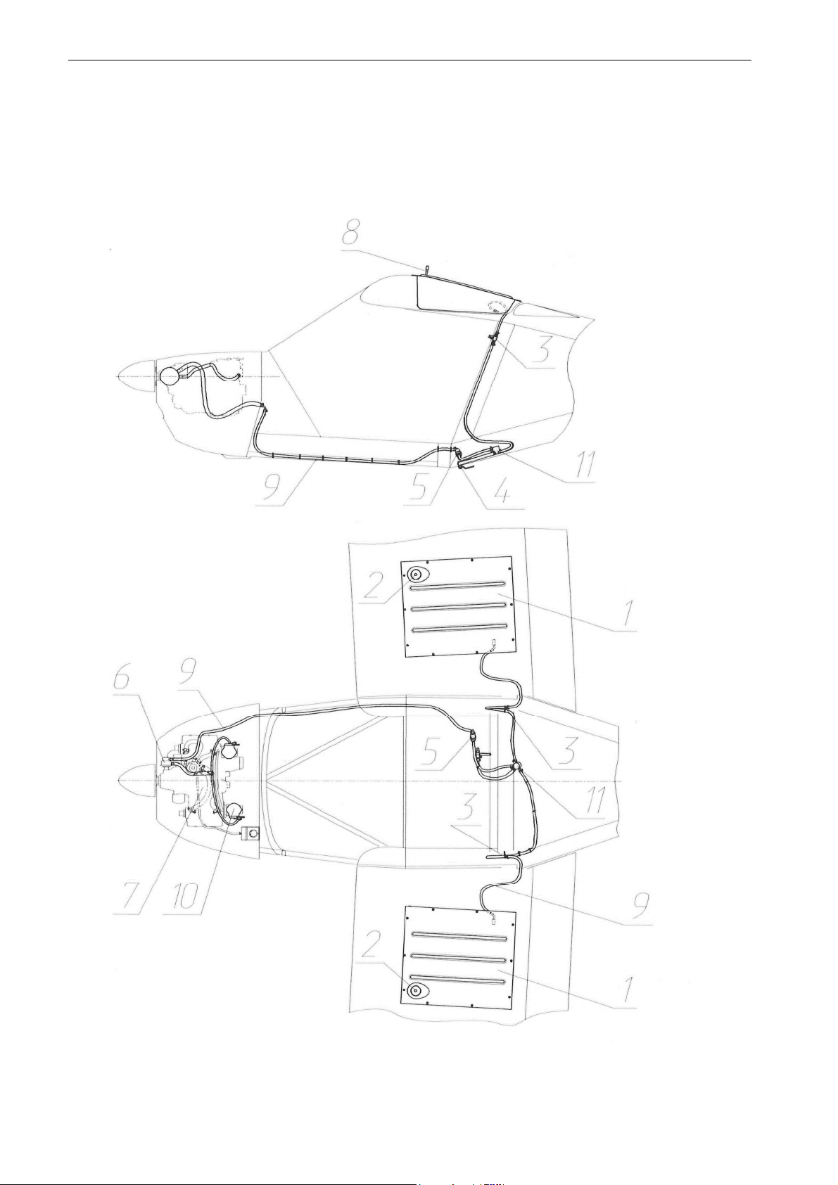
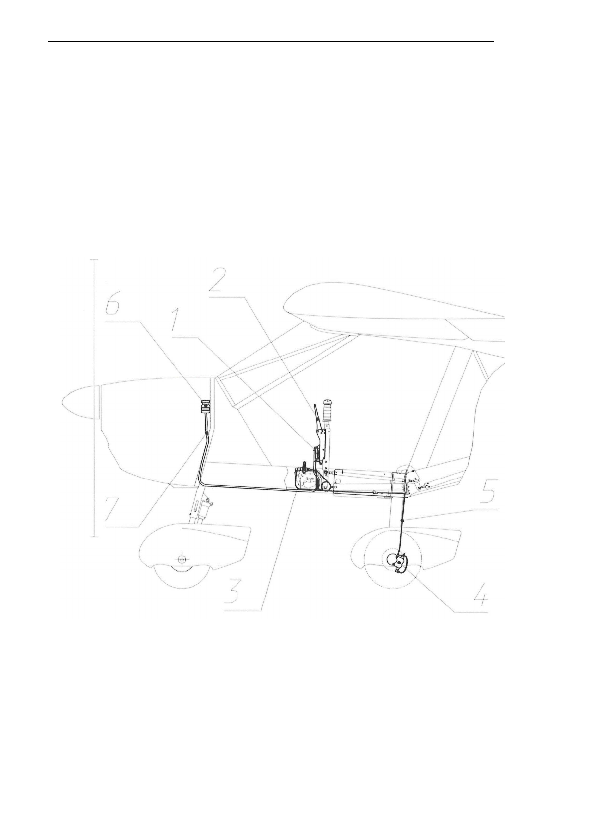
2.5 Fuel
system
The fuel system (Fig. 2) includes two wing fuel tanks 1 with filler inlets 2 and fuel lines 9
connecting the tanks to each other and to the engine fuel pump 6 (that is feeding fuel to
the engine carburetors 10) via two fuel valves 3, gascolator 11 and fuel filter 5. Fuel can
be
drained from the tanks using the drain valve 4. The fuel tanks are connected with the
atmosphere via the vent lines
8.
Capacity of each fuel tank is 45 I or 11,9 US
gal.
Fig. 2. Fuel system
schematic

A22L
2
-
POH
-
02
AEROPRAKT
-
22L2
Pilot
Operating
Handbook
10
NOTE: When both tanks are full, fuel may flow from one tank to the other
(e
.
g
.
due to
the
lateral forces during side slipping or when wings are not level on parking or during
taxiing
)
,
overfill it and spill out through the vent
line
.
To prevent fuel spilling out in this case it
is
recommended to close one of the fuel valves and avoid side-slipping in
flight.
CAUTION! At all times during the flight ensure fuel coming to the engine by
opening
the valve(s) of the tank(s) WITH fuel. If one of the tanks is empty,
close
its valve to prevent air getting into the fuel line and causing
engine
malfunction or even
failure.
Capacity of
tanks:
Total
capacity:
Usable
fuel:
Non-usable
fue
l
:
Fuel:
2x45 I (2x11,9 US
gal)
90 I (23,8 US
gal)
89 I (23,5 US gal)
1 I (0,3 US gal)
unleaded MOGAS
min
.
RON 95 or AVGAS
100LL
2.6 Airplane control
systems
Airplane control systems include control systems for drooping ailerons (flaperons),
elevator
with trim tab, rudder and nose wheel, engine and
brakes.
The control system is combined consisting of foot- and hand-actuated
subsystem
s
.
Ailerons and elevator are hand-actuated and are controlled using
yokes.
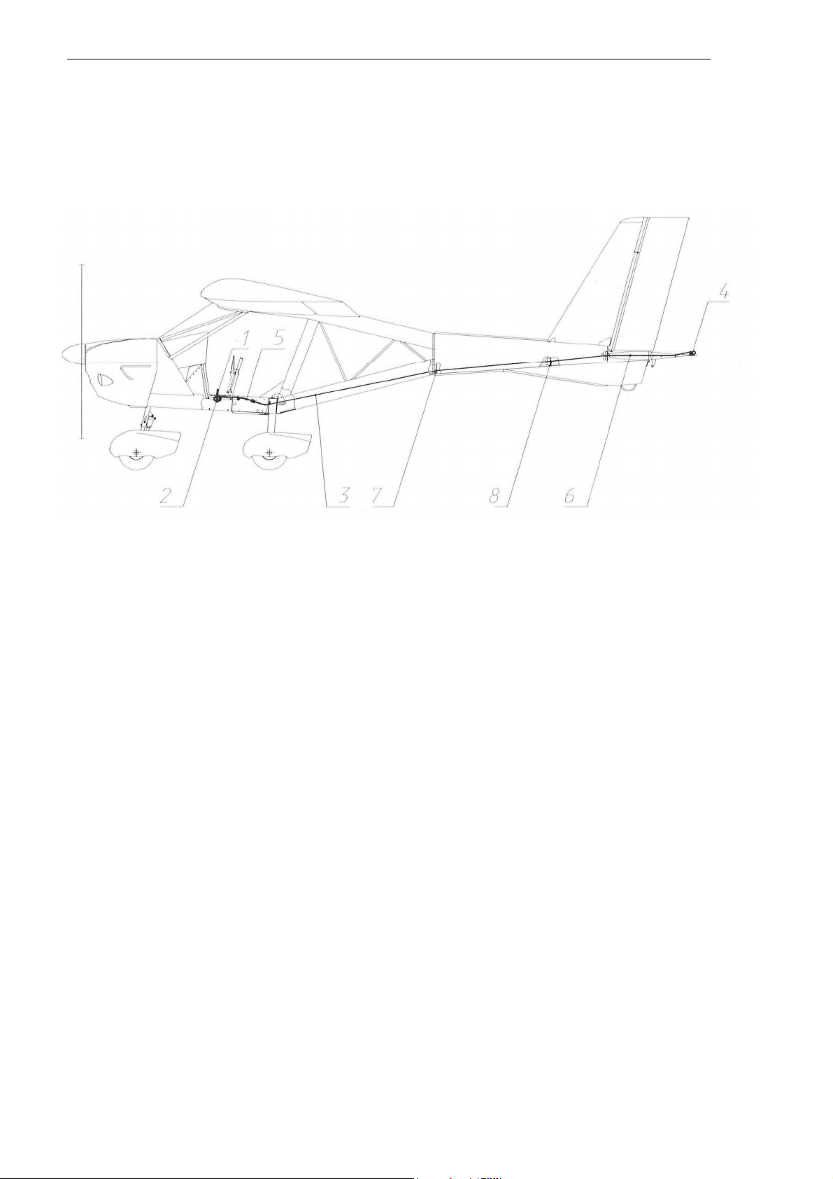
2.6.1 Elevator control
system
The elevator control system linkage (see Fig. 3) is rigid, compns1ng 3 pushrods and 2
bellcranks
.
"Push" and "pull" forces are applied by the pilot to the stick 1 is passed via
the
control column 2 to the pushrod 3, then via the bellcrank 4 to the pushrod
5.
The force
is
transferred to the elevator via the pushrod 7, attached to the bellcrank 6. And the
pushrod
7 is supported by the rollers 8 and connected to the elevator arm 9.
Fig.
3
A22L2
-
POH
-
02
AEROPRAKT
-
22L2
Pilot
Operating
Handbook
11
2.6.2 Elevator trim tab control
system
Elevator trim tab is used for controlling the force on control yokes in pitch. The trim
tab
control lever is
accessible
from both pilot
seat
s
.
Fig.
4
The trim tab control lever 1 (Fig. 4) is placed on the central console. It is retained in
place
by friction
adjusted
using the wheel 2.
The trim tab control lever is
connected
with a cable 3 to the trim tab control arm 4.
The
cable is running through the flexible
conduits5
(in the central console) and
6
(in
stabilizer
)
and cable
fairleads
7
and
8
inside the tail boom. The trim tab is hinged to the
elevator
trailing edge on a wire serving also as a torsion
spring.
The trim tab angles of
deflection
are: upward
21±1
°
,
downward 22±1°
.
A22L
2
-
POH
-
02
AEROPRAKT
-
22L2
Pilot
Operating
Handbook
12
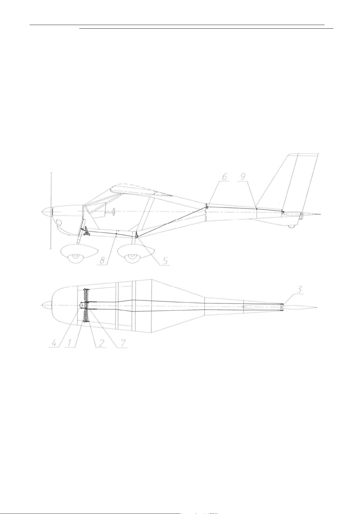
2.6.3 Rudder and nose wheel control
system
Rudder and nose landing gear are controlled using pedals. Rudder is connected to
the
pedals in the cockpit with two cables of 2.7 mm (0.11 in) diameter. The pedals
are
attached to two shafts (shaft for left pedals 1 and shaft for right pedals 2) hinged to
the
lower fuselage beams (Fig.
5).
Each shaft has two arms. One of the arms is
connected
with a cable to the rudder control arm 3, the other
-with
a rod - to the nose landing
gear
control arm
4.
Rudder control cables are running from the pedals to the rudder
control
arms via pulleys
5,
6 installed at frames No. 3 and 4 and fairleads 8, 9 on pilot seat
beam
and frame 5. Tension of the cables is adjusted using turnbuckles 7 attached to the
pedal
shaft arms.
In its neutral position the rudder is rotated to the right by the angle of +2°20'
for
compensation of the engine torque. The rudder deflection angle is 25±
1
°
.
Fig. 5. Rudder and nose landing gear control
system

A2
2
L
2
-
P
O
H
-
02
AEROPRAKT
-
22L2
Pilot
Operating
Handbook
13
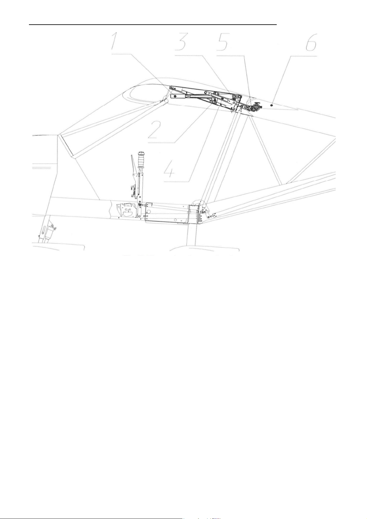
2.6.4 Control system of flaperons (drooping
ailerons
)
The airplane is equipped with flaperons (drooping ailerons), which serve as both
ailerons
and
flaps
.
The flaperon control system ensures independent function of flaperons as
ailerons and flaps using a differential
mechanism.
Fig. 6. Control system of flaperons (drooping
ailerons
)
The control force in roll (Fig. 6) applied by the pilot to the control stick 1 is passed to the
central control shaft 2. Then from the bellcrank 9 attached to the shaft it is passed via the
pushrods 7 to the flaperon control shafts 6. The shafts are attached via a Cardan joint 5 to
the bracket at the root end rib of the flaperon 4 at one end and to the trunnion on the
levers 3 of the flap control mechanism at the other. Stop 8 limits the rotation angle of
bellcrank 9 on the central control shaft and, therefore, angles of yoke rotation and
aileron
deflection
Deflection angles of the flaperons (as ailerons):
up-19±1°,
down
-13±
1
°
.
AEROPRAKT-22L2
Pilot Operating Handbook
A22L2
-
POH
-
02
14
Fig. 7. Flap extension
mechanism
As flaps (Fig. 7) the flaperons are extended by setting the flap extension lever 1 to
the
required positions and thus rotating the flap shafts 5 by the respective angles via link 3
and
levers 4. Locking of the flap setting is achieved by means of the stopper block 2 with
three
slots for the locking pin on the flap extension lever. Unlocking is achieved by bending
the
flexible flap extension lever to the side and thus taking the locking pin out of the fixing slot.
When the required flap setting is selected the locking pin is aligned with the fixing slot
and
the flap extension lever springs back inserting the locking pin into the fixing
slot.
Deflection angles of the flaperons (as flaps):
1
51
position
-10±1
°
,
2nd
position-
20±
1
°.
2.6.5 Engine
controls
The engine controls are accessible from both right and left side pilot seat. Engine RPM
is
controlled using a single throttle lever located on the central console. Two control
cables
connect the throttle lever to the left and right carburetors on the
engine
.
The fuel mixture control (for engine starting) is achieved using the choke lever also
located
on the central console near the throttle lever. The choke lever is connected to the
carburetors with cables as well.
Carburetor heating control knob is located on the instrument panel. It controls position of a
shutter in the air intake box. When the shutter is open, the colder outside air is
coming
through the air scoop into the air intake box and then to the carburetors. When the
shutter
is closed, the carburetors are supplied with the hotter air from the engine compartment and
thus the carburetor heating is ensured.
15
AEROPRAKT
-
22L2
Pilot
Operating
Handbook
A22L2
-
POH
-
02
2.6.6 Brake control
system
The main wheel brakes (Fig. 8) are actuated hydraulically using the brake lever 2
(
installed
next to the throttle lever 3) controlling the pressure supplied from the master cylinder 1
to
the slave cylinders 5 in the
wheels.
The main LG wheels have disk brakes. The cylinders are connected to each other with
copper tubing 6 with outside diameter of 3 mm. The master cylinder 1 is connected with a
hose 8 to the extension tank 7, installed on the firewall in the engine
compartment.
When the brake lever is pulled the brake pads squeeze the brake disc creating the
braking
moment proportional to the applied
force.
A-22L2 is equipped also with a parking brake, which is actuated with a lever 4 on the
central console. To use the parking brake, set the lever to 'Parking brake ON', then
pull
and release the brake lever. The brake pads will remain pressed to the brake disc. To
release the parking brake set its control lever to its initial position ('Parking brake OFF'
)
.
Fig. 8. Brake control
system

16
A22L2
-
POH
-
02
AEROPRAKT
-
22L2
Pilot
Operating
Handbook
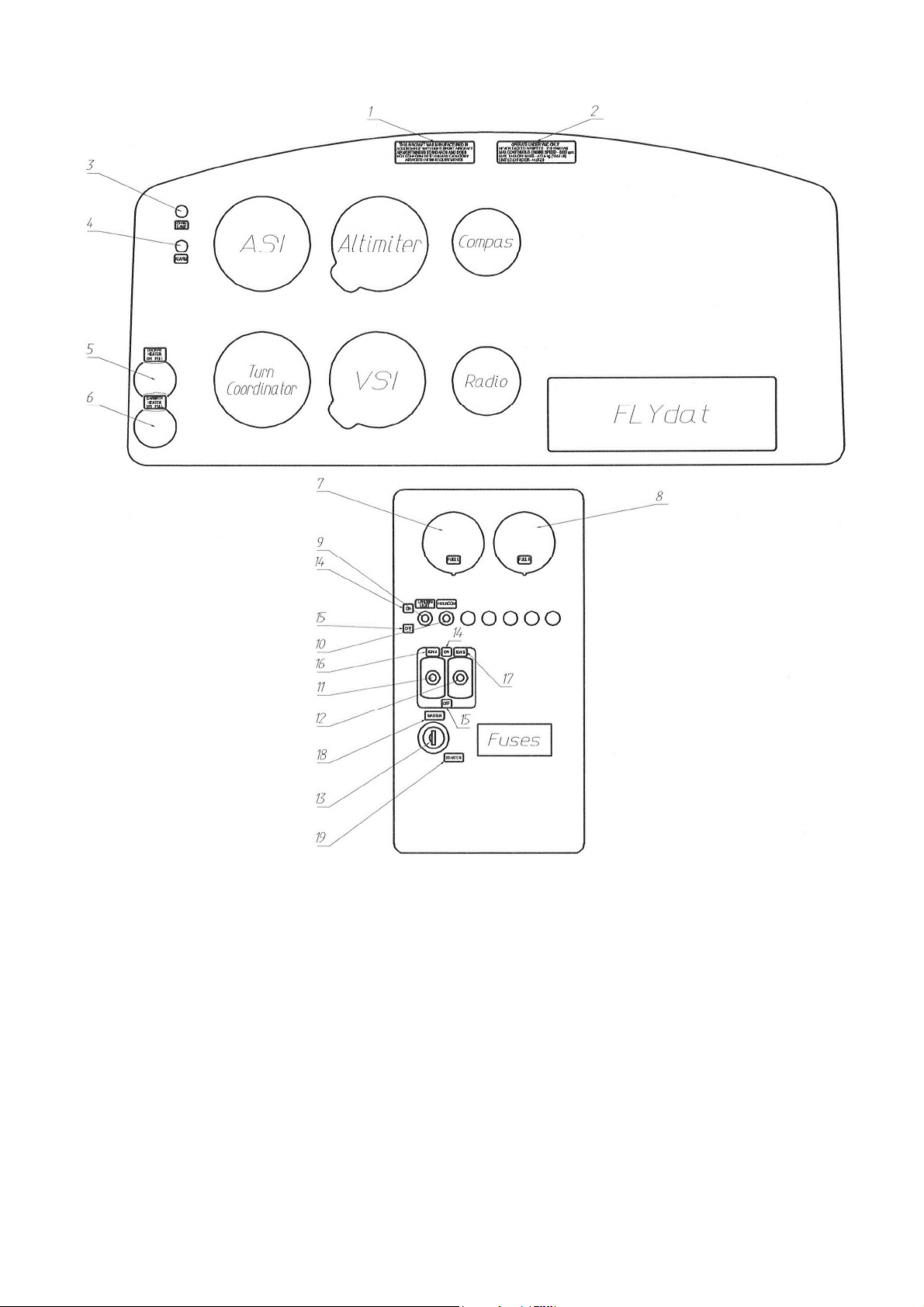
2.7 Instrument
panel
A-22L2 instruments set and instrument panel are represented on see fig.
Fig
.
9
Numbers in the pictures denote the followin
g:
1. Placard with passenger warning: "THIS AIRCRAFT WAS
MANUFACTURED IN
ACCORDANCE WITH LIGHT SPORT AIRCRAFT
AIRWORTHINESS STANDARDS
AND DOES NOT CONFORM TO STANDARD CATEGORY
AIRWORTHINESS
REQUIREMENTS"
2. Placard with operating limitations: OPERATE UNDER VFR ONLY
NEVER EXCEED
SPEED=
216 KM/H
lAS
MAX CONTINUOUS ENGINE SPEED = 5500
RPM
MAX TAKEOFF
MASS=
472.5 KG (1042 LB)
LIMIT LOAD
FACTOR=
+4.0
I
-2.0
3.
NO CHARGE indicator and
marking
4. ALARM indicator and
marking
5. Cockpit heating control knob and
marking
6. Carburetor heating control knob and
marking
7. Left tank fuel level indicator and marking "FUEL L"
8.
Right tank fuel level indicator and marking "FUEL R"
9.
Landing light switch and
marking
10. Intercom switch on/off switch and
marking
11.1GN
A switch
12. IGN B switch
13. Master and starter
key
14. ON marking for electric and ignition switches
15.
OF marking for electric and ignition switches
16. IGN A
marking
17. IGN B
marking
18. Master
marking
19. Starter
marking
17
AEROPRAKT
-
22L2
Pilot
Operating
Handbook
A22L2
-
POH
-
02
Fig.
9
18
A22L2
-
POH
-
02
AEROPRAKT
-
22L2
Pilot
Operating
Handbook
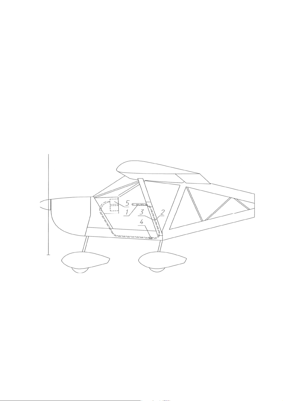
Full and static pressure
system
The full and static pressure probe (5) is located on the left wing strut. It supplies
the
pressure to the airspeed
indicato
r.
This system supplies the full (dynamic) and static pressure of the outside air to the
instruments measuring the flight parameters: airspeed, rate of climb and altitude.
The
system consists of the full and static pressure probe 1 and full 2 and static
3
pressure
lines
connecting the probe to the instruments (see Fig. 10). Full and static pressure lines
have
joints 4 used to disconnect the lines when the left wing is removed during
aircraft
disassembly.
The full and static pressure lines are connected to the airspeed
indicato
r
.
The
altimeter
and vertical speed indicator are connected to the static pressure
line
.
Good condition of the full and static pressure system is important for correct
measurement
of the flight parameters and therefore for flight safety. Pilots must take all
measures
necessary to keep the system in good condition. During the preflight check pilot
must
remove the cover from the full and static pressure probe and inspect the probe and lines
to
make sure that they are not damaged or blocked (by water, ice, dirt, etc.). After flight
pilot
must put the cover back on the probe.
Fig. 10. Full and static pressure
system
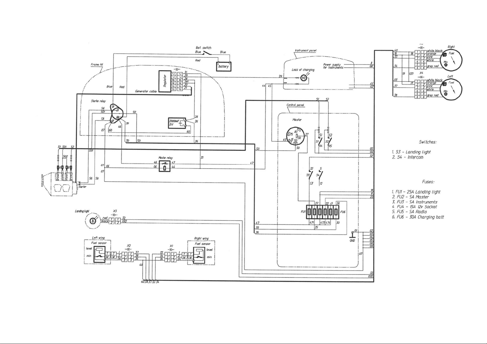
2.8 Electric
system
Electric system of A-22L2 serves for generation of electric power and supplying it to
the
onboard electric
consumers
.
When engine is running (its RPM is above 1400), electric power is generated by the
engine alternator, converted by a rectifier-regulator (located on the firewall) and is stored
in
a 12V DC 19Ah battery, located behind the left pilot seat. The battery is supplying
electric
power to the consumers (engine starter, instruments, lights, etc.) through the
electric
cables of appropriate section (depending on the consumed current), switches and
fuses
(located on the instrument panel)
.
The fuses are required to protect the electric
system
and consumers from excessively high current and must be of appropriate type and size.

19
AEROPRAKT
-
22L2
Pilot
Operating
Handbook
A22L2
-
POH
-
02
When battery is supplying power to the consumers while alternator is not generating
and
supplying power to the battery (e.g. engine is not running or due to some other
reason)
NO CHARGE light signals that the battery is discharging and its power may be lost
after
some time. When alternator starts recharging the battery NO CHARGE light goes out.
MASTER switch controls power supplies of all onboard consumers (except for the
engine
ignition system and consumers with their own built-in power source, e.g. GPS) together
with the electric switches for separate consumers. The engine ignition system may
be
switched ON/OFF only with the ignition
switches.
Electric system wiring depends on the electric equipment/instruments installed in the
aircraft and therefore have main and additional (optional) portions. The respective
wiring
diagrams are shown on
Fig
.
11
-Fig. 15.
A22L2
-
POH
-
02
AEROPRAKT
-
22L2
Pilot
Operating
Handbook
AEROPRAKT-22L2
Pilot Operating Handbook
Fig. 11. Wiring diagram of A-22L2 electric system
(
main
)
21
This manual suits for next models
2
Table of contents
Other AEROPRAKT Aircraft manuals

AEROPRAKT
AEROPRAKT N226AM Owner's manual

AEROPRAKT
AEROPRAKT A32-214-POH Owner's manual

AEROPRAKT
AEROPRAKT A32 User manual

AEROPRAKT
AEROPRAKT A32-103-POH Owner's manual

AEROPRAKT
AEROPRAKT A32-iS-129-POH Owner's manual

AEROPRAKT
AEROPRAKT A32 Owner's manual

AEROPRAKT
AEROPRAKT 22LS Owner's manual

AEROPRAKT
AEROPRAKT A32-029-POH Owner's manual

AEROPRAKT
AEROPRAKT A22LS Owner's manual

AEROPRAKT
AEROPRAKT AEROPRAKT-32L Owner's manual


