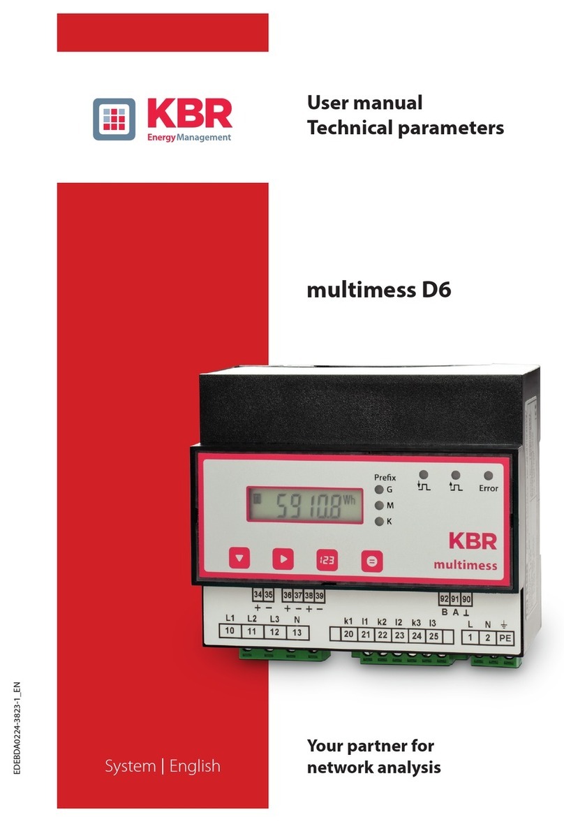
Citel LSCM-D User manual

User Manual
Smart SPD Monitoring Device
Surge Current Counter
LSCM-D
N210201 - This document could be modified without notice. Update available on website.

France
Head Office
Sales department
Sèvres, France
Tel: +33 1 42 23 50 23
e-mail: [email protected]
Web: www.citel.fr
Shanghai · China
Tel: +86 21 5812 2525
e-mail: [email protected]
Web:www.citel.cn
Address:No.88,Shangke Road,
Zhangjiang Hi-Tech Park, Pudong,
Shanghai, China

1-1 Overview: LSCM-D
1-2 Main functions
1-3 Technology and features
1-3-1 Technology
1-3-2 Main features
2-1 Mechanical scheme
2-2 Interface introduction
2-2-1 Power supply
2-2-2 RS485 ports
2-2-3 Sensor
2-2-4 Alarm input
2-2-5 Alarm output
2-2-6 PE shield connection
2-3 Typical wiring diagram for LSCM-D
P1/6
Introduction
P7/10
Installation
SAFETY INSTRUCTIONS
- Installation must be performed only by electrically skilled operator.
- National electrical installation rules must be followed.
- The unit must be used only as surge current counter & SPD monitoring, according the
conditions described in this document.

4-1 Introduction
4-2 Read device information
4-3 Write device information
3-1 Main operator panel
3-2 Main operator interfaces
3-2-1 First page-basic information
3-2-2 Second page-switch status
3-2-3 Third page-surge current information
3-2-4 Fourth page-status information of the content system
3-3 System setting3-3-1 Setting introduction
3-3-2 First page-system settings
3-3-3 Second page-system settings
P11/17
OLED Instructions
P18/29
Modbus Protocol

1 - Introduction
1-1 Overview: LSCM-D
As we know, surge voltages caused by lightning strikes can lead to severe damages and destructions to power and signaling
networks, such as common buildings, new energy plant structures like wind turbines. SPDs (Surge Protective Devices) are currently
used to tackle this important threat.
The monitoring of the SPDs is critical point for 2 reasons :
• Estimating the surge stress applied to the SPDs, for prostective
maintenance (SPD replacement before failure) and possible
upgrade the surge protection strategy (increase the discharge
current of the installed SPD because too heavy or too frequent
surges). For this, the timing, location and current amplitude of the
surge events must be known.
• Knowing the status (operating/disconnected) of
Surge Protection Branch (SPD + associated discon-
nectors e.g.MCB, fuse ) and transmission on this
information remotely.
01
LSCM-D User Manual

The Solution :
The smart monitoring and measuring device LSCM-D is designed for measuring the surge current which will flow in the Surge
protection branch and for indicating the the status of the SPD and and its associated disconnectors .
The product LSCM-D is composed of one sensor and one monitoring unit, detailed combinations are described as below table.
02
LSCM-D User Manual
1-Introduction
12-24 Vdc/ac Power Supply
120-230 Vac Power Supply
300 A minimum surge detection
1000 A minimum surge detection
12-24 Vdc/ac Power Supply + 300 A minimum detection
120-230 Vac Power Supply + 300 A minimum detection
12-24 Vdc/ac Power Supply + 1000 A minimum detection
120-230 Vac Power Supply + 1000 A minimum detection
Type
LSCM-D/24
LSCM-D/230AC
LSCM-P300
LSCM-P1000
LSCM-D/24/P300
LSCM-D/230AC/P300
LSCM-D/24/P1000
LSCM-D/230AC/P1000
Description Version
Monitoring unit
Monitoring unit
Surge sensor
Surge sensor
Complete set: 1 monitoring unit+1 sensor
Complete set: 1 monitoring unit+1 sensor
Complete set: 1 monitoring unit+1 sensor
Complete set: 1 monitoring unit+1 sensor

1-2 Main functions
The main funcitons for LSCM-D described as below :
Lightning and surge current detection for wide detection
range :
- 0.3/25kA@10/350s or 0.3/50kA @ 8/20s(LSCM-P300)
- 1.0/50kA@10/350s or 1.0/100kA @ 8/20s(LSCM-P1000)
Front OLED display can read recorded events and device
parameters
Peak current and time stamping recording of the surge
events
RS485 communication interface/MODBUS protocol
Monitor connected devices: with two inputs and one
output switch signal, the status of SPD and/or backup
protection can be monitored.
Equipped with rechargeable 3 V battery, which can
keep the clock running in case of power loss, to ensure
the accuracy of recording time;
Equipped with an LED indicator light can indicate the
working status of the equipment.
03
LSCM-D User Manual
1-Introduction

This measuring system utilizes Faraday effects to analyze the surge
currents which pass through conductors when discharge happens.
The measured electric signals caused by electromagnetic effects is
generated in the coil sensor, and will be transfered into differential
voltage signal to monitoring unit through sensor’s connection wire,
then the controlling unit proceed further back
calculation by microprocessor.
The data acquisition system for incoming surges
consists of signal conditioning circuit, DSK interfacing
circuit, RS-485 communication interfacing circuit,
system clock circuit, power supply circuit and so on.
System schematic diagram Fig 1.
1-3 Technology and features
1-3-1 Technology
Serial port convert
to RS485
Signal amplifier
RS485 COM Ports
Internal Flash
Memory:128KB
USART2
Differential ADC
signal acquisition SPI
DC-DC module
24Vdc/230Vac
power input
Program burn port
SWD
USART1
Internal SRAM:
packaging
Voltage signal
measured by sensor OLED display module
I2C
WIFI module
USART1
GPIO
Alarm input/output
GPIO
Key control
GPIO
LED status
REF signal
Sensor
Monitoring Unit
GPIO
Fig1. LSCM-D system schematic diagram
04
LSCM-D User Manual
1-Introduction

1-3-2 Main features
Surge current detection
The peak value and polarity of surge currents flowing
conductors, including PE wires or down conductor, as well
as the time stamping for the event are recorded. Long
(10/350µs) and shorter (8/20µs) duration impulse currents
can be monitored with wide range (range described as 1 -2).
Monitor the state of the SPD and its associated discon-
nectors (operating/disconnected)
This information will send through the communication line
or will operate a contact (output port) to activate a LED
indicator, or a buzzer, or a contactor to cut down the main
circuit (Fig4).
With high precision
The accuracy rate for LSCM-D can declare within +/-5%. The
precision could reach better performance in low electromag-
netic interference conditions.
Wide operating voltage range
The power supply is equipped with rectifying bridge, which can
support DC and AC wide voltage range input, and applicable for
reverse wiring, two versions optional:
•DC power supply: 12-24Vdc/ac (DC:9Vdc min/36Vdc max;
AC:6Vac min/30Vac max)
• AC power supply: 120-230Vac (90Vac min/264Vac max)
05
LSCM-D User Manual
1-Introduction

Information display and communication
•Local information: the front OLED display gives access
the recorded information (surge parameters, devices status)
•Remote signal communication: a remote computer,
through RS485 communication/Modbuis protocol to the
LSCM-D, can access to the full recorded data.
Higher immunity to interference
LSCM-D have passed strict tests on EMC and EMI, comply
with the standard requirements on IEC 61000 and CISPR.
Built-in battery for timer
To ensure the accuracy of recording timethe monitoring
device equipped with rechargeable 3V battery which can
keep the timer running in case of power loss the battery life
could reach 3-6 months.
Wide applicability
Based on the compact design and wide surge detection
range for 10/350s and 8/20s, LSCM-D typically can be
used for:
•Detect the surge current via SPD PE wire inside an
electrical cabinet
•Monitor the state of SPD and/or of its associated
disconnector (fuse/MCB)
•Detect the lightning current flowing PE wire from blade
to the hub in windturbine.
•Detect the direct lightning strike from LPS through down
conductor or grounding wire.
06
LSCM-D User Manual
1-Introduction

2- Installation
Monitoring unit LSCM-D
90
53.8
73.5
Sensor LSCM-P1000
12
40
50
Fig2. Mechanical scheme for LSCM-D
2-1 Mechanical scheme
07
LSCM-D User Manual

2-2 Interface introduction
2-2-1
Power supply
The applicable voltage for power supply is 12-24
Vdc/ac or 120-230Vac (two different versions)
(please refer to 1-3-2).
2-2-2 RS485
ports
RS485 ports is designed for communicating with
remote computer to transmit the detecting data
and monitoring instructions : this system uses
half-duplex communication by the way of Modbus
transmission protocol. RS485 communication
cable in general is using twisted pair, but under the
high requirement of environment suggest to use
shielded twisted pair cables, to achieve perfect
performance of anti-interference.
2-2-3 Sensor
LSCM-D equipped with dedicated coil sensor for surge measuring : two
versions ar available for different detection range. The sensor should be
mounted around the discharge conductors as fig4 shows. The connection
wire (default configuration) should connect to monitoring unit.
2-2-4 Switching signal-Alarm inputs
The device is equipped with two alarm input ports for monitoring the
switching state from SPD and/or disconnectors. The received switching
state information will transfer to the alarm output port and remote
computer through RS485 in real time. Tthe “alarm” process can be
triggered by setting the fault state for each input ports.
2-2-5 Alarm output
Output port is designed for trigger the "alarm" process like LED/buzzer/-
contactor. The output signal status totally depends on the input signal
status. The maximum operating voltage and current for output ports is
350Vdc & 120mA.
08
LSCM-D User Manual
2-Installation

Fig3. LSCM-D connection
WW/YY
L
S
C
M
-
P
1
0
0
0
INPUT1 INPUT2 NC OUTPUT
24V SH. RS485 SENSORSH.
DC/AC
Connect to SPD remote signal
Connect to external disconnectors
Connect to DC/AC power Connect to sensor
Connect to PE conductor Connect to upper computer
Standby port
Connect to external alarm equipment
2-2-6
PE shield connection
The monitoring device should connect to the
earthing system with each one of the two SH
ports (Shield) . By this way, the system immu-
nity for LSCM-D can be increased and the
common interference through RS485 can be
reduced, so an higher measurement accuracy
can be ensured.
2-Installation
09
LSCM-D User Manual

2-3 Typical wiring diagram for LSCM-D
• Symmetrical DIN rail mounting
• Connection terminal : spring contact -1.5 mm² wire max
• Operating/storage temperature : -25/+70 °C
• Protection rating : IP20
• Weight:170g
• Maximum acceptable conductor diameter for sensor: 19mm
AC Power
24V/230V (depending of version)
Power Supply
Sensor connection cable
Connect to PE conductor (Shield)
MCB/Fuse
SPD
INPUT1 INPUT2 NC OUTPUT
24V SH. RS485 SENSORSH.
DC/AC
L N
or
Disconnection Contactor monitoring
Remote contact of external disconnector for SPD
SPD remote signal
Sensor
RS485 communication
MODBus protocol
Fig4. Typical wiring diagram for LSCM-D
*Note: 1) two input ports are totally identical, so the wiring can be reversed.
2) the monitoring unit should keep power off when wiring : using this
way can avoid triggering by accident due to signal interference and
other factors.
10
LSCM-D User Manual
2-Installation
Remote Computer

3-1 Main operator panel
Monitoring unit equipped with one 128×64 OLED display screen and
three operating buttons like below, buttons from left to right are
defined as”▲▼■"respectively.
The main interface for OLED can be divided into four main operator
interfaces (3-2) and two system setting interface (3-3).
Buttons ▲▼ are used for pages switching between the main
interface. Button ■ is used for selection or confirmation .
After pressing Button ■for 5 seconds, the screem can access the
system setting interface and proceed to set system parameters.
11
3-OLED Instructions
LSCM-D User Manual

3-2 Main operator interfaces
3-2-1 First page : basic information
The first interface displays basic information for LSCM-D, including
manufacturer name, device designation, real-time clock time and date.
3-2-2 Second page : switch status
The second page displays disconnectors’ state, two input ports can display the
real time state for the connecting disconnectors like fuses or MCBs, and the
output port state can be set by modbus communication(4-3-1) according to differ-
ent state of input ports.
CITEL
SPD Monitoring
16:21:40
2020-08-10
SPD Monitoring
16:21:40
2020-08-10
CITEL
Switch Status
Input 1: Open
Input 2: Open
Output: Open
Switch Status
Input 1: Open
Input 2: Open
Output: Open
12
LSCM-D User Manual
3-OLED Instructions

3-2-3 Third page : Surge current information
The third page is the interface about surge current information. Press button ■
can access this page and detailled the recorded detected data (the latest 1200
surge events). It contains the polarity and peak value of lightning current, the time
and the sequence number. Button ▲▼ can switchover each surge events, press
button ■ can exit the query page.
001 Times
Peak: + 6.5 kA
Time: 16:23:01
2020-08-10
001 Times
Peak: + 6.5 kA
Time: 16:23:01
2020-08-10
3-2-4 Fourth page : Status information of the system
The fourth page displays the equipment information. Press button■
will display the current user device address(user-defined) and RS485
communication baud rate.
Press ■again will access next page, the device serial number and
software version can be queried in this page.
1. UserAddr:001
2.RS485:
9600,8,N,1
3.LSCM-P1000
1. UserAddr:001
2.RS485:
9600,8,N,1
3.LSCM-P1000
4. UserID
20200506000000000
5.Software Versi
on: 20200731
4. UserID
20200506000000000
5.Software Versi
on: 20200731
13
LSCM-D User Manual
3-OLED Instructions

3-3 System settings
3-3-1 Settings introduction
System setup is mainly used to set up system information, such as RS485 communication baud rate, user device address, languages
settings. Press the function button ■ more than 5 seconds can access the first system settings page, press button ▲▼ can move
the cursor in this page.
There are two pages for system setting.
• The first page as 3-3-2 described, RS485 baud
rate (default 9600 baud), user-defined device address
and language can be set at this page.
• The second page as 3-3-3 described, the type of sensor
can be selected between LSCM-P300 or LSCM-P1000, the
real time and clear record can be set too.
14
LSCM-D User Manual
3-OLED Instructions

3-3-2 First page : System settings
RS485 baud rate
After access the interface of RS485 baud rate selection, then move
the cursor by button ▲ and ▼ to choose the appropriate baud rate,
then press button ■ to confirm the selection.
User address
By using buttons ▲▼can modify LSCM-D communication address
with upper computer, and use button ■ to confirm code setting.
Language setup
Setting language, use buttons ▲ and ▼ can modify the
optional language for English and simplified Chinese,
and use button ■ to confirm the change.
If continue to press ▼, the second page for system
settings as 3-2-3 will display.
Set Up
RS485Baudrate
UserAddress
LanguageSetuo
Set Up
RS485Baudrate
UserAddress
LanguageSetuo
15
LSCM-D User Manual
3-OLED Instructions

3-3-3 Second page : System settings
Time setup
After access the second system setting page,
press button ■to enter the year setting, and use
buttons▲and▼to switch the year value. Month,
date and time setup take similar way.The time
can be set by the means of time synchronization
with upper computer, more simpleand fast than
the button way.
Sensor setup
After access the sensor setting interface, press button ■ to enter
the selection bar, the sensor type LSCM-P300 and LSCM-P1000 can
be selected by button ▲ and ▼.
After select the sensor, the lightning detection range also can been
set too, take LSCM-D/24/P1000 for example, three option "1kA-100-
kA", "2kA-100kA" and "4kA-100kA" optional, the range option
depend on the application requirements.
Be careful, if choose wrong sensor type, the measured value is
unreliable.
SENSOR SET
LSCM-P1000
LSCM-P300
SENSOR SET
LSCM-P1000
LSCM-P300
Time Setup
SENSOR Setup
Clear Record
Exit Setup
Time Setup
SENSOR Setup
Clear Record
Exit Setup
16
LSCM-D User Manual
3-OLED Instructions
This manual suits for next models
8
Table of contents
