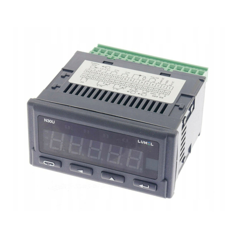
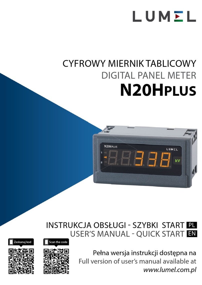
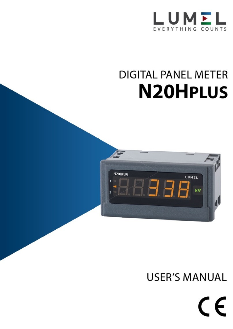
Lumel N30P User manual

1
DIGITAL
PANEL METER
N30P TYPE
USER’S MANUAL

2

3
Contents
1. APPLICATION and METER DESIGN..........................................5
2. METER SET..................................................................................6
3. BASIC REQUIREMENTS, OPERATIONAL SAFETY ................7
4. INSTALLATION............................................................................8
5. SERVICE ....................................................................................11
6. RS-485 INTERFACE .................................................................26
7. ERROR CODES .........................................................................44
8. TECHNICAL DATA ....................................................................46
9. ORDER CODES .........................................................................49
10. MAINTENANCE AND GUARANTEE.........................................51

4

5
1. APPLICATION AND METER DESIGN
The N30P meter is a programmable digital panel meter destined for the
measurement of a.c. voltage, a.c. current, active, reactive and apparent
power, cos ϕ, tg ϕ, ϕ, frequency, active, reactive and apparent energy,
15 minutes’ active power, 10 minutes’ voltage, 10 seconds’ frequency.
Additionally, the meter enables the indication of the current time. The
readout field is composed of a display which allows to expose results in
red, green and orange colours.
Features of the N30P meter:
zdisplay colour individually in three ranges,
zthresholds of displayed overflows,
z2 NOC relay alarms operating in 6 modes,
z2 switched relay alarms operating in 6 modes (option),
zsignaling of measuring range overflow,
zautomatic setting of the decimal point,
zprogramming of voltage and current ratios,
zprogramming of alarm and analog outputs with the reaction on any
measured value, independently of the currently displayed value,
zstorage of maximal and minimal values of all input quantities,
zreset of all watt-hour meters: active and reactive energy,
zprogrammed kind of 15 minutes’ active power measurement: mean
walking or synchronization with the RTC clock,
zmanual synchronization of 15 minutes” power, 10 minutes’ voltage,
zmonitoring of set parameter values,
zinterlocking of parameter introduction by means of a password,
zservice of the interface with MODBUS protocol in the
RTU mode (option),
zconversion of the measured value into a standard – programmable
current or voltage signal (option),

6
2. METER SET
The set is composed of:
- N30P meter ......................................... 1 pc
- User’s manual ..................................... 1 pc
- Guarantee card................................... 1 pc
- Clamps to fix in the panel ................... 4 pcs
- Seal ..................................................... 1 pc
When unpacking the meter, please check whether the type and execu-
tion code on the data plate correspond to the order.
zhighlighting of any measuring unit acc. to the order,
zgalvanic separation between terminals: alarm, supply, input,
analog, pulse output, RS-485 interface.
The switching of the alarm output on, is signaled by the highlighting of
the output number.
The casing protection grade from the frontal side is IP 65.
Meter overall dimensions: 96 48 93 mm (with terminals).
The meter casing is made of plastics.
Fig. 1 View of the N30P digital meter

7
3. BASIC REQUIREMENTS, OPERATIONAL
SAFETY
In the safety service scope, the meter meets the requirements of the EN
61010-1 standard.
Observations concerning the operational safety
· All operations concerning transport, installation, and commissioning
as well as maintenance, must be carried out by qualified, skilled
personnel, and national regulations for the prevention of accidents
must be observed.
· The programming of N30P meter parameters must be carried out
after disconnecting measuring circuits
· Before switching the meter on, one must check the correctness of
connections to the network.
· Do not connect the meter to the network through
an autotransformer.
· Before removing the meter housing, one must switch the supply
off and disconnect measuring circuits.
· The removal of the meter housing during the guarantee contract
period may cause its cancellation.
· The meter fulfills requirements related to electromagnetic
compatibility in the industrial environment
· When connecting the supply, one must remember that a switch or
a circuit-breaker should be installed in the building. This switch
should be located near the device, easy accessible by the
operator, and suitably marked as an element switching
the meter off.
· Non-authorized removal of the housing, inappropriate use, incorrect
installation or operation, creates the risk of injury to personnel or
meter damage. For more detailed information, please study the
User’s Manual.

8
Fig. 2. Meter fixing
4. INSTALLATION
The meter has separable strips with screw terminals which enable the
connection of external wires of 2.5 mm2cross-section. In execution for
current measurement, the plug enables a permanent fixing to the so-
cket by means of screws.
The meter is adapted to be mounted in a panel by means of clamps,
acc. to the fig. 2. One must prepare a hole of 92+0.6 45+0.6 mm in the
panel which the thickness should not exceed 6 mm.
The meter must be introduced from the panel front with disconnected
supply voltage. Before the insertion into the panel, one must check the
correct placement of the seal. After the insertion into the hole, fix the
meter by means of clamps (fig.2).

9
4.1. Connection Diagrams
Fig. 3. Overall dimensions
Fig. 4. Electrical connections of the N30P meter
for direct measurements

10
Fig. 5. Electrical connections of the N30P meter
for indirect measurements

11
5. SERVICE
5.1. Display Description
Fig. 6. Description of the meter frontal plate
5.2. Messages after switching the supply on
After switching the switching supply on, the meter displays the meter
name N30P and next the program version in the shape „r x.xx” – where
x.xx is the number of the current program version or the number of
a custom-made execution. Next the meter carries out measurements
and displays the value of the input signal. The meter sets automatically
the decimal point position when displaying the value, using prefixes
k – kilo, M – mega. The overflow of alarm thresholds is signaled by
highlighting alarm indexes 1, 2, 3, 4 and switching relays (for alarm 3
and 4 –relays are as option). The meter highlights automatically the unit
of the measured value. In case of an error occurrence or any exceeding
of the range value, a message described in the chapter 7 will be dis-
played on the display.

12
5.3. Functions of buttons
- Acceptation button:
⇒ entry in programming mode (hold down ca 3 secondes)
(przytrzymanie przez oko³o 3 sekund),
⇒ moving through the menu – choice of level,
⇒ moving through the menu monitoring the measured values,
⇒ entry in the mode changing the parameter value,
⇒ acceptation of the changed parameter value.
- Button increasing the value:
⇒ display of maximal value,
⇒ display of maximal value – menu monitoring the measured
parameters,
⇒ entry in the level of the parameter group,
⇒ moving through the chosen level,
⇒ change of the chosen parameter value – increasing the value.
- Button to change the digit:
⇒ display of minimal value,
⇒ display of minimal value – menu monitoring the measured
parameters,
⇒ entry in the level of parameter group,
⇒ moving through the chosen level,
⇒ change of chosen parameter value – shift on the next digit,
⇒ next parameter in the monitoring mode of meter parameters.
- resignation button:
⇒ entry in the menu monitoring the meter parameters (holding down
ca 3 seconds),

13
⇒ exit from the menu monitoring meter parameters and measured
values,
⇒ resignation of the parameter change,
⇒ absolute exit from the programming mode.
The pressure of the button combination and holding
down them ca 3 seconds causes the reset of alarm signaling. This ope-
ration acts only when the support function is switched on.
The pressure of the button combination causes the
erasing of all minimal values.
The pressure of the button combination causes the
erasing of all maximal values.
The pressure and holding down the button ca 3 seconds
causes the entry to the programming matrix. The programming matrix
is protected by the safety code.
The pressure and holding down the button 3 seconds causes
the entry to the menu monitoring meter parameters. One must move
through the monitoring menu by means of and buttons.
In this menu all programmable meter parameters are only accessible
for readout, excepting service parameters. The exit for the monitoring
menu is carried out by means of the button. In the monitoring
menu, parameter symbols are displayed alternately with their values.
The service algorithm of the meter is presented on the fig. 7.
The pressure and holding down and buttons, ca 3 se-
conds, causes the entry to the menu monitoring measured values. One
must move through the monitoring menu by means of ,
and buttons.
The pressure of the button causes the display of successive
symbol of measured value alternately with the value. The pressure of
the button causes the display of minimal value of the currently

14
Fig. 7. Algorythm of the N30P meter service

15
displayed value, however the pressure of the button causes the
display of the maximal value of the currently displayed value.
The exit from the monitoring menu is carried out by means of the
button.
5.4. Programming
The pressure of the button and holding it down through ca 3
seconds causes the entry to the programming matrix. If the entry is pro-
tected by a password, then the safety code symbol SEC is displayed
alternately with the set value 0. The write of the correct code causes
the display of the ErCod inscription. The matrix of transitions to the
programming mode is presented on the fig. 8. The choice of the level is
made by means of the button , however the entry and moving
through the parameters of the chosen level is carried out by means of
the and buttons,
Parameter symbols are displayed alternately with their current values.
In order to change values, one must use the button. To resign
fo the parameter change, one must press the button. In order
to exit from the chosen level, one must chose the ----- symbol and press
the buton or press the button . To exit from the program-
ming matrix, one must press several times the button till the
appearance of the inscription End and after ca 3 seconds, the meter
enters automatically in the measurement of the input quantity.
Value Change Way of the Chosen Parameter
Change of Integral Values
In order to increase the value of the chosen parameter, one must
press the buton. The single pressure of the button, causes
the increase of the value of 1. The holding down of the button

16
Fig. 8. Transition matrix in the programming mode
* Do not occur in the
execution without
additional output
plate.

17
causes a continuous increase of the value on the given digit. The increase
of value when displaying the digit 9 causes the setting of 0 on this digit.
The change of the digit follows after pressing the button.
In order to accept the set parameter, one must hold down the
button. Then, the saving of the parameter follows and the display of its
symbol alternately with the new value. The pressure of the but-
ton during the change of the parameter value will cause the resignation
of the write.
Changing of Values
The change is carried out in three stages (the transition to the next
stage follows after pressing the button:
1) setting the value from the range -19999M...99999M, similarly as for
integral values;
2) setting of the decimal point position (00000., 0000.0, 000.00,
00.000, 0.0000); the button shifts the decimal point to the
left, however the button shifts the decimal point to the right;
3) choice of the prefix: lack, k, M; the button switches the next
prefix; the chosen prefix is displayed in orange.
The pressure of the button during the change of the parameter
value will cause the resignation of the saving.

18
Table 1
Para-
meter
symbol
Description Range of changes
tYP Choice of the displayed quantity
U– RMS voltage
I – RMS current
P – active power
q– reactive power
S– apparent power
PF – factor of active power
tG – ratio of reactive power to the
active power
FI – phase shift
FrEq - frequency
EPPoS – active energy input
EPneg – active energy output
EqPoS – reactive energy input
Eqneg – reactive energy output
PAv – 15 minutes’ mean active power
UAv – 10 minutes’ mean voltage
FAv – 10 seconds’ mean frequency
HoUr – current time
SYn Type of input synchronization
U – synchronization with voltage
(measurement of all values)
I– synchronization with current
(only measurement of current and
frequency)
rAnU Choice of voltage range 100U – range 100 V
400U – range 400 V
rAnI Choice of current range 1A – range 1 A
5A – range 5 A
trU Choice of voltage ratio 1...4000.0
trI Choice of current ratio 1...10000
PAv S Synchronization of 15 minutes’ power
CntS – walking window
qUArt – measurement every quarter
of an hour synchronized with
the clock

19
dp Minimal position of the decimal point
when displaying the measured value.
0.0000 – 0
00.000 – 1
000.00 – 2
0000.0 – 3
00000 – 4
k 000.00 – 5
k 0000.0 – 6
k 00000 – 7
M 000.00 – 8
M 0000.0 – 9
M 00000 – 10
CoLdo Display colour when the displayed
value is less than CoLLo
rEd – red
GrEEn – green
orAnG – yellow
CoLbE
Display colour when the displayed
value is higher than CoLLo and less
than CoLHI
CoLUP Display colour when the displayed
value is higher than CoLHI
CoLLo Lower threshold of display colour
change -19999M ... 99999M
CoLHI Upper threshold of display colour
change -19999M ... 99999M
ovrLo Lower threshold of the display con-
straint
-----
”-19999M ... 99999M
ovrHI Upper threshold of the display
constraint
-----
”-19999M ... 99999M

20
P_A1
P_A2
P_A3
P_A4
Kind of input value type, which the
alarm has to react on.
U – RMS voltage
I – RMS current
P – active power
q– reactive power
S– apparent power
PF – active power factor
tG – ratio of reactive power to active
power
FI – phase shift
FrEq - frequency
EPPoS – active energy input
EPnEG – active energy output
EqPoS – reactive energy input
EqnEG – reactive energy output
PAv – 15 minutes’ mean active power
UAv – 10 minutes’ mean voltage
FAv – 10 seconds’ mean frequency.
PrL 1
PrL 2
PrL 3
PrL 4
Lower alarm threshold. -19999M ... 99999M
PrH 1
PrH 2
PrH 3
PrH 4
Upper alarm threshold. -19999M ... 99999M
tYP 1
tYP 2
tYP 3
tYP 4
Alarm type. The fig. 9. presents a
graphic display of alarm types.
n-on – normal (transition from 0 to 1),
n-oFF – normal (transition from 1 to 0),
on - switched on,
oFF – switched off,
H-on – manually switched on; till the
time of alarm type change, the alarm
output remains switched on for good.
H-oFF – Manually switched off; till the
time of alarm type change, the alarm
output remains switched off for good.
dLY_1
dLY_2
dLY_3
dLY_4
Delay of alarm switching. 0...120 seconds
Other manuals for N30P
1
Table of contents
Other Lumel Measuring Instrument manuals
Popular Measuring Instrument manuals by other brands

P3 International
P3 International P4460 Operation manual

SATA
SATA AE5809 user manual

ASCO POWER TECHNOLOGIES
ASCO POWER TECHNOLOGIES SIGMA Hand-held quick start guide

VOLTCRAFT
VOLTCRAFT VC-330 operating instructions

Rhopoint
Rhopoint NOVO-GLOSS operating instructions

LumaSense technologies
LumaSense technologies IMPAC IN 9 plus manual