CityEV Safevolt 50 Operating manual
Documentation
Revision 1.31, September 2020
Copyright © 2020 CityEV Limited
All Rights Reserved. All trademarks are
owned by CityEV Limited
CityEV Safevolt® 50
User and Installation
Manual
®
®

Page 2
Warranty 3
About Your System 3
Important Safety Information 3
The CityEV Safevolt® 50 5
Safevolt® 50 Operation 5
Positioning 7
Removing the cover 7
Connections 8
Electrical Testing 9
Precautions 9
General 9
10
Using SWA cables with Safevolt® 50 10
Safevolt® 50 Specifications 11
Contents
Contents

Page 3
Warranty
UNLESS SPECIFICALLY AGREED TO IN WRITING, SELLER
(A) MAKES NO WARRANTY AS TO THE ACCURACY, SUFFICIENCY OR SUITABILITY OF ANY TECHNICAL OR
OTHER INFORMATION PROVIDED IN ITS MANUALS OR OTHER DOCUMENTATION;
(B) ASSUMES NO RESPONSIBILITY OR LIABILITY FOR LOSSES, DAMAGES, COSTS OR EXPENSES, WHETHER
SPECIAL, DIRECT, INDIRECT, CONSEQUENTIAL OR INCIDENTAL, WHICH MIGHT ARISE OUT OF THE USE OF
SUCH INFORMATION. THE USE OF ANY SUCH INFORMATION WILL BE ENTIRELY AT THE USER’S RISK; AND
(C) REMINDS YOU THAT IF THIS MANUAL IS IN ANY LANGUAGE OTHER THAN ENGLISH, ALTHOUGH STEPS
HAVE BEEN TAKEN TO MAINTAIN THE ACCURACY OF THE TRANSLATION, THE ACCURACY CANNOT BE
GUARANTEED. APPROVED CONTENT IS CONTAINED WITH THE ENGLISH LANGUAGE VERSION WHICH IS
POSTED AT WWW.CITYEV.NET
Revision: 1.31 Date: September 2020
Product Part Number: Safevolt 50
About Your System
As soon as you open your product, record the following information and be sure to keep your proof of
purchase.
Serial Number
Product Number
Purchased From
Purchase Date
Important Safety Information
Warning conventions used in this manual
⚠DANGER indicates an imminently hazardous situation which if not avoided will result in death or
serious injury.
⚠WARNING indicates a potentially hazardous situation which, if not avoided, can result in
death or serious injury.
⚠CAUTION indicates a potentially hazardous condition.
All safety warnings give specific details of the potential danger/warning present and indicate how to
reduce risk of injury, damage and electric shock resulting from improper use of the device.
Important Safety Information

Page 4
Carefully observe the following instructions:
•Installation and maintenance must be carried out by a competent person, in compliance with the
manufacturer's instructions, the relevant wiring regulations and local safety regulations.
If in any doubt, consult a qualified electrician.
•The device must be disconnected from the power supply before carrying out any installation or
service work.
•Do not remove the device cover while the power supply is connected.
•Do not operate the device with the cover removed.
•Do not attempt to repair or replace any part of the device. In case of malfunction contact your
installer or CityEV Ltd.
•All maintenance operations must be carried out by a qualified technician.
•The manufacturer accepts no responsibility for any damage or injury caused by improper use or failure
to comply with these instructions.
⚠Failure to follow these instructions can result in death or serious injury.
Important Safety Information
Page 5
Introduction
The CityEV Safevolt® 50
The 18th edition (BS7671) and latest edition of the IET code of practice introduces strict conditions for
electrical installations of charge points on PME installations, which reflects the majority of premises in the
UK. The CityEV Safevolt 50® alleviates the needs for costly and disruptive site works such as installing
ground rods or impractical isolation transformers when installing single phase EV charge points.
The CityEV Safevolt® 50 allows single phase charge points to be simply installed on existing PME systems
and be compliant with 18th Edition Amendment 1 recommendations and IET Code of Practice for Electric
Vehicle Charging Equipment. There is no need to convert to TT or install an isolation transformer.
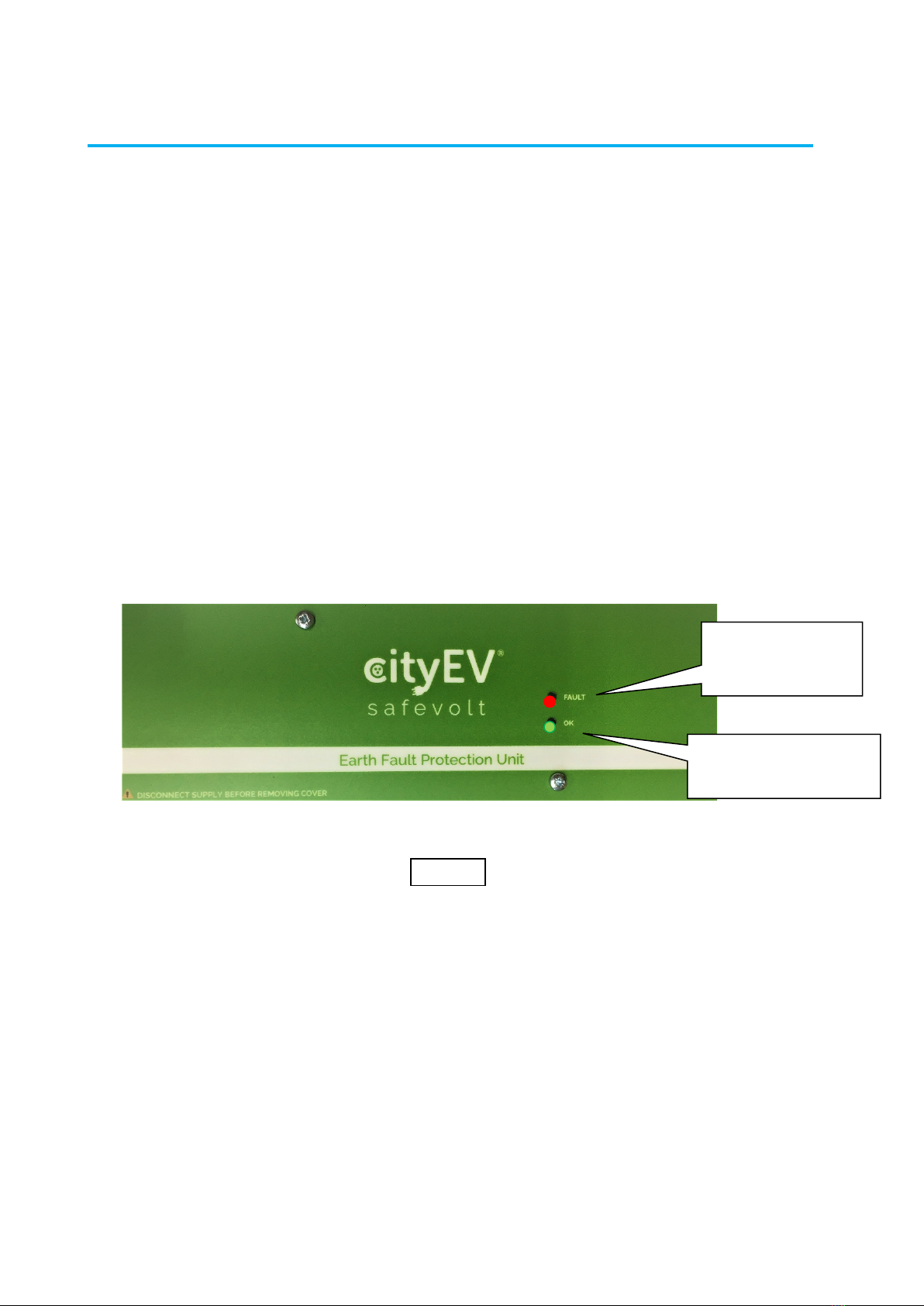
Safevolt® 50 Operation
The Safevolt® 50 status indicators are shown and described below.
During normal operation, the green OK LED will show a steady green indicating that the output is on and
the charge point is connected.
If a PME fault condition is detected the red FAULT indicator will light and the charge point will be
disconnected from the L, N and E conductors, the Green OK LED will be off indicating that the output is
isolated.
When the PME fault is rectified the unit will automatically reconnect the charge point.
CityEV Safevolt 50 User and Installation Manual
OUTPUT (OK) LED,
Steady green when output
is ON
FAULT LED
ON when PME fault
detected.
Output is isolated.
Cityline Safevolt 50 User and Installation Manual
CityEV Safevolt® 50 User and Installation Manual
Figure 1
Page 6
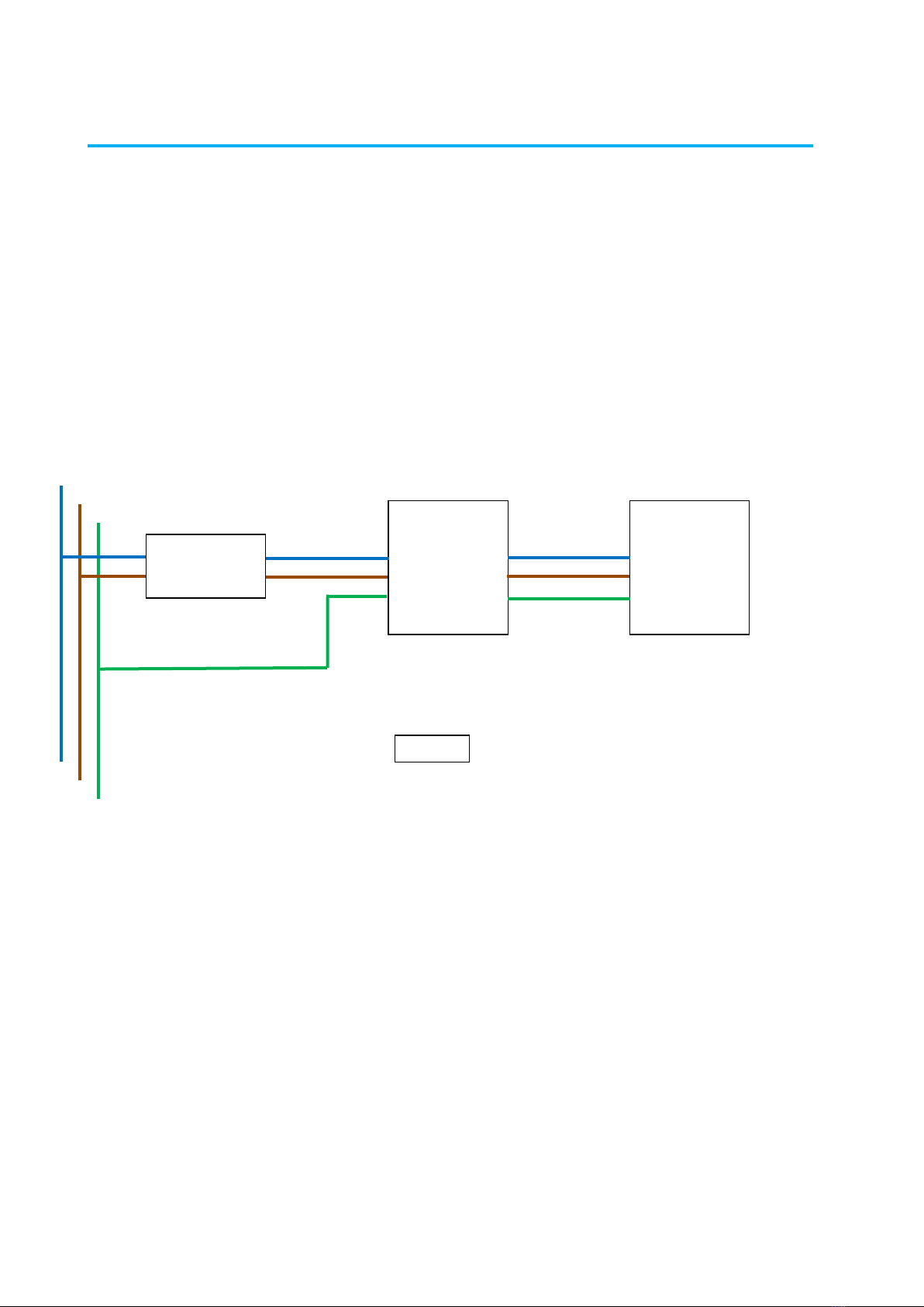
Safevolt®50 Installation
The CityEV Safevolt 50 unit is installed between the charge point supply and the charge point itself in
series with the live, neutral and earth conductors.
⚠The Safevolt® 50 unit is not weather protected and intended for indoor installation only.
Figure 2 below shows typical single-phase charge point installation using the Safevolt®50 protection unit.
Safevolt® 50 single phase installation
Safevolt®50
N N
L L
E E
Chargepoint
N
L
E
Double pole
Type A RCD
Supply
Cityline Safevolt 50 User and Installation Manual
CityEV Safevolt® 50 User and Installation Manual
Figure 2

Page 7
Positioning
⚠The Safevolt® 50 unit is intended to be wall mounted in an indoor location as the unit is not weather
protected.
For cable entry, two 20mm cut-outs are provided, one on the input side and one on the output side of the
unit. A 20mm cable gland should be inserted into the cut-outs of the type appropriate to the cable used,
e.g. flat T&E, round or SWA types. Ensure cables are securely secured by glands or use cable ties if
necessary.
Electrically the unit is connected in series with the charge point supply.
Removing the cover
⚠Ensure that the unit is isolated from power before the cover is removed
The cover is removed by removing the two front panel screws and sliding the front cover off towards the
operator as shown:
Cityline Safevolt 50 User and Installation Manual
Remove Screw
Remove Screw
CityEV Safevolt® 50 User and Installation Manual
Figure 3

Page 8
Connections
Connecting the unit is straight forward. The incoming supply including the CPC is connected to the left-
hand lever connectors and the outgoing supply to the charge point is connected to the right-hand lever
connectors as shown:
Note: Maximum cable size is 6mm2
CityEV Safevolt® 50 User and Installation Manual
Supply N
Supply E
N to CP
E to CP
Supply L
L to CP
Figure 4

Page 9
Electrical Testing
If performing a Zs test at the charge point, the Safevolt 50 will need to be installed and operational and
the green output LED ON.
If the Safevolt®50 is not operational the CPC will be disconnected from the charge point and the Zs test
will fail.
For insulation testing, L, N & E should be disconnected from the input of the Safevolt®50.
Insulation testing will require the circuit to the charge point to be tested in two segments, i.e. supply to
Safevolt 50 and then Safevolt 50 to Chargepoint.
For each segment the Safevolt®50 should be disconnected from the segment under test and in the case of
Safevolt®50 to Chargepoint, the charge point disconnected also.
Precautions
General
The Safevolt®50 unit is designed to isolate the installation PME earth from the charge point CPC in the
event of a PEN conductor (PME) failure.
⚠It is therefore important to check that no part of the CPC circuit on the output side of the Safevolt®50
unit is connected to any point which is directly or indirectly connected back to the building earth.
Any such connections will render the Safevolt®50 system ineffective.
For instance, check no secondary earth connection exists between the casing of the charge point and any
metallic part such as a DB casing or service pipe.
Special care is needed if using SWA cables as described on the next page.
Cityline Safevolt 50 User and Installation Manual
Cityline Safevolt 50 User and Installation Manual
CityEV Safevolt® 50 User and Installation Manual

Page 10
Using SWA cables with Safevolt® 50
⚠For the reasons given above, if using SWA cable between the Safevolt®50 unit and the charge point or
the supply DB and the Safevolt it is important to verify that the SWA amour termination will not result in a
connection between the building CPC and the charge point CPC including the metal case of the Safevolt
unit. For instance, an SWA cable terminated in the charge point case and a building DB with a metallic
case will cause such a connection and is not allowed.
Chargepoint
E
Metal
Distribution
Board
Safevolt 50
SWA
CABLE
Chargepoint
E
Metal
Distribution
Board
Safevolt 50
SWA
CABLE
Figure 5
Non
SWA
CABLE
Chargepoint
E
Metal
Distribution
Board
SWA
CABLE
Non-Metal
Termination
Box Safevolt 50
SWA
CABLE
SWA
CABLE
CityEV Safevolt® 50 User and Installation Manual

Page 11
Safevolt® 50 Specifications
Operating Parameters
Supply Voltage Range (AC) 205-260V
Maximum Load Current 32A
Earth Fault Isolation 3 pole - L, N, E
Earth Fault Trip Delay 4 Seconds
Earth Fault Trip Reset Automatic
Connectors Screw Terminal Max 6mm2
Indicators
•Output On
•PME Earth Fault
Dimensions
Wall mounting 200mm W x 70mm H x 50mm D
Weight 750g
Environmental
Operating Temperature: -20oC to +45oC
Operating Humidity: 95% RH
Indoor Installation Only: IP 52
Cityline Safevolt 50 User and Installation Manual
CityEV Safevolt® 50 User and Installation Manual

Page 12
EC Declaration of Conformity In accordance with 768/2008/EC
We CityEV Ltd. of Technopole, Kingston Crescent, Portsmouth, UK. PO2 8FA
In accordance with the following Directives:
2014/35/EU - The Low Voltage Directive
2004/108/EC The Electromagnetic Compatibility Directive;
Hereby declare that: Equipment: Earth Fault Protection Equipment - Safevolt50
Is in conformity with the applicable requirements of the following documents:
Ref. No. Title
BS EN 61000-6-1 Electromagnetic compatibility (EMC).
Generic standards. Immunity for residential,
commercial & light-industrial environments 2007
BS EN 61000-6-3 Electromagnetic compatibility (EMC).
Generic standards. Emission standard for
residential, commercial & light-industrial
environments 2007
EN 61000-3-2 Electromagnetic compatibility (EMC), 2014
Part 3-2 - Limits; Limits for harmonic current emissions
EN 60335-1 household and similar electrical appliances. Safety, 2012
part 1: general requirements
BS 7671 Fully compliant with section 722.411.4.1 (iv), 2018
(Electric vehicle charging installations, TN systems)
I hereby declare that the equipment named above is compliant with the relevant sections of the above referenced
specifications. The unit complies with all applicable Essential Requirements of the Directives.
Name: R Morris, CTO,
Date: 21st August 2020
CityEV Ltd. 2020
Documents may include an extract taken from the IET Standards Code of Practice for Electric Vehicle Charging Equipment Installation 3rd Edition;
note that this is their copyright material and is acknowledged; the extract is for the illustration of the IET recommendations only, in the
commercial interests of improving safety and compliance; the CityEV Safevolt® 50 is a commercial product with relevant CityEV trademarks and
patent applications and has no connection with any organisation outside CityEV Ltd. and is not specifically endorsed by any other organisation.
CityEV designs are covered by one or more patent applications. The CityEV logos are registered trademarks.
Information is corect at the time of writing and will be updated in line with development is the relavant standards and regulations.
CityEV Helpline: 02393 190109 support@cityev.net
Table of contents
Popular Power Distribution Unit manuals by other brands

Eaton
Eaton Power Xpert PXR 20 user manual

ICT
ICT ICT180S-12IRC instruction manual

brennenstuhl
brennenstuhl Professional BSV 5 5/4 N5160 AT operating instructions

Scame electrical solutions
Scame electrical solutions OPTIMA-EX 16-32-63A INSTRUCTIONS ON INSTALLATION, USE AND MAINTENANCE

LEGRAND
LEGRAND HPM Electresafe REPC410 instruction manual

Woodward
Woodward HighPROTEC MRU4-2 G Series manual


