EnerSys alpha CXDM-E3 400A User manual

CXDM-E3 400A
Distribution Module
Technical Guide: 9400014-J0
Effective: 10/2019


CXDM-E3 Distribution Module
Models: 400A
For technical support, contact Alpha Technologies:
Canada and USA: 1-888-462-7487
International: +1-604-436-5547
Copyright
Copyright © 2019 Alpha Technologies Ltd. All rights reserved. Alpha is a registered trademark of Alpha Technolo-
gies.
No part of this documentation shall be reproduced, stored in a retrieval system, translated, transcribed, or transmit-
ted in any form or by any means manual, electric, electronic, electromechanical, chemical, optical, or otherwise
without prior explicit written permission from Alpha Technologies.
This document, the software it describes, and the information and know-how they contain constitute the proprietary,
confidential and valuable trade secret information of Alpha Technologies, and may not be used for any unauthorized
purpose, or disclosed to others without the prior written permission of Alpha Technologies.
The material contained in this document is for information only and is subject to change without notice. While
reasonable efforts have been made in the preparation of this document to assure its accuracy, Alpha Technologies
assumes no liability resulting from errors or omissions in this document, or from the use of the information contained
herein. Alpha Technologies reserves the right to make changes in the product design without reservation and with-
out notification to its users.
Alpha shall not be held liable for any damage or injury involving its enclosures, power
supplies, generators, batteries, or other hardware if used or operated in any manner or
subject to any condition inconsistent with its intended purpose, or if installed or oper-
ated in an unapproved manner, or improperly maintained.
Photographs contained in this manual are for illustrative purposes only. These photo-
graphs may not match your installation.
NOTE:
Operator is cautioned to review the drawings and illustrations contained in this manual
before proceeding. If there are questions regarding the safe operation of this powering
system, contact Alpha Technologies or your nearest Alpha representative.
NOTE:
NOTE:


39400014-J0 Rev. C
Table of Contents
1. Safety....................................................................................................................................5
1.1 Safety Symbols .......................................................................................................................... 5
1.2 General Safety ........................................................................................................................... 5
1.3 Mechanical Safety...................................................................................................................... 5
1.4 Electrical Safety ......................................................................................................................... 6
1.5 Battery Safety ............................................................................................................................ 6
2. Introduction ...........................................................................................................................7
2.1 Scope of the Manual .................................................................................................................. 7
2.2 Product Overview....................................................................................................................... 7
2.3 Module Congurations ............................................................................................................... 8
3. Specications........................................................................................................................9
4. Features..............................................................................................................................10
4.1 Product Overview..................................................................................................................... 10
4.2 Standard Front Panel............................................................................................................... 12
4.3 Front Panel with Enhanced I/O ................................................................................................ 13
4.4 LVD Override ........................................................................................................................... 14
5. Inspection............................................................................................................................16
5.1 Packing Materials..................................................................................................................... 16
5.2 Check for Damage ................................................................................................................... 16
5.3 General Receipt of Shipment................................................................................................... 16
6. Installation...........................................................................................................................17
6.1 Safety Precautions................................................................................................................... 17
6.2 Tools Required ......................................................................................................................... 17
6.3 Installation of External Batteries .............................................................................................. 18
6.4 Battery Maintenance Report .................................................................................................... 19
6.5 Breaker Installation .................................................................................................................. 20
7. Wiring..................................................................................................................................21
7.1 Installation Notes ..................................................................................................................... 21
7.2 Grounding ................................................................................................................................ 22
7.3 DC Wiring................................................................................................................................. 23

9400014-J0 Rev. C
4
7.4 Distribution Cabling.................................................................................................................. 24
7.5 Alarm and Signal Connection (Interface Board)....................................................................... 25
7.6 Signal Wiring (L-ADIO) ............................................................................................................ 26
8. System Startup ...................................................................................................................27
9. Maintenance .......................................................................................................................28
10. Acronyms and Denitions .................................................................................................29
11. Warranty and Service Information.....................................................................................30
11.1 Technical Support................................................................................................................... 30
11.2 Warranty Statement ............................................................................................................... 30
11.3 Limited Hardware Warranty.................................................................................................... 30
11.4 Battery Warranty .................................................................................................................... 30
11.5 Warranty Claims..................................................................................................................... 30
11.6 Service Centers...................................................................................................................... 30
12. Certication.......................................................................................................................31
List of Figures
Figure 1 — Front view of the CXDM-E3 ........................................................................................... 7
Figure 2 — 19" CXDM-E3................................................................................................................. 8
Figure 3 — 23" CXDM-E3................................................................................................................. 8
Figure 4 — Standard front panel..................................................................................................... 12
Figure 5 — Left-side Connections .................................................................................................. 12
Figure 6 — Right-side Connections ................................................................................................ 12
Figure 7 — L-ADIO I/O Peripheral .................................................................................................. 13
Figure 8 — LVD Override................................................................................................................ 14
Figure 9 — LVD Override Interface................................................................................................. 14
Figure 10 — LVD Override Connections......................................................................................... 15
Figure 11 — Breaker Installation..................................................................................................... 20
Figure 12 — Connecting the frame ground..................................................................................... 23
Figure 13 — Alarm (Relay) connections ......................................................................................... 25
Figure 14 — Digital input connection method ................................................................................. 25
Figure 15 — Alarm relay pinouts..................................................................................................... 26

59400014-J0 Rev. C
1. Safety
SAVE THESE INSTRUCTIONS: This manual contains important safety instructions that must
be followed during the installation, servicing, and maintenance of the product. Keep it in a safe place. Review the
drawings and illustrations contained in this manual before proceeding. If there are any questions regarding the safe
installation or operation of this product, contact Alpha Technologies or the nearest Alpha representative. Save this
document for future reference.
1.1 Safety Symbols
To reduce the risk of injury or death, and to ensure the continued safe operation of this product, the following sym-
bols have been placed throughout this manual. Where these symbols appear, use extra care and attention.
The use of ATTENTION indicates specic regulatory/code requirements that may aect the
placement of equipment and /or installation procedures.
WARNING!
WARNING presents safety information to PREVENT INJURY OR DEATH to personnel.
Warnings are indicated by a shock hazard icon, the word WARNING, and a rule beneath
which the information appears.
CAUTION!
CAUTION indicates safety information intended to PREVENT DAMAGE to material or
equipment. Cautions are designated with a yellow warning triangle, the word CAUTION,
and a rule beneath which the information appears.
NOTE:
A NOTE provides additional information to help complete a specic task or procedure.
Notes are designated with a check mark, the word NOTE, and a rule beneath which the
information appears
HOT!
HOT symbol indicates safety information to PREVENT BURNS to the technician or user.
1.2 General Safety
WARNING!
This system is designed to be installed in a restricted access location that is inacces-
sible to the general public.
1.3 Mechanical Safety
• Keep hands and tools clear of fans. Fans are thermostatically controlled and switch on automatically.
• Power supplies can reach extreme temperatures under load.
• Use caution around sheet metal components and sharp edges.

9400014-J0 Rev. C
6
1.4 Electrical Safety
WARNING!
WARNING!
WARNING!
• Before working with any live battery or power system, follow these precautions:
a. Remove all metallic jewelry, such as watches, rings, metal rimmed glasses, or necklaces.
b. Wear safety glasses with side shields at all times during the installation.
c. Use OSHA approved insulated hand tools.
Lethal voltages are present within the power system. Always assume that an electrical
connection or conductor is energized. Check the circuit with a voltmeter with respect to
the grounded portion of the enclosure (both AC and DC) before performing any installa-
tion or removal procedure.
• Do not work alone under hazardous conditions.
• A licensed electrician is required to install permanently wired equipment. Input voltages can range up to 277 Vac.
Ensure the utility power is disconnected and locked out before performing any installation or removal procedure.
• Ensure that no liquids or wet clothes come into contact with internal components.
• Hazardous electrically live parts inside this unit are energized from the batteries even when the AC input power is
disconnected.
Follow battery manufacturer’s safety recommendations when working around battery systems. Do not
smoke or introduce an open ame when batteries (especially vented batteries) are charging. When charg-
ing, batteries vent hydrogen gas, which can explode.
• Batteries are hazardous to the environment and should be disposed at a recycling facility. Consult the battery
manufacturer for recommended local authorized recyclers.
Hazardous voltages are present at the input of power systems. The DC output from rec-
tiers and batteries, though not dangerous in voltage, has a high short-circuit current
capacity that may cause severe burns and electrical arcing.
WARNING!
HIGH LEAK CURRENT. Earth connection is essential before connecting the supply.
CAUTION! and HOT!
Internal DC breakers can be hot surfaces. Use a bullet socket removal tool for removal
of circuit breakers.
1.5 Battery Safety
• Servicing and connection of batteries must be performed by, or under the direct supervision of, personnel knowl-
edgeable of batteries and the required safety precautions.
• Always wear eye protection, rubber gloves, and a protective vest when working near batteries. Remove all metal-
lic objects from your hands and neck.
• Use OSHA approved insulated hand tools. Do not rest tools on top of batteries.
• Batteries contain or emit chemicals known to cause cancer and birth defects or other reproductive harm. Battery
post terminals and related accessories contain lead and lead compounds. Wash your hands after handling bat-
teries.

79400014-J0 Rev. C
2. Introduction
2.1 Scope of the Manual
This manual covers the features, options, installation and startup of Alpha Technologies CXDM-E3 distribution mod-
ule. To assist with installation reference may be made to the drawings at the rear of this manual.
2.2 Product Overview
Alpha's E3 is a front access distribution center, available with the L-ADIO expanded I/O module, is the ideal solution
for small to medium-sized 48Vdc or 24Vdc applications, handling up to 400 Amps of output current. With 23" or uni-
versal 19"/23" widths, high temperature operation and high power density, it is the perfect solution for a wide variety
of installation scenarios. The distribution center provides up to 26 load breaker positions, integrated shunt and LVD.
All distribution connections and controller I/O contacts are front accessible.
The E3 can be easily integrated into customer-provided relay racks or enclosures, or can be ordered factory installed
into various Alpha relay rack configurations, including systems with pre-wired battery trays.
• 400A, 26 distribution positions in 3RU size
• Industry leading power system density
Figure 1 — Front view of the CXDM-E3
9400014-J0 Rev. C
8
2.3 Module Configurations
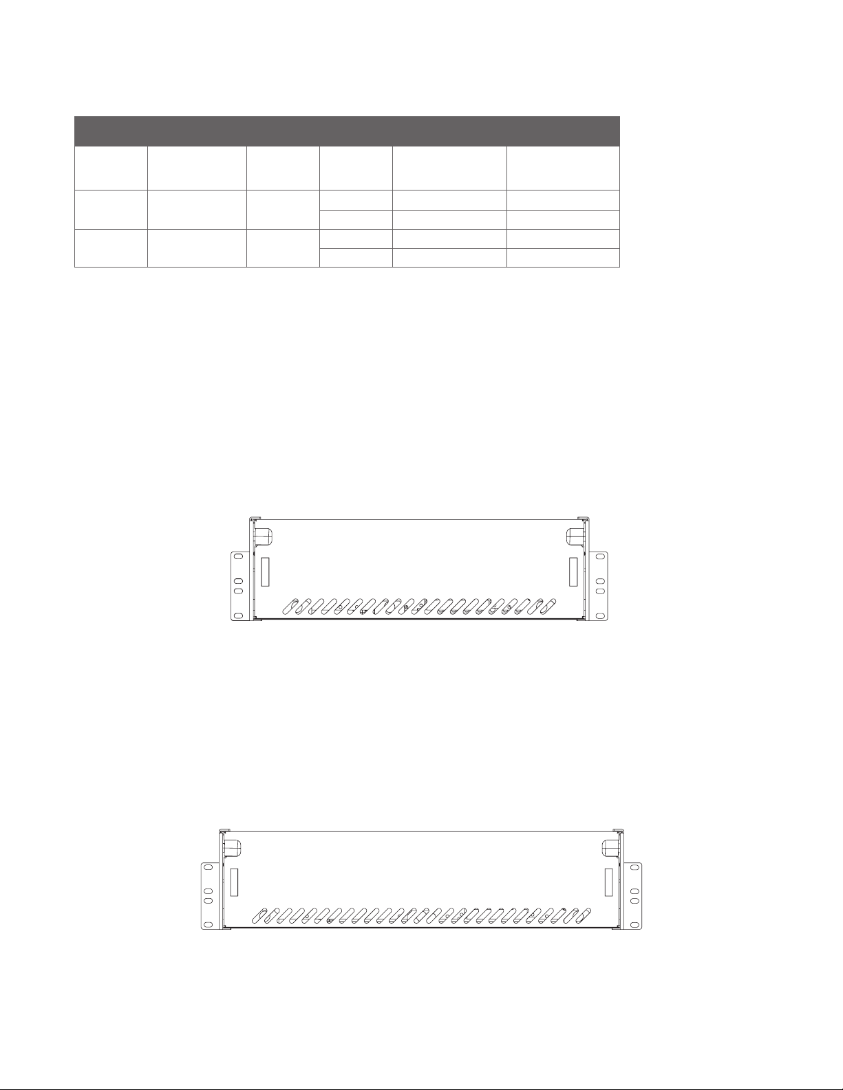
The following four configurations are currently available for the CXDM-E3 distribution module.
CXDM-E3 Conguration Table
Rack Size Expanded I/O
(Optional)
Current
Rating
Load
Breakers
Low Voltage
Load Disconnect
Height
19" L-ADIO 400A 21 Yes 3RU
21 No 3RU
23" L-ADIO 400A 26 Yes 3RU
26 No 3RU
2.3.1 CXDM-E3 19"/23" Distribution Module
• Rated for 400A
• 3RU
• 21 load breakers with load shunt or 21 load breakers with load shunt and LVLD
• Option for L-ADIO board for expanded I/O capability
REVISIONS
LTR
DESCRIPTION
DWN
DATE
CHK
B
C
D
E
3
4
5
D
A
C
E
B
13
542
DO NOT SCALE DRAWING
Figure 3 — 23" CXDM-E3
2.3.2 CXDM-E3 23" Distribution Module
• Rated for 400A
• 3RU
• 26 load breakers with load shunt or 26 load breakers with load shunt and LVLD
• Optional L-ADIO module with expanded I/O capability
Figure 2 — 19" CXDM-E3
REVISIONS
LTR
DESCRIPTION
DWN
DATE
CHK
B
C
D
E
3
4
5
D
A
C
E
B
13
542
DO NOT SCALE DRAWING

99400014-J0 Rev. C
3. Specifications
Table A — Specications CXDM-E3 400A
Mechanical
19"
System
Mounting Flush/Center
Dimensions 5.25"H x 19"W x 17.4"D
Hot Positions 21x Load Breakers
21x sets of 1/4" Studs on 5/8" Centers
Return Positions 21x sets of 1/4" Studs on 5/8" Centers
Weight (System) 31lbs
23"
System
Mounting Flush/Center
Dimensions 5.25"H x 23"W x 17.4"D
Hot Positions 26x Load Breakers
26x sets of 1/4" Studs on 5/8" Centers
Return Positions 26x sets of 1/4" Studs on 5/8" Centers
Weight (System) 37lbs
System Access Front access after initial installation
Environmental
Temperature: natural convection
cooled (rack application) -40 to 65°C (-40 to 149°F)
Humidity 0 to 95% RH non-condensing
Elevation -500 to 4000m (-1640 to 13100ft)
Compliance
Safety CSA C22.2 No. 60950-1
UL 60950-1

9400014-J0 Rev. C
10
4. Features
4.1 Product Overview
4.1.1 Distribution Center Configurations
The E3 distribution has been designed with high density breaker/fuse count for use in ±48Vdc or ±24Vdc applica-
tions with a total ampacity of 400A. It is available either in a 19" or 23" configuration. All systems include a rear top
polycarbonate cover for the protection of live customer connections.
4.1.2 19" Distribution Module
Provides up to 21 breakers which is configured as all load breakers (21 load breakers).
The all load breaker configurations have a shunt that monitors the total load current supplied by the rectifiers to the
load and has an option for a 600A Low Voltage Load Disconnect (LVLD).
Automatic control of the LVLD can be bypassed using the LVD override feature when necessary such as during
maintenance intervals.
Load hot and return connections are made on 1/4" studs on 5/8" centers using narrow tongue lugs. Adapter kits for
landing larger cables are available when higher capacity 2 or 3 pole breakers are required.
4.1.3 23" Distribution Module
Provides up to 26 breakers which is configured as all load breakers (26 load breakers).
The all load breaker configuration has a shunt that monitors the total load current supplied by the rectifiers to the
load and has an option for a 600A Low Voltage Load Disconnect (LVLD).
Both the hot and return connections are made on 1/4" studs on 5/8" centers using narrow tongue lugs. Adapter kits
for landing larger cables are available when higher capacity 2 or 3 pole breakers are required.
4.1.4 Control and Monitoring Methods
The E3 is available with two different front panels that provide increasing levels of inputs and outputs (I/O). Either
connector breakouts for I/O or enhanced I/O interface with CAN Bus connectivity. All panels have the basic features
such as, alarm indicators, door latches, and top label as shown in Figure 4.
The standard front panel includes two indicator circuit boards, one for each bus located at the corresponding end
of the panel. Each indicator board receives power and signals through a single cable which connects to the breaker
alarm strip in the core of the E3. The indicator boards also act as an interface to the L-ADIO module in the more
advanced panel version.

119400014-J0 Rev. C
Feature Standard CAN Bus Monitoring
LED indicator – Bus Power Present/Breaker
Alarm (2
• •
Dry Contact– Breaker Alarm (2) • •
Bus Voltage Sense (2) • •
Dedicated I/O:
Bus Voltage Monitoring (2)
Breaker Alarm Monitoring (2)
•
Expansion I/O (Customer Use):
Temperature Sensor Inputs (4)
Form C Relay Outputs (12)
Digital Inputs (6)
Voltage Sense Inputs (2)
Current Shunt Inputs (4)
•
4.1.5 Breaker Labelling
For systems the numbering goes from left (1) to right (21) for a 19" or (26) for a 23"
There is a label on top of the front door which can be seen from the top when the door is closed, and from the front
when the door is open. This label is larger and suitable for writing information about the breaker position.
There are two additional labels for breaker identification: a thin label above the breaker which can be read from the
front (not writable), and one on the back/top near the return breakers which identify the positions of the return (not
writable)
9400014-J0 Rev. C
12
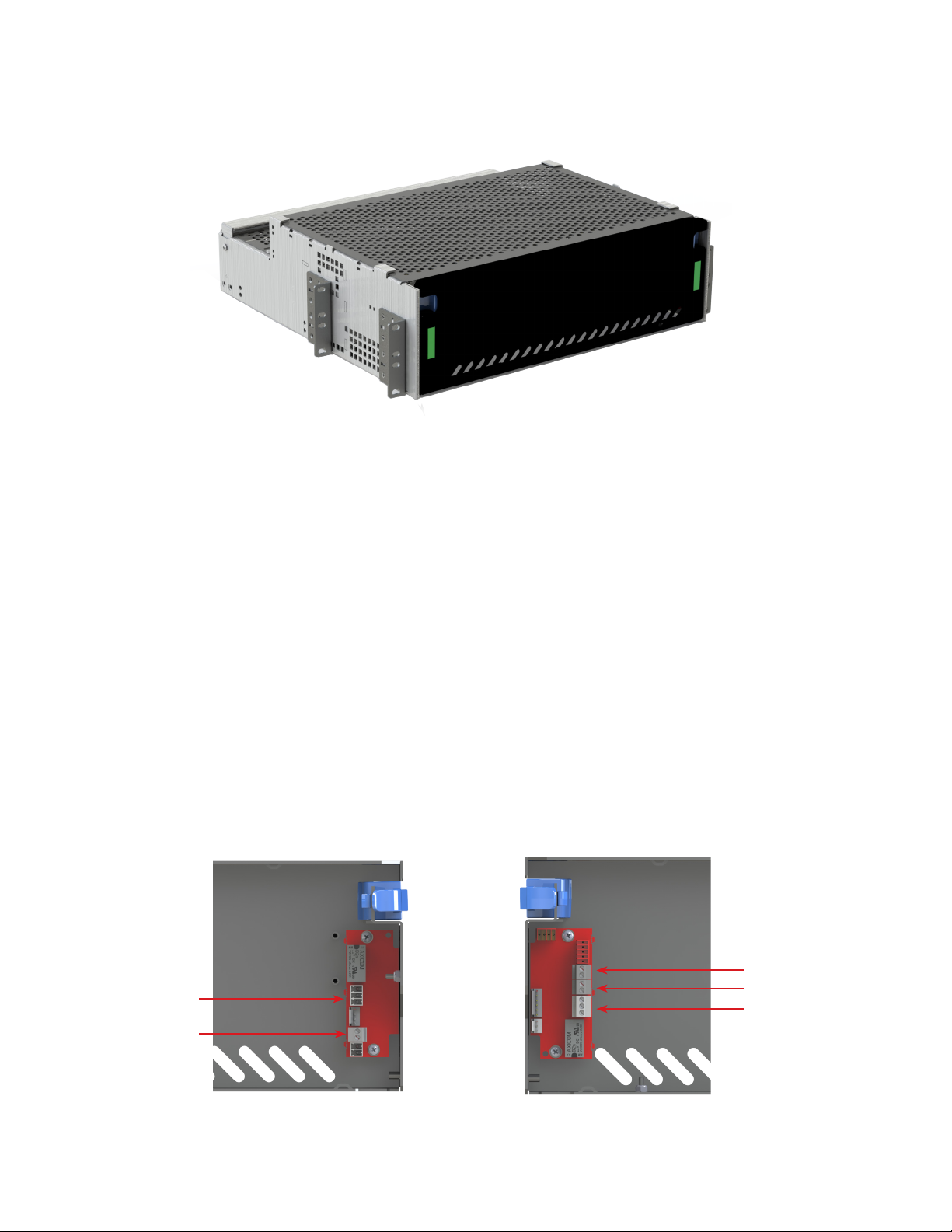
4.2 Standard Front Panel
Figure 4 — Standard front panel
4. 2.1 Status Indicators
All E3 front panels have two LED indicators that indicate the breaker status for each bus. On single bus (load only)
systems, both indicators are green when the bus is powered and turn red when any breaker trips.
4.2.2 Basic Status Outputs
Each indicator board has two terminal block connectors that provide connections to a Form C dry contact for the
breaker alarm, and to connect. The right-hand board has terminals for monitoring bus voltage, which can be wired
to 3rd party monitoring equipment. The left-hand board has current sense. The terminal blocks can be accessed
when the door is open.
This is a non-isolated fused signal intended for connection to a high impedance input. A three-position screw type
terminal connector makes the breaker status available through connection to a dry contact relay.
Output signals, current sense, voltage sense *for each bus, breaker alarm *for each bus.
Refer to the customer connection drawings at the back of this manual for PIN outs.
Figure 5 — Left-side Connections Figure 6 — Right-side Connections
Breaker Alarm B
Voltage Bus A
Voltage Bus B
Breaker Alarm A
Current Sense

139400014-J0 Rev. C
4.3 Front Panel with Enhanced I/O
The front panel with enhanced I/O includes the components and functionality of the standard front panel with the
addition of a Large Analog /Digital Input and Output (L-ADIO) module and a cable harness that connects it to the in-
dicator boards. The L-ADIO module is powered by both the A and B bus via the indicator boards and will continue to
operate even if one of the bus is not powered. The breaker alarm status and voltage level of each bus is monitored
by the L-ADIO and can be read by a remote CXC HP controller through the CAN bus connection.
The L-ADIO also provides expansion I/O capability, including two analog voltages (V3-V4), four thermocouples (T1-
T4), 12 dry contact relays (K1-K12), six digital inputs (D3-D8). Please refer to the hardware manual (0180036-J0) for
specifications of these inputs, as well as the front panel wiring notes below for guidance on L-ADIO wire routing.
Figure 7 — L-ADIO I/O Peripheral
4.3.1 Analog Input Channels
The controller is supplied with analog input channels for voltage, current, and temperature.
4.3.2 Voltage Inputs
Two voltage input channels, V1 and V2, are used to monitor the discharge and charge voltage. V1 for Bus A Voltage
and V2 for Bus B Voltage. Voltage inputs V3 and V4 are not used in the E3 and are available for customer use.
4.3.3 Temperature Inputs
The E3 panel can accept up to four temperature probes to monitor the surrounding ambient temperatures. These
analog values can be used to report high or low temperature alarms.
4.3.4 Digital Input Channels
The E3 panel can accept up to eight digital inputs. Digital Inputs D1 and D2 are wired for Bus 'A' Breaker Alarm and
Bus 'B' Breaker Alarm respectively. Digital inputs D3 to D8 are available for customer use.
CAN Ports
CAN Ports
Power Input Bus B Alarm
Bus B Voltage
Bus A Alarm
Bus A Voltage

9400014-J0 Rev. C
14
4.3.5 Alarm and Control Output Relays
The controller contains 12 Form C digital alarm output relays, that are used to extend alarms and control to external
apparatus. Each internally generated alarm or control signal may be mapped to any one of these relays, or several
signals may be mapped to just one relay or none at all. None of the output relays are pre-configured on the (K1-K12)
are available for customer use.
4.3.6 Network Connection and Remote Communication
A CAN bus is used to transmit all alarm and control functions between the L-ADIO and a remotely located CXC HP
controller.
4.4 LVD Override
For systems with LVLD, an over-ride interface is provided, see Figure 8 and Figure 9. This interface board includes 3
LEDs indicators to provide visual status indication, and two customer connections for remote control/monitoring:
LEDs
• BUS (Green) Lit when the bus connected to the LVD has power connected.
• COIL (Green) Lit when the LVD coil is energized. This requires the BUS to have power and one of the controls
(L-ADIO, REMOTE, or LVD Over-ride) to be active
• O/R (Yellow) Lit when the override switch is in the over-ride position. This should only be on during maintenance.
Connections
• OVERRIDE 48V/5mA or 24V/5mA signal, active when over-ride switch is in over-ride position.
» COIL CTRL Control input for LVBD/LVLD coil, can be configured for remote control or remote disable:
When configured for remote control (default), a dry contact connected to the coil control input can turn
on the LVLD independently of the LVD or the automatic control.
» When configured for remote disable, the coil control input must be shorted by a dry contact for either
the automatic control or the LVD override to operate.
The LVLD override interface is configured for remote control by default for most systems.
Figure 8 — LVD Override
Figure 9 — LVD Override Interface

159400014-J0 Rev. C
SCALE:
REV
SHEET
SIZE
DWG NO.
TITLE:
OF
A
1:1
B
2 4
0919XXX-XXX-08
CUSTOMER CONNECTION,
CXPS, 19" & 23"
AUTO
OVERRIDE
BUS POWER
(GREEN)
LVD COIL POWER
(GREEN)
OVERRIDE ACTIVE
(YELLOW)
SW1
L-ADIO / CXC HP
POWER
LVD
L-ADIO I/O
CTRL (NO)
ENABLE (NC)
STATUS LEDS
LVD COIL CONTROL (COM)
LVD COIL CONTROL (HOT)
LVD OVERRIDE SWITCH STATE (-)
LVD OVERRIDE SWTICH STATE (+)
LVD OVERRIDE SWITCH
TB2 TB1
DS1
DS2
DS3
LVD OVERRIDE BOARD
CUSTOMER CONNECTIONS
FACTORY CONNECTIONS
COIL CONTROL JUMPER
DO NOT SCALE DRAWING
2
4
53 1
B
E
C
A
D
543 2 1
E
D
C
B
A
To change configuration:
This operation must be done with DC power disconnected, ideally prior to commissioning the system.
1. Remove the interface from the E3 by removing the two (2) screws from the front
2. Lower the board, and pull it forward through the opening.
3. Flip the board over, and observe the jumper on the bottom of the board.
4. Move the jumper to the desired position:
» CTRL (NO) position: the COIL CTRL is configured for remote control
» ENBL (NC), COIL CTRL for remote enable.
5. After the jumper is set check all cable connections (in case they were pulled loose when the board was
removed)
6. Reinstall the board and labels using the original screws.
Figure 10 — LVD Override Connections

9400014-J0 Rev. C
16
5. Inspection
5.1 Packing Materials
Alpha is committed to providing products and services that meet our customers’ needs and expectations in a sus-
tainable manner, while complying with all relevant regulatory requirements. As such Alpha strives to follow our quality
and environmental objectives from product supply and development through to the packaging for our products.
Rectifiers and batteries are shipped on individual pallets and are packaged according to the manufacturer’s guidelines.
Almost all of Alpha’s packaging material is from sustainable resources and/or is recyclable. See the following table
for the material and its environmental codes.
5.1.1 Returns for Service
Save the original shipping container. If the product needs to be returned for service, it should be packaged in its
original shipping container. If the original container is unavailable, make sure that the product is packed with at least
three inches of shock-absorbing material to prevent shipping damage. Alpha Technologies is not responsible for
damage caused by improper packaging of returned products.
5.2 Check for Damage
Prior to unpacking the product, note any damage to the shipping container. Unpack the product and inspect the ex-
terior for damage. If any damage is observed contact the carrier immediately. Continue the inspection for any internal
damage. In the unlikely event of internal damage, inform the carrier and contact Alpha Technologies for advice on
the impact of any damage.
5.3 General Receipt of Shipment
The inventory included with your shipment is dependant upon the options you have ordered. The options are clearly
marked on the shipping container labels and bill of materials.
5.3.1 Racks
Consult the packing slip and power system bill of materials to verify that you have the correct number of racks per
your order.
5.3.2 Rectifiers (Purchased Separately)
Consult the packing slip to verify that you have received the correct number of rectifiers per your order.
5.3.3 Miscellaneous Small Parts
Review the packing slip and bill of materials to determine the part number of the “configuration kits” included with
your system. Review the bill of materials to verify that all the small parts are included.
5.3.4 Batteries (Purchased Separately)
Verify that you have the correct number of batteries if applicable. Refer to the packing list. Verify that you have all the
necessary parts per your order.
Call Alpha Technologies if you have any questions before you proceed: 1 888 462-7487.
Cardboard Polyethylene
Terephthalate
Low Density
Polyethylene
Polystyrene Steel Aluminum Wood
Packing boxes
Caps
Flexible film
Packaging
Bubble wrap
Shrink wrap
Plastic bags
Foam Strapping on
pallets
Strapping on
pallets
Pallets
Lumber

179400014-J0 Rev. C
6. Installation
Only qualified personnel should install and connect the power components within the Alpha power system. For the
battery installation, refer primarily to the manufacturer’s manual.
Frequent reference is made to drawings located at the rear of this manual.
6.1 Safety Precautions
Refer to the Safety section near the front of this manual.
6.2 Tools Required
Various insulated tools are essential for the installation. Use this list as a guide:
• Battery lifting apparatus if required
• Electric drill with hammer action, 1/2" capacity
• Various crimping tools and dies to match lugs used in installation
• Load bank of sufficient capacity to load largest rectifier to its current limit
• Digital voltmeter equipped with test leads
• Cable cutters
• Torque wrench: 1/4" drive, 0 - 150 in-lb
• Torque wrench: 3/8" drive, 0 - 100 ft-lb
• Insulating canvases as required (2' x 2', 1' x 1', 3' x 3', etc.)
• Various insulated hand tools including:
- Combination wrenches
- Ratchet and socket set
- Various screwdrivers
- Electricians knife
• Battery safety spill kit required for wet cells only:
- Protective clothing
- Face shields
- Gloves
- Baking soda
- Eye wash equipment
• Cutters and wire strippers (#14 to #22 AWG) [2.5 to 0.34 mm²]

9400014-J0 Rev. C
18
WARNING!
6.3 Installation of External Batteries
This information is provided as a guideline and is not meant to imply that batteries are part of this power system.
Follow the battery manufacturer’s safety recommendations when working around bat-
tery systems and review the safety instructions provided in this manual.
Batteries should be located in a temperature-controlled environment, regulated to approximately 25°C (77°F). Signifi-
cantly lower temperatures reduce performance and higher temperatures decrease life expectancy.
Provide adequate ventilation. VRLA batteries, though not requiring the special ventilation requirements of a flooded
battery, should not be installed in an airtight enclosure. Hydrogen gas can be emitted from a failed battery.
If applicable, clean the cells before assembly according to the battery manufacturer's recommendations. First neu-
tralize any acid with a baking soda and water solution; then wipe the cells with clean water.
6.3.1 Installation
Verify that all battery breakers, DC circuit breakers, and fuses on the distribution panels are either in the OFF position
or removed.
Apply a corrosion-inhibiting agent, such as NO-OX-ID "A", on all battery terminal connections.
1. If required, assemble the battery rack and the cells or mono-blocks as per the installation instructions supplied
with the batteries.
2. Ensure that the battery output cabling can reach the [+] and [–] terminals of the series battery string and that the
batteries are oriented correctly for easy installation of the inter-unit "series" connectors.
3. Remove any NO-OX-ID "A" grease from battery terminals.
4. Burnish the terminal posts with a non-metallic brush, polishing pad or 3M Scotch Brite scouring pad.
5. Apply a light coating of NO-OX-ID "A" grease to the terminal posts.
6. If lead plated inter-unit connectors are used, they should also be burnished and NO-OX-ID "A" grease applied as
above. Install the inter-unit connectors.
7. After all battery connections are completed, torque the connections as per the battery specifications (typically
100 in-lb).
Refer to the system startup procedure before connecting the batteries online.
Table of contents
Other EnerSys Power Distribution Unit manuals


