CK Fires evonicfires TUVA Manual

1
Stove Instrucon
Guide
Important Safety Informaon
Always read this manual rst before aempng to install or use this
replace. For your safety, always comply with all warnings and safety
Instrucons contained in this manual to prevent personal injury or property
damage.
Please Note: This product is for well insulated spaces or
occasional use.
English
Please Note: Once your stove has been installed and switched
to the ON posion, the re will take approximately 10 seconds
to power up. This is a normal operang procedure and NOT a
fault.

2
welcome to evonicres
evonicres is an award-winning brand of CK Fires Ltd, situated just outside Straord-
upon-Avon, we manufacture a range of Brish built electric res and are considered as
one of the most technically advanced manufacturers in the world, with oponal
controllers such as e-touch and a fully integrated APP available to download on both
or .
This guide is designed to aid in the installaon and connued performance of this
product. This product conforms with all health, safety, and environmental protecon
standards as indicated by a CE mark. For opmum performance this product requires
a well insulated locaon or occasional use.
1. Electrical Safety (3/4
2. Important Instrucons (5
3. Installaon Requirements &
Specicaon (6
4. Switch Idencaon (7-9
5. Glass Removal (10-12
6. Log Set Guidance (13
7. E-smart App Template (14
8. Problem Solving Chart (15/18
9. Warranty Informaon (19
Contents

3
ELECTRICAL SAFETY:
When using electrical appliances, basic precauons should always be
followed to reduce the risk of re, electric shock, and injury to persons,
including the following:
① Read all instrucons before using this electric replace.
② This replace is hot when in use. To avoid burns, do not let bare skin
touch hot surfaces. The trim around the heater outlet becomes hot during
heater operaon. DANGER: High temperatures may be generated under
certain abnormal condions. Do not parally or fully cover or obstruct the
front of this heater.
③ Extreme cauon is necessary when any heater is used by or near children
or people of reduced mobility and whenever the unit is le operang and
unaended.
④ Young children should be supervised to ensure that they do not play with
the appliance.
⑤ The appliance is not intended for use by young children or inrmed
persons without supervision.
⑥ In the event of a malfuncon, disconnect power at the service panel and
have the unit inspected by a reputable electrician before reusing.
⑦ If the supply cord is damaged, it must be replaced by the manufacturer,
or its service agent, or a qualied person in order to avoid a hazard.
⑧ Do not use outdoors.
⑨ Never locate replace where it may fall into a bathtub or other water
container.
⑩ To disconnect the replace, turn the controls o, and turn o power to
heater circuit at main disconnect panel.
⑪ Do not run the cord under carpeng. Do not cover cord with throw rugs,
runners, or the like. Arrange cord away from trac area and where it will not
be tripped over.
⑫ Do not locate the heater immediately below a xed socket-outlet.

4
⑬ Do not insert or allow foreign objects to enter any venlaon or
exhaust opening as this may cause an electric shock or re, or damage to
the heater.
⑭ To prevent a possible re, do not block air intakes or exhaust in any
manner.
⑮ All electrical heaters have hot and arcing or sparking parts inside. Do
not use in areas where gasoline, paint, or ammable liquids are used or
stored.
⑯ Use this replace only as described in this manual. Any other use not
recommended by the manufacturer may cause re, electric shock or
injury to persons.
⑰ Do not change the plug in any way. Always plug heaters directly into a
wall outlet/receptacle. Never use with an extension cord or relocatable
power tap (outlet/power strip).
⑱ Do not burn wood or other materials in the electric replace.
⑲ Do not strike the replace glass.
⑳ Always use a cered electrician should new circuits or outlets be
required.
㉑ Always use properly grounded, fused and polarized outlets.
㉒ Disconnect all power supply before performing any cleaning,
maintenance or relocaon of the unit.
㉓ When transporng or storing the unit and cord, keep in a dry place,
free from excessive vibraon and store so as to avoid damage.
NOTE: Changes or modicaons not expressly approved by the party
responsible for compliance could void user's authority to operate the
equipment.

5
IMPORTANT INSTRUCTIONS:
All Evonic brand products meet the requirements of EC direcves.
These direcves have been complied with by following the following standards:
EU 2011-65 / EU 2015/863 - Restricon of dangerous substances
EN 55014-1: 2006 + A2: 2011 Electromagnec compability.
EN 55014-2: 2015 Electromagnec compability.
EN 61000-3-2: 2014 Electromagnec Compability (EMC). Limits. Limits for harmonic power emissions
EN 61000-3-3: 2013 Electromagnec Compability (EMC). Limits. Limitaon of voltage changes, voltage
uctuaons and icker
EN 60335-1: 2012 + A1: 2014
EN 60335-2-30: 2009 + A11: 2012
Read through and carefully consider all of the following requirements before installaon:
This appliance may only be connected to 230/240 Volt AC 50 Hz.
Before connecng the unit, check that the supply voltage is in accordance with that indicated on the
electric stove. This appliance may only be connected to an AC outlet which is protected with
13 Amps.
The conductors in the power cord are colour labelled as for a standard UK socket:
GREEN / YELLOW - EARTH
BLUE - NEUTRAL
BROWN - CURRENT
Make sure that the power cord is not installed so that it is pinched or touches a sharp edge. To reduce the
risk of re, electric shock and personal injury, also ensure that the power cord is stored or aached in
such a way that no one can trip on or get stuck in it.
The electrical wiring and sockets installed in the building must comply with the local building regulaons
and other applicable regulaons to reduce the risk of re, electric shock and personal injury.
NOTE! These installaon requirements apply specically to the UK and dier between dierent countries
of origin.

6
INSTALLATION REQUIREMENTS:
If the product is to be installed into an open chimney or ue, it is important that the
chimney ue is blocked o to prevent any up/down draughts and falling debris
which could restrict the airow to the product.
It is also important to ensure that the product has a minimum clearance around it of
15mm, this is to ensure that the product can circulate the required airow to the
heater unit.
The product should never be sealed into an opening with the use of silicones or
adhesives as this can alter the airow and hinder any further servicing of the
product.
Please refer to technical specicaon table for further informaon, with reference
to measurements.
HEATER UNIT CUT OUT—This is a safety feature to safe guard against further
damage to the product.
If the airow is restricted the heater will automacally turn o. This can occur due to
incorrect installaon or obstrucon. To reset the heater funcon;
• Isolate from main power supply
• Leave product to cool
• Aer suitable cooling down period, remove the obstrucon if obstructed and
check installaon
• Aer 10 minutes the thermo switch (cut-out) in the heater will reset.
Please note that both the eect fan and heater fan omit a low decibel noise, both
of which are normal operang characteriscs.
Technical Specicaon
Servicing:
Only a competent person should service this appliance.
This appliance must be serviced every 12 months.
Warning: Before carrying out any repairs or servicing, ensure that the power supply cord
MODEL HEIGHT WIDTH DEPTH
TUVA 1015mm 493mm 342mm
HALMSTAD 825mm 865mm 328mm
HALDEN 1018MM 488MM 416MM

7
TUVA SWITCH IDENTIFICATION:
The on/o switch to acvate
connecon to your app or E-Tab
is located at the front of the re,
in the gap between the front
glass panel and the boom edge
of the frame, oset to the right
hand side. Fig 1.
Fig 1.
Your main power supply
is aached to the IEC
through the back of the
re. Fig 2.
Fig 2.

8
HALMSTAD SWITCH IDENTIFICATION:
The on/o switch to acvate
connecon to your app or E-Tab
is located at the front of the re,
in the gap between the front
glass panel and the boom edge
of the frame, oset to the right
hand side. Fig 1.
Your main power supply
is aached to the IEC
through the back of the
re. Fig 2.
Fig 1.
Fig 2.

9
HALDEN SWITCH IDENTIFICATION:
Your main power supply
is aached to the IEC
through the back of the
re. Fig 1.
The on/o switch to acvate
connecon to your app or E-Tab
is located on the underside of
the re, approximately 100mm
from the rear of the stove, o-
set to the right hand side. Fig 2.
Fig 2.
Fig 1.

10
TUVA GLASS REMOVAL:
To install the fuel set (Logs, decorave glass) the below steps must be taken
The front glass is held
in place by two
brackets, located at the
top and boom of the
re. Fig 1.
To remove the front glass,
start by idenfying the key
hole slots located in each
bracket. There are 2 in
each bracket, one on the
le and one on the right.
Fig 2.
Once you have found the key
hole slots, li the front glass
panel vercally, then
towards you to release the
brackets. Fig 3.
Fig 1.
Fig 2.
Fig 3.

11
HALMSTAD GLASS REMOVAL:
The front glass is held
in place by two
brackets, located at the
top and boom of the
re. Fig 1.
To remove the front glass,
start by idenfying the key
hole slots located in each
bracket. There are 2 in
each bracket, one on the
le and one on the right.
Fig 2.
Once you have found the key
hole slots, li the front glass
panel vercally, then
towards you to release the
brackets. Fig 3.

12
HALDEN GLASS REMOVAL:
To remove the front glass,
begin by sliding the top
secon away from you.
This will release it from the
keyhole slots. Then remove
the top secon by liing
upwards. Fig 2.
Then slide the glass upwards
to release it from the two
highlighted channels on the
le and the right. Fig 3.
To remove the front glass,
start by idenfying the key
hole slots located in each
bracket. There are 2 in each
bracket, one on the le and
one on the right. Fig 1.
Fig 1.
Fig 2.
Fig 3.

13
LOG GUIDANCE:
Please Note: The images shown are suggested Log layouts, the log sets
can be arranged to personal preference.
Tuva/Halden Log Layout
Halmstad Log Layout

14
The Appliance is operated using the E-smart Cloud App.
The App Control can be used on either OS or Android operang systems.
To obtain the App please visit either the OS App Store Or Google Play and follow the on screen instrucons.
Screen shot taken from Apple App Store.Home Screen shot taken from e-smart
App
Please see separate App & E-Tab instrucons for full breakdown of how to use
E-SMART CLOUD APP INTERFACE

15
Troubleshoong Flow Chart:
Problem Possible Cause Soluon
1)
Flames not working correctly
Ribbons are stacally connected to
glass.
Installaon airow restricted.
Blower clogged.
Slow fan.
Spray some an-stac spray beneath
the tray.
Check the correct aperture has been
adhered to when installing—
Recommended clearance is 100mm.
Fan requires cleaning out.
Fan requires cleaning out. If problem
persists, replacement fan may be
required.
2)
Heater blowing cold
Possible installaon gaps/Chimney not
adequately blocked o.
Fan clogged.
Faulty element.
Slow fan.
Chimney may not be fully blocked.
Correct aperture has not been adhered
to—100mm
Heater fan requires cleaning out
Replace element
Check fan placement. If problem
persists replacement fan may be
required.

16
3)
Noisy Heater
Problem Possible Cause Solution
Fan unbalanced.
Fan catching on housing.
Fan clogged.
Fan has come loose.
Adjust fan to stop catching on the
case. If problem persists replacement
fan unit maybe required.
Adjust fan to stop catching on the case
Fan requires cleaning out. If problem
persists a replacement fan may be
required.
Tighten fan cradle or screws holding
fan onto fan cradle.
4)
Noisy Flame Effect
Fan unbalanced.
Fan catching on housing.
Fan clogged.
Fan has come loose.
Adjust fan to stop catching on the
case. If problem persists a replacement
fan unit may be required.
Adjust fan to stop catching on the
case.
Fan requires cleaning out. If problem
persists a replacement fan may be
required.
Tighten fan cradle or screws holding
fan onto fan cradle.

17
5)
Fire not turning on.
6)
No lights
Problem Possible Cause Soluon
Rocker switch has not been turned to
the ‘ON’ posion.
Remote/App not paired.
Fuse blown.
Unit not plugged in correctly.
Double check switches are turned to
the ‘ON’ posion.
Remote needs pairing. See separate
pairing instrucons for guide.
Replace fuse.
Check to be sure the power lead is
plugged in adequately.
Loose connecon or disconnected
wire.
LED shorng out
LED blown
Blown driver on PCB
Check all connecons on LED’s
Check locaon of short—Replace LED
strip if necessary.
LED strip needs replacing.
PCB needs replacing.

18
7) Heater coming on
randomly
8)
LED streaking
9)
Heater cung out
Problem Possible Cause Soluon
Timer has been accidentally set.
Thermostat faulty.
Double check mer sengs.
Replace PCB.
LED dropped down.
Log posioning.
LED needs to be re-stuck into place.
Change log posioning to hide any
direct view of LED strip.
Build up of hot air triggering heater cut-
out unit.
Ensure the appliance has the required
aperture for air to circulate and prevent
build-up. Recommended 100mm

19
Condions of warranty:
If this appliance should prove to be defecve due to faulty design, materials or
workmanship within 12 months of purchase, the product will be repaired free of
charge, subject to the following condions:
The electric re shall have been purchased and used solely within the UK and
Ireland for domesc purposes and in accordance with the users operang
instrucons.
It is the purchasers responsibility to prove that the unit is under warranty, e.g.
receipt of purchase.
All warranes, will be invalidated if unauthorised repairs or modicaons are
made to the electric re, or in case of accident, misuse or damage caused by
improper installaon, or to damage occurring during transit to or from the repairer
and altered or missing serial numbers.
Any parts, which have been replaced under this warranty, shall become our
property.
The company shall not be liable for any consequenal loss or damage what so
ever, arising from or in connecon with this electric re.
This Warranty does not apply to Heang elements, Bulbs or fuses.
‘No fault found’, service calls and installaon errors are not covered under the
manufacturers warranty and will result in a charge being made for the Call-Out by
our appointed service engineer.
This warranty is in addion to and does not aect the purchasers statutory rights
of consumers.
Registering product:
To register a product please visit: www.evonicres.co.uk and complete the elds
required under the Register a Product Secon. By registering your appliance, an
extra 12 months of cover will be added to your warranty.

20
CK Fires Ltd / Evonic Fires
1 Evonic house, Clifford park, Clifford lane, Stratford-Upon-
Avon, CV37 8HW
Tel: +44 (0) 1789 263868 Fax: +44 (0) 1789 293080
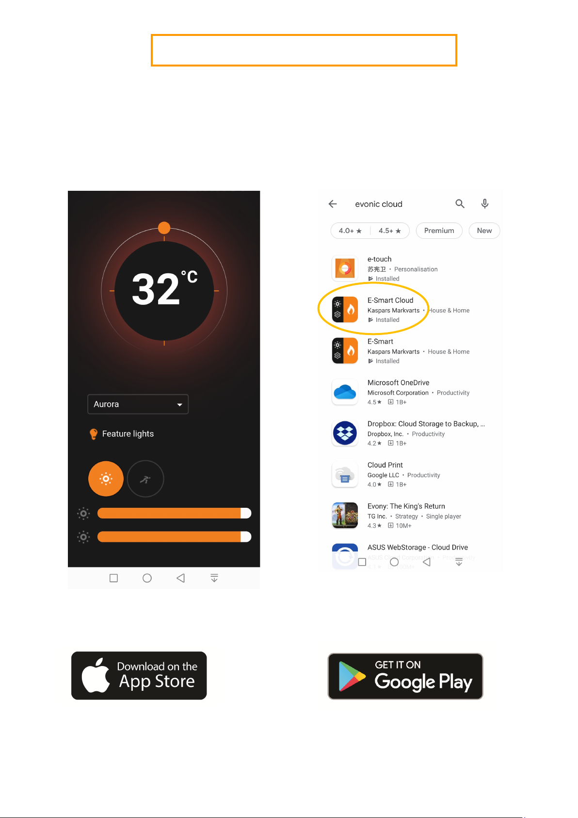
This manual suits for next models
2
Table of contents
Popular Stove manuals by other brands

Cleanburn
Cleanburn Skagen Installation & operating instructions

Pur Line
Pur Line biochimenea Heracles installation instructions

Haas+Sohn
Haas+Sohn HSP 4.0-F3 Equipment sheet

Evonicfires
Evonicfires AAREN instruction manual

Eco Spar
Eco Spar Auriga 23 kW Manual for installation and operation

Haas+Sohn
Haas+Sohn HSP 4.0-F1 Equipment sheet

Comfort Bilt
Comfort Bilt HP61 Operator's manual

bemodern
bemodern Arteon Pryzm 10003SL Instructions for installation

Vanguard
Vanguard SVFBC OWNER'S OPERATION AND INSTALLATION MANUAL

Austro Flamm
Austro Flamm GUSSOFEN G1 User instructions

Procom
Procom SN280TYA OWNER'S OPERATION AND INSTALLATION MANUAL

Kingsman
Kingsman FDV300 instruction manual