CK WORLDWIDE MT200-AC/DC User manual

Please read and
understand this
instruction manual
carefully before
operating this
equipment.
MT200-AC/DCMT200-AC/DC
THE STANDARD
IN TIG WELDING
WELDING MACHINE OWNER’S MANUAL
FORM MT200-OM
CSA E60974-1
www.CKWORLDWIDE.com

2
WARRANTY
• 3 Years from date of purchase.
• CK Worldwide, Inc. warranties all goods as specified by the manufacturer of those goods.
• This Warranty does not cover freight or goods that have been interfered with.
• All goods in question must be repaired by an authorized repair agent as appointed by this company.
• Warranty does not cover abuse, mis-use, accident, theft, general wear and tear.
• New product will not be supplied unless CK Worldwide, Inc. has inspected product returned for
warranty and agrees to replace product.
• Product will only be replaced if repair is not possible.
CALIFORNIA PROPOSITION 65
WARNING: This product contains or produces a chemical known to the State of California to cause cancer and birth
defects (or other reproductive harm) (California Health and Safety Code Section 25249.5 et seq.)
WARNING: This product, when used for welding or cutting, produces fumes or gases which contain chemicals known
to the State of California to cause birth defects and, in some cases, cancer (California Health and Safety Code Section
25249.5 et seq.).
INFORMATION SOURCES
• California Health and Safety Code, Section 25249.4 through 25249.13.
• The California Office of Environmental Health Hazard Assessment, 301 Capitol Mall, Sacramento, CA 95814; telephone 916-445-6900.
• California Proposition 65 website: www.oehha.ca.gov/prop65.html.
• American National Standards Institute (ANSI). Product Safety Signs And Labels (ANSI Z535.4), available from ANSI,
25 West 43rd Street, New York, NY 10036; telephone: 212-642-4900; web site: www.ansi.org.
THANK YOU FOR YOUR PURCHASE OF THE
CK WORLDWIDE MT200-AC/DC TIG WELDING SYSTEM.
At CK Worldwide, we take pride in the trusted quality, innovation, and support we deliver to our customers
and the TIG welding community as a whole. The MT200-AC/DC is the next step in our progression as
“The Standard in TIG Welding” marking the continuing evolution of CK Worldwide. This TIG Welding System
is the latest development in inverter technology. It has been tested and approved by production welders
and the best TIG welding professionals in the industry.
Providing solutions through innovation and new product creation have been mainstays of CK Worldwide
since its inception. It is the very principle by which we do business. Our goal has always been to provide an
outstanding product that not only stands out from its competitors, but also reflects the quality we strive for
in every aspect of our business philosophy. From customer service excellence to technical support,
we work hard at what we do so that you can too.
We know you will enjoy using this machine. Please let us know if you have any questions or concerns.
The MT200-AC/DC is manufactured and compliant with CAN/CSA E60974-1 & ANS/IEC 60974-1,
guaranteeing you electrical safety and performance.
Please view full Warranty terms and conditions
on page 38 of this manual.

3
CONTENTS PAGE
Warranty Overview..............................................................................................................................................................2
Machine Operating Safety....................................................................................................................................... 4–5
MT200-AC/DC Machine Overview ............................................................................................................................6
MT200-AC/DC System Components.......................................................................................................................7
MT200-AC/DC Specifications .......................................................................................................................................8
Machine Layout & Descriptions..................................................................................................................................9
Front Panel Selector Switch Function Descriptions...............................................................................10
Front Panel Control Dial Function Descriptions.........................................................................................11
Cautions / Maintenance / Trouble Shooting..................................................................................................12
Machine Installation & Operation...........................................................................................................................13
Set Up & Operation for DC TIG Welding...................................................................................................14–15
DC TIG Welding....................................................................................................................................................................... 16
Pulse TIG Welding, Pulse DC TIG Welding........................................................................................................17
Example: Pulse DC TIG Welding...............................................................................................................................18
TIG Welding Fusion and Filler Wire Technique ............................................................................................19
Set Up & Operation for AC TIG Welding ..................................................................................................20 – 21
Traditional vs. Square Wave Technology AC TIG Welding........................................................22– 23
Example: Pulse AC TIG Welding................................................................................................................................24
Remote Controls: Installation and Operation................................................................................................25
Set Up & Operation for SMAW (Stick) Welding................................................................................ 26 – 27
SMAW (Stick) Welding Description / Fundamentals ..................................................................28–29
Tungsten Electrode Selection & Preparation.....................................................................................30–32
Troubleshooting Guide — SMAW (Stick) Welding .................................................................................33
Troubleshooting Guide — GTAW (TIG) Welding ............................................................................34–35
TIG Torch Parts............................................................................................................................................................36 – 37
Warranty Terms.....................................................................................................................................................................38
Additional TIG Products ..................................................................................................................................................39
CK WORLDWIDE, INC.
Phone: 1.800.426.0877 Fax: 1.800.327.5038
P.O. Box 1636, Auburn, Washington 98071 USA www.CKWORLDWIDE.com
CONNECT WITH US ON:
THE STANDARD
IN TIG WELDING
Use the MT200-AC/DC
to weld:
•Aluminum
•Titanium
•Magnesium
•Stainless Steel
•Low Alloy Steel
•Deoxidized Copper
•And much more!
REPAIRS
MOTOR SPORTS
OFF ROAD
FABRICATION
MARINE
CUSTOMIZATION

4
•Do not switch the function modes while the machine is welding. Switching of the function
modes during welding can damage the machine. Damage caused in this manner will not be
covered under warranty.
•Disconnect the electrode-holder cable from the machine before switching on the machine,
to avoid arcing should the electrode be in contact with the work piece.
•Operators should be trained and or qualified.
ELECTRIC SHOCK: It can kill. Touching live electrical parts can cause fatal shocks or severe
burns. The electrode and work circuit is electrically live whenever the output is on. The input
power circuit and internal machine circuits are also live when power is on. Incorrectly installed
or improperly grounded equipment is dangerous.
•Connect the primary input cable according to American standards and regulations. ANSI Z49.1.
•Avoid all contact with live electrical parts of the welding circuit, electrodes and wires with bare
hands. The operator must wear dry welding gloves while he/she performs the welding task.
•The operator should keep the work piece insulated from himself/herself.
•Keep cords dry, free of oil and grease, and protected from hot metal and sparks.
• Frequently inspect input power cable for wear and tear, replace the cable immediately if damaged,
bare wiring is dangerous and can kill.
•Do not use damaged, under-sized, or badly joined cables.
•Do not drape cables over your body.
FUMES AND GASES ARE DANGEROUS: Smoke and gas generated while welding or cutting can
be harmful to people’s health. Welding produces fumes and gases. Breathing these fumes and
gases can be hazardous to your health.
•Do not breathe the smoke and gas generated while welding or cutting, keep your head out of
the fumes.
• Keep the working area well ventilated, use fume extraction or ventilation to remove welding
fumes and gases.
•In confined or heavy fume environments always wear an approved air-supplied respirator.
Welding fumes and gases can displace air and lower the oxygen level causing injury or death.
Be certain the air in your work environment is safe to breathe.
• Do not weld in locations near degreasing, cleaning, or spraying operations. The heat and rays
of the arc can react with vapors to form highly toxic and irritating gases.
• Materials such as galvanized, lead, or cadmium plated steel, contain elements that can give
off toxic fumes when welded. Do not weld these materials unless the area is very well ventilated,
and or wearing an air supplied respirator.
ARC RAYS: Harmful to people’s eyes and skin. Arc rays from the welding process produce
intense visible and invisible ultraviolet and infrared rays that can burn eyes and skin.
•Always wear a welding helmet with correct shade of filter lens and suitable protective clothing
including welding gloves while the welding operation is performed.
• Measures should be taken to protect people in or near the surrounding working area. Use protective
screens or barriers to protect others from flash, glare and sparks; warn others not to watch the arc.
MACHINE OPERATION SAFETY
ELECTRIC SHOCK: It can kill
FUMES AND GASES ARE
DANGEROUS
ARC RAYS: harmful to people’s
eyes and skin
SAFETY
Welding and cutting equipment can be dangerous to both the operator and people in or near the surrounding working
area, if the equipment is not correctly operated. Equipment must only be used under the strict and comprehensive
observance of all relevant safety regulations. Read and understand this instruction manual carefully before the
installation and operation of this equipment.
www.CKWORLDWIDE.com

5
FIRE HAZARD: Welding on closed containers, such as tanks, drums, or pipes, can cause them
to explode. Flying sparks from the welding arc, hot work piece, and hot equipment can cause
fires and burns. Accidental contact of electrode to metal objects can cause sparks, explosion,
overheating, or fire. Check and be sure the area is safe before doing any welding.
• Welding sparks may cause fire, therefore remove any flammable materials away from the working
area, at least 40 feet (12m) from the welding arc. Cover flammable materials and containers with
approved covers if unable to be moved from the welding area.
• Do not weld on closed containers such as tanks, drums, or pipes, unless they are properly prepared
according to the required Safety Standards to insure that flammable or toxic vapors and substances
are totally removed, these can cause an explosion even though the vessel has been “cleaned”.
Vent hollow castings or containers before heating, cutting or welding. They may explode.
•Do not weld where the atmosphere may contain flammable dust, gas, or liquid vapors
(such as gasoline).
•Have a fire extinguisher nearby and know how to use it. Be alert that welding sparks and hot
materials from welding can easily go through small cracks and openings to adjacent areas. Be
aware that welding on a ceiling, floor, bulkhead, or partition can cause fire on the hidden side.
GAS CYLINDERS: Shielding gas cylinders contain gas under high pressure. If damaged, a cylinder
can explode. Because gas cylinders are normally part of the welding process, be sure to treat
them carefully. CYLINDERS can explode if damaged.
•Protect gas cylinders from excessive heat, mechanical shocks, physical damage, slag, open flames,
sparks, and arcs.
• Insure cylinders are held secure and upright to prevent tipping or falling over.
•Never allow the welding electrode or earth clamp to touch the gas cylinder, do not drape welding
cables over the cylinder.
• Never weld on a pressurized gas cylinder, it will explode and kill you.
•Open the cylinder valve slowly and turn your face away from the cylinder outlet valve and
gas regulator.
GAS BUILD UP:The build up of gas can cause a toxic environment by depleting the air’s oxygen
content and potentially resulting in injury or death.
•Shut off shielding gas supply when not in use.
• Always ventilate confined spaces or use approved air-supplied respirator.
ELECTRONIC MAGNETIC FIELDS:MAGNETIC FIELDS can affect implanted medical devices.
•Wearers of pacemakers and other implanted medical devices should keep away.
•Implanted medical device wearers should consult their doctor and the device manufacturer
before going near any electric welding, cutting or heating operation.
NOISE CAN DAMAGE HEARING: Noise from some processes or equipment can damage hearing.
Wear approved ear protection if noise level is high.
HOT PARTS: Items being welded generate and hold high heat and can cause severe burns. Do not
touch hot parts with bare hands. Allow a cooling period before working on the welding gun. Use
insulated welding gloves and clothing to handle hot parts and prevent burns.
FIRE HAZARD
GAS CYLINDERS Shielding gas
cylinders contain gas under high
pressure. If damaged, a cylinder
can explode
ELECTRONIC MAGNETIC FIELDS
can affect implanted medical devices
NOISE CAN DAMAGE HEARING
HOT PARTS
GAS BUILD UP
www.CKWORLDWIDE.com

6
OVERVIEW
The MT200-AC/DC is a 220V/115V square wave AC/DC TIG inverter welder incorporating full TIG
functionality including AC balance control, gas pre flow and post flow, variable pulse parameters, high
frequency (HF) start, and remote current control. The HF start provides easy arc ignition leaving no
tungsten inclusion and no contamination of the tungsten electrode. The pulse function with adjustable
frequency and background current gives you the added capability to better control heat input into the
work, control penetration and control distortion. The AC balance control lets you set the AC TIG arc for
cleaning of the oxide layer on aluminum and adjust for a deeper penetrating weld. The foot control
provides variable amperage adjustment during welding. Combining the functions of the MT200-AC/DC
ensures comprehensive control of the welding parameters when welding both AC and DC, giving you
the ability to produce professional TIG welds. The DC SMAW (stick) welding capability delivers a smooth
and stable arc allowing easy welding with electrodes obtaining high quality welds with cast iron,
stainless, and mild steels. The MT200-AC/DC has set the benchmark for 220V/115V single phase AC/DC
welders and is ideal for multiple applications; aluminum and stainless steel fabrication, light industrial
use, repair and maintenance. Robust and reliable, built to our specifications and manufactured in
compliance to CAN/CSA E60974-1 & ANSI/IEC 60974-1.
MT200-AC/DC WELDING MACHINE
“As a welder of critical aircraft hardware, this
machine is extremely easy to use and runs as
smooth as our more expensive machines at work.”
– R. Harper, AIRCRAFT WELDER, 38 YEARS EXPERIENCE
www.CKWORLDWIDE.com

7
FOOT PEDAL
AMPERAGE
CONTROL
SYSTEM COMPONENTS
www.CKWORLDWIDE.com
SINGLE-FLOW
REGULATOR POWER ADAPTER
ACCESSORIES / CONSUMABLES AK-3
3 Cups 3 Collets 3 Collet Bodies
3 Tungsten Electrodes
1 Short Backcap
COMPLETE WELDING SYSTEM INCLUDES:
• MT200-AC/DC
• CK17 Flex-Head Torch with 12.5' (3.8m)
Super-Flex
™
Cable CK17-12-RSF FX
• Dinse Connector SL2-35MT
• AK-3 Accessories/Consumables Kit AK-3
• Foot Pedal Amperage Control
• Ground Clamp with 12.5' (3.8m) Cable
• Single Flow Regulator
• 6' (1.8 m) Gas Hose ARH-6
• 220V to 115V Power Adapter
CK17 FLEX-HEAD TORCH
CK-17-12-RSF FX
GROUND
CLAMP
DINSE CONNECTOR SL2-35MT
SUPER-FLEX
™
POWER CABLES
12.5 feet (3.8m) long
GAS HOSE ARH-6
6 feet
(1.8m)
150 amp ACHF or DCSP @ 100%
Gas-Cooled
Length: 8-3/4" (22.2cm)
Weight: 5 oz. (141gm)
Flexible torch
neck for precise
positioning
12.5 feet
(3.8m)
1 Long Backcap

8
WELDS: Aluminum, Zinc Alloy, Carbon Steels, Alloy Steels, Stainless, Cast Iron, Bronze, Copper
200AMP AC/DC TIG WELDING MACHINE
SQUARE WAVE, PULSE, REMOTE CONTROL
GTAW (TIG)/SMAW (Stick) 200 Amp AC/DC Inverter Welder
High Frequency (HF), Pulse, Post Gas, Remote, Square Wave AC
Features
• Latest IGBT Inverter Technology
• AC/DC TIG
• HF TIG Function (provides easy arc start,
prevents tungsten damage)
• AC Square Wave with Adjustable
AC Balance Control
• Adjustable Pulse Control:
1 – 200Hz
• Adjustable Background Current:
10 – 100%
• Adjustable Post Gas:
0.5 – 20 seconds
• DC SMAW (stick)
• Remote Amperage
Control
Input Voltage 115VAC ±15%, 50/60Hz
220VAC ±15%, 50/60Hz,
single phase
Input Current (I max) 115V: 21 Amps
220V: 34 Amps
Output Current Range
GTAW
115V: 5 – 140 Amps
220V: 5 – 200 Amps
Output Current Range
SMAW
115V: 10 – 110 Amps
220V: 10 – 160 Amps
Rated Output
GTAW
115V: 140A @ 15.6V,
40% duty cycle
220V: 200A @ 18.0V,
25% duty cycle
Rated Output
SMAW
115V: 110A @ 24.4V,
25% duty cycle
220V: 160A @ 26.4V,
30% duty cycle
Max. Open Circuit Volts 74 volts
Gas Pre-flow 0.5 seconds
Gas Post-flow 0.5 – 20 seconds
AC Frequency 20 – 250 Hz
Pulse Frequency 1 – 200 Hz
Pulse Width 50%
Background Current 10 – 100%
Arc Start High Frequency
Dimensions Height: 15 in. (381mm)
Width: 8.5 in. (217 mm)
Length: 20 in. (502mm)
Weight 32 lb. (14.5 kg)
MT200-AC/DC SPECIFICATIONS
www.CKWORLDWIDE.com

9
200AMP AC/DC TIG WELDING MACHINE
SQUARE WAVE, PULSE, REMOTE CONTROL
FRONT VIEW
BACK VIEW
Amperage Display
Pulse Selector
Remote Control Selector
AC/DC Selector
AC Frequency
Control
AC Balance
Control
Negative Output
Terminal
Gas Out
Connector
Remote
Control Socket
Serial Number
Input Gas
Connector
On/Off Switch
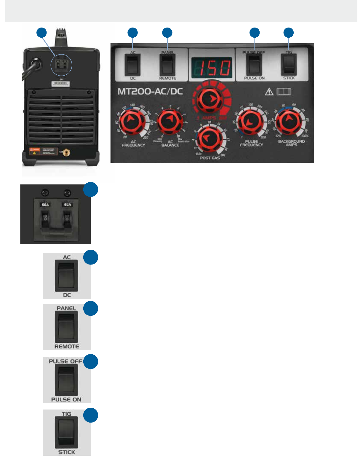
ON/OFF SWITCH
(Located on the back of the
machine)
Primary
Power Input
TIG/Stick
Selector
Background
Amps
Control
Pulse
Frequency
Control
Post Flow Gas
Control
Positive Output
Terminal
Amperage
Selector
MT200-AC/DC
www.CKWORLDWIDE.com
The blue zones on the control
dial indicators are standard
starting positions for most
TIG welding operations.
10
ON/OFF: This switch powers the machine up when switched to the on position
and powers the machine down when switched to the off position. NOTE: The On/Off
switch is on the back of the MT200-AC/DC.
AC/DC: Provides selection of AC or DC current in TIG mode.
Selecting the AC position provides for AC welding current output.
Selecting the DC position provides for DC welding current output.
SELECTOR SWITCH FUNCTION DESCRIPTIONS
21 3 4 5
1
2
3
4
5
PANEL/REMOTE: Provides selection of remote or panel output current control in TIG mode.
Selecting the PANEL position allows current control from the front panel Amps control.
Selecting the REMOTE position allows use of a remote current control.
PULSE SELECTOR: Provides selection of Pulse welding mode in TIG mode.
Selecting the PULSE ON position places the machine in Pulse welding mode.
Selecting the PULSE OFF position places the machine in standard (non-pulse)
welding mode.
TIG/STICK: Provides selection of TIG or SMAW (Stick) welding modes.
Selecting the TIG position provides for TIG welding function.
Selecting the STICK position provides for DC SMAW (Stick) welding function.
www.CKWORLDWIDE.com

11
CONTROL DIAL FUNCTION DESCRIPTIONS
A
B E
F
C
D
A
B
C
D
E
F
The blue zones
on the control
dial indicators are
standard starting
positions for
most TIG welding
operations.
AMPS: Provides adjustment and
control of the main welding current.
Adjustment range 5– 200 Amps
(220V), 5–140 Amps (115V)
PULSE FREQUENCY: Provides
adjustment and setting of the pulse
frequency when the machine is set
in Pulse mode. It adjusts the amount
of times per second (Hz) the output
current switches from the peak current
setting to background current setting.
Adjustment is 1 – 200Hz.
AC FREQUENCY: Adjusts the AC
output frequency to control the arc
cone width and improve directional
control of the arc. Adjustment range
20 – 250 Hz.
AC BALANCE: To understand how balance
control works, you first need to understand
why aluminum and magnesium require
an AC welding output. These materials
have an insulating surface oxide layer that
melts at a higher temperature than the
base metal making it difficult to weld the
base metal if the oxides are not removed.
AC welding current is ideal because the
nature of the AC output assists in breaking
the surface oxide layer. The AC Balance
dial is for adjusting the current flow time
between positive (+) and negative (-).
When set at the Max Cleaning position,
the time that the tungsten is positive (+)
is 50% which promotes an aggressive
cleaning action of the oxide film from the
material surface. When set at the Max
Penetration position, the time that the
tungsten is negative (+) is 85% which
tightens the arc and provides deeper
penetration.
POST GAS FLOW: Provides adjustment
and control of gas flow after the
welding arc is extinguished. Post gas
flow prevents contamination of the
weld pool during its cool down period
from molten state to solid at the weld
finish and keeps the tungsten electrode
protected from oxidizing atmosphere
during the cool down cycle. The Post
Gas flow time will depend on the
tungsten size and welding current that
is being used, when the Post Gas flow is
set correctly the tungsten electrode will
have a clean shiny finish. Adjustment
0.5 – 20 seconds.
BACKGROUND AMPS: Provides
adjustment and control of the
background welding current during
pulse welding. Settings represent
a percentage of the peak welding
current. For example, peak current
set at 100 amps with background
current set at 20% (20 amps) it means
the output current during the pulse
cycle will go from 100 amps down
to 20 amps during each pulse cycle.
Adjustment range: 10 – 100%.

12 www.CKWORLDWIDE.com
1. WORKING ENVIRONMENT
1.1 The environment in which this welding equipment is installed must be free of grinding dust,
corrosive chemicals, flammable gas or materials etc, and at no more than maximum of 80% humidity.
1.2 When using the machine outdoors protect the machine from direct sun light, rain water and snow
etc; the temperature of working environment should be maintained within –14°F to +104°F (–25.5°C
to 40°C).
1.3 Keep this equipment 1 foot (0.3m) away from the wall.
1.4 Ensure the working environment is well ventilated.
2. SAFETY TIPS
2.1 Ventilation: This equipment is small in size, compact in structure and is efficient in
producing welding output. The fan is used to dissipate heat generated by this equipment
during the welding operation.
IMPORTANT: Maintain good ventilation of the louvers of this equipment. The minimum distance
between this equipment and any other objects in, or near, the working area should be 1 foot (0.3m).
Good ventilation is of critical importance for the normal performance and service life of this equipment.
2.2 Thermal Overload Protection: Should the machine be used to an excessive level, or in high
temperature environment, poorly ventilated area or if the fan malfunctions, the Thermal Overload
Switch will be activated and the machine will cease to operate. Under this circumstance, leave the
machine switched on to keep the built-in fan working to bring down the temperature inside the
equipment. The machine will be ready for use again when the internal temperature reaches safe level.
2.3 Over-Voltage Supply: Regarding the power supply voltage range of the machine, please refer
to Specifications. The MT200-AC/DC features automatic voltage compensation within the given range.
If the input power exceeds the stipulated value, it is possible to cause damage to the components of
this equipment. Please ensure your primary power supply is correct.
2.4 Do not come into contact with the output terminals while the machine is in operation.
An electric shock may possibly occur.
MAINTENANCE
Exposure to extremely dusty, damp, or corrosive air is damaging to the welding machine. In order to
prevent any possible failure or fault of this welding equipment, blow the dust out at regular intervals
with clean and dry compressed air of required pressure.
PLEASE NOTE: Lack of maintenance can result in the cancellation of the warranty; the warranty of
this welding equipment will be void if the machine has been modified, or if an attempt is made to
take apart the machine or open the factory seal of the machine without the consent of an authorized
representative of the manufacturer.
TROUBLESHOOTING
CAUTION: Only qualified technicians are authorized to undertake the repair of this welding
equipment. For your safety and to avoid electrical shock, please observe all safety notes and
precautions detailed in this manual.
NOTE: Minimum Motor Generator Power Suggested: 10KVA
Good ventilation is of
critical importance
for the normal
performance and
service life of this
equipment
Exposure to extremely
dusty, damp, or
corrosive air is
damaging to the
welding machine
For your safety and
to avoid electrical
shock, please observe
all safety notes and
precautions detailed
in this manual
CAUTION

13
RECOMMENDED PROCEDURE IS AS FOLLOWS:
1. Connect the regulator to the gas cylinder, and the gas hose assembly to the regulator and
machine. Securely tighten all connections.
2. Slowly open the cylinder valve.
3. Set the flow rate on the regulator to approximately 15–25CFH (7–12LMN).
4. Close the cylinder valve and pay attention to the needle indicator of the contents pressure
gauge on the regulator, if the needle drops away towards zero there is a gas leak.
Sometimes a gas leak can be slow and to identify it will require leaving the gas pressure
in the regulator and line for an extended time period. In this situation it is recommended
to open the cylinder valve, set the flow rate to 15 – 25CFH (7–12LMN), close the cylinder
valve and check after a minimum of 15 minutes.
5. If there is a gas loss then check all connectors for leakage by brushing or spraying with
soapy water. Bubbles will appear at the leakage point.
6. Tighten fitting connections to eliminate gas leakage.
IMPORTANT! We strongly recommend that you check for gas leakage prior to
operation of your machine. We recommend that you close the cylinder valve
when the machine is not in use.
CK Worldwide, Inc. authorized representatives or agents of CK Worldwide, Inc.
will not be liable or responsible for the loss of any gas.
ATTENTION! CHECK FOR GAS LEAKS
Please install the machine strictly according to the following steps.
The protection class of this machine is IP21S, so avoid using it in rain.
CONNECTION OF INPUT CABLES
Primary input cable is supplied with this welding equipment. Connect the primary
input cable with power supply of required input voltage. Refer to data plate on
machine for Input voltage, IMAX.
INSTALLATION & OPERATION
At initial set up and at
regular intervals we
recommend checking
for gas leakage
Avoid using this
machine in the rain
www.CKWORLDWIDE.com

14
INSTALLATION SET UP FOR DC TIG WELDING
INSTALLATION SET-UP FOR DC TIG WELDING
1 6
7
8
9
2
3
4
5
4
7 6
5
2
8
9
1
3
Connect the TIG torch to the
terminal.
Connect the Ground Clamp cable
to the terminal.
Turn on the machine using the ON/OFF switch (located
on the back of the machine).
Select the TIG function with the TIG/STICK selector switch.
Select DC using the AC/DC selector switch.
Connect the TIG torch connector to the negative terminal
and tighten it.
Connect the ground cable connector into the positive
terminal and tighten it.
Connect the foot pedal remote lead into the
remote socket.
Connect the torch gas connector into the gas
receptacle.
Connect the gas regulator to the cylinder and
connect gas line to the regulator.
Carefully open the valve of the gas cylinder,
set the flow to 15-25CFH (7-12LMN).
Set TIG/STICK selector
switch to TIG.
Connect the regulator to the
cylinder, connect the gas lead
to the regulator.
Carefully open the valve of the gas cylinder,
set the flow to 15-25CFH (7-12LMN).
Valve located underneath the safety cover.
Turn the machine ON using the
ON/OFF switch (located on the
back of the machine).
Select DC using the
AC/DC selector switch.
Insert the torch gas connector
into the receptacle.
Connect the foot pedal lead
to the remote socket.

15
OPERATION FOR DC TIG WELDING
Assemble the front end torch parts using the correct size
and type of tungsten electrode needed for the job. The
tungsten requires a sharpened point for DC welding.
Set the maximum welding current (amps) to be used with
the Amps control knob, observing the value set on the
digital display.
Hold the torch above the work piece with a 1/8" (3.2mm)
gap between the tungsten and work piece.
Depress the foot pedal partially to ignite the arc across
the gap between tungsten and the work piece. Maintain
the 1/8" (3.2mm) gap between the tungsten and the work
piece to maintain the arc.
The foot pedal may be depressed more to increase
the welding current up to the panel pre-set value on
the display, or depressed less to decrease the welding
current.
To discontinue welding, slowly decrease depressing
the foot pedal.
Continue holding the torch over the end of the weld until
the gas stops flowing.
A
B
C
D
E
F
G
HF (high frequency) ignition allows the arc to be started in TIG welding without touching the tungsten to the work
piece. By depressing the foot pedal the machine will activate the gas flow and the HF ignition resulting in the arc
igniting across the gap between the tungsten electrode and the work piece. The distance between the electrode
and the work piece can be up to 1/4" (6.3mm). This arc ignition method prevents tungsten inclusion in the work
piece, promotes longer tungsten life and offers better operator control over starting and stopping the arc.
A
B
Having trouble? Please see GTAW (TIG)
troubleshooting information on pages 34 & 35
Hold the torch above the
work piece with a 1/8"
(3.2mm) gap between the
tungsten and work piece.
Depress the foot pedal
partially and the arc will
ignite across the gap
between the tungsten and
work piece. Hold even 1/8"
(3.2mm) gap between the
work piece and the tungsten
to maintain the arc.
D E

16
HF ARC IGNITION FOR TIG WELDING
HF (high frequency) ignition allows the arc to be started in TIG (tungsten inert gas) welding
without touching the tungsten to the work piece. By depressing the foot pedal the machine will
activate the gas flow and introduce the HF (high frequency) (high voltage) spark, this “ionizes”
the air gap making it conductive allowing an arc to be created without touching the tungsten
to the work piece. The gas molecules are superheated by the arc creating a stream of super
heated gas that changes the molecular structure producing a plasma stream. This plasma
stream provides heat and energy that allows us to melt and fuse metals in an inert gas shielded
environment known as TIG (tungsten inert gas) welding.
.
.
.
.
.
.
.
.
.
.
. .
.
.
Gas
molecules
Gas flow HF Plasma
stream
30%
70%
High
current
Low
current
Power source
Argon
gas
Nozzle
DC TIG WELDING
www.CKWORLDWIDE.com
The DC power source produces what is known as DC (direct current) in which the main
electrical component known as electrons flow in only one direction from the negative pole
(terminal) to the positive pole (terminal). In the DC electrical circuit there is an electrical
principle at work which should always be taken into account when using any DC circuit.
With a DC circuit 70% of the energy (heat) is always on the positive side. This needs to be
understood because it determines what terminal the TIG torch will be connected to (this rule
applies to all the other forms of DC welding as well).
DC TIG welding is a process in which an arc is struck between a tungsten electrode and the
metal work piece. The weld area is shielded by an inert gas flow to prevent contamination of
the tungsten, molten pool and weld area. When the TIG arc is struck the inert gas is ionized
and superheated changing it’s molecular structure which converts it into a plasma stream.
This plasma stream flowing between the tungsten and the work piece is the TIG arc and can
be as hot as 34,000°F (18,871°C). It is a very pure and concentrated arc which provides the
controlled melting of most metals into a weld pool. TIG welding offers the user the greatest
amount of flexibility to weld the widest range of material and thickness and types. DC TIG
welding is also the cleanest weld with no sparks or spatter.
The intensity of the arc is proportional to the current that flows from the tungsten.
The welder regulates the welding current to adjust the power of the arc. Thin material
requires a less powerful arc with less heat to melt the material so less current (amps) is
required. Thicker material requires a more powerful arc with more heat so more current
(amps) are necessary to melt the material.

17
No pulse
High frequency
pulsing
Pulse TIG welding is when the output current changes between high and low current.
Electronics within the welding machine create the pulse cycle. Welding is done during the
high-current interval (referred to as peak current). During the low-current interval (referred to as
background current) the weld pool cools due to an overall lower heat input into the base metal.
Pulsed output allows for controlled heating and cooling periods during welding, providing better
operator control of heat input, weld penetration and weld appearance.
The MT200-AC/DC has three variables within the pulse cycle:
Peak Current - Background Current - Pulse Frequency
Setting and manipulation of these variables will determine the nature of the weld current output
and is at the discretion of the operator.
PEAK CURRENT is the main welding current set to melt the material being welded and works
the same as setting maximum current values for regular TIG welding.
BACKGROUND CURRENT is the level set to cool the weld puddle and lower the overall heat
input. Background current is a percentage of peak current. As a rule, use enough background
current to reduce the weld pool to about half its normal size while still keeping the weld pool
fluid. As a guide start by setting the background current at 40 to 60 percent of peak current.
PULSE FREQUENCY is the control of the amount of times per second (Hz) that the welding
current switches from peak current to background current. DC Pulse TIG frequency ranges from
1 to 200 Hz depending on the job application. Control of the pulse frequency
also determines the appearance of the weld.
DC PULSE TIG WELDING
DC Pulse TIG welding allows faster welding speeds with better
control of the heat input to the work, which is an advantage in the
welding of thin stainless and carbon steels. It reduces the heat
input, minimizing distortion and warping of the work. The high
pulse frequency capability of the advanced inverter agitates the
weld puddle and allows you to move quickly without transferring
too much heat to the surrounding metal. Pulsing also constricts and
focuses the arc cone which increases arc stability and penetration.
No pulse
High frequency
pulsing
PULSE TIG WELDING
www.CKWORLDWIDE.com
The MT200-AC/DC has
three variables within
the pulse cycle:
Peak Current
Background Current
Pulse Frequency
Peak
Background
ON OFF
CURRENT
TIME

18
PULSE DC TIG WELDING — SET UP PARAMETERS:
The following steps are a guide for you to set the machine up in Pulse mode. You can experiment
by changing any of the variables to see what effect it has over the weld. It is suggested that you
change only one variable at a time and then check the results. In this way you acquire a better
understanding of how each variable affects the outcome of the weld.
TIME = 1 SECOND
110A
55A 55A 55A
50%
110 A
50%
PEAK CURRENT
BACKGROUND AMPS
On
Time
PULSE WIDTH
Example of Pulse vs Non-Pulse
weld finish
EXAMPLE OF PULSE DC TIG WELDING
1
2
3
4
5
Prepare the machine for DC TIG welding
Set the Pulse switch to PULSE ON
Set the Peak Current at 110 Amps
Set the Background Amps around 50%
(Background Amps is a percent of the Peak Current,
e.g. 50% of 110 = 55 Amps)
Set the Pulse Frequency around 2 Hz (pulses
per second)
3 2
45
Set the Peak Current at 110 Amps Set to PULSE ON
Set the Background
Amps around 50%
Set the Pulse Frequency around
2 Hz (pulses per second)
PULSE
NON-PULSE
www.CKWORLDWIDE.com

19
TIG FUSION TECHNIQUE
TIG FILLER WIRE
TECHNIQUE
TIG WELDING WITH FILLER WIRE TECHNIQUE
It is necessary in many situations with TIG welding to add a filler wire into the weld pool to build
up weld reinforcement and create a strong weld. Once the arc is started, the tungsten is held in
place until a weld pool is created, a circular movement of the tungsten will assist in creating a
weld pool of the desired size. Once the weld pool is established tilt the torch at about a 75° angle
and move smoothly and evenly along the joint. The filler metal is introduced to the leading edge of
the weld pool. The filler wire is usually held at about a 15° angle and fed into the leading edge
of the molten pool. The arc will melt the filler wire into the weld pool as the torch is moved
forward. A dabbing technique can be used to control the amount of filler wire added, the wire
is fed into the molten pool and retracted in a repeating sequence as the torch is moved slowly
and evenly forward. It is important during the weld process to keep the molten end of the filler
wire inside the gas shield as this protects the end of the filler wire from being oxidized and
contaminating the weld pool.
75°
15°
Form a weld pool
Travel direction
Angle torch Add TIG filler wire
Retract the filler wire Move the torch forward to
the front of the weld pool
Repeat the process
gas
shield
TIG WELDING FUSION TECHNIQUE
Manual TIG welding is often considered the most difficult of all the welding processes. Because
the welder must maintain a short arc length, great care and skill are required to prevent contact
between the electrode and the work piece. Similar to Oxygen Acetylene torch welding, TIG welding
normally requires two hands. The welder manually feeds a filler wire into the weld pool with one
hand while manipulating the welding torch in the other. However, some welds combining thin
materials can be accomplished without filler metal, like edge, corner, and butt joints. This is known
as Fusion welding, where the edges of the metal pieces are melted together using only the heat
and arc force generated by the TIG arc. Once the arc is started the torch tungsten is held in place
until a weld pool is created, a circular movement of the tungsten will assist in creating a weld pool
of the desired size. Once the weld pool is established, tilt the torch at about a 75° angle and move
smoothly and evenly along the joint while fusing the materials together.
75°
Form a weld pool Angle torch Move the torch slowly and
evenly forward
TIG WELDING FUSION/FILLER WIRE TECHNIQUES
www.CKWORLDWIDE.com

20
INSTALLATION SET-UP FOR AC TIG WELDING
INSTALLATION SET UP FOR AC TIG WELDING
1 6
7
8
9
2
3
4
5
4
7 6
5
2
8
9
1
3
Connect the TIG torch to the
terminal.
Connect the Ground Clamp cable
to the terminal.
Turn on the machine using the ON/OFF switch (located
on the back of the machine).
Select the TIG function with the TIG/STICK selector switch.
Select AC using the AC/DC selector switch.
Connect the TIG torch connector to the negative terminal
and tighten it.
Connect the ground cable connector into the positive
terminal and tighten it.
Connect the foot pedal remote lead into the
remote socket.
Connect the torch gas connector into the gas
receptacle.
Connect the regulator to the cylinder, connect
the gas lead to the regulator.
Carefully open the valve of the gas cylinder,
set the flow to 15-25CFH (7-12LMN).
Set TIG/STICK selector
switch to TIG.
Connect the regulator to the
cylinder, connect the gas lead
to the regulator.
Carefully open the valve of the gas cylinder,
set the flow to 15-25CFH (7-12LMN).
Valve located underneath the safety cover.
Turn the machine ON using the
ON/OFF switch (located on the
back of the machine).
Select AC using the
AC/DC selector switch.
Insert the torch gas connector
into the receptacle. Connect the foot pedal lead
to the remote socket.
Table of contents
Other CK WORLDWIDE Welding System manuals


Popular Welding System manuals by other brands


Lincoln Electric
Lincoln Electric Idealarc DC-1500 Operator's manual

Thermal Dynamics
Thermal Dynamics A40 operating manual

EWM
EWM Picomig 355 puls TKM operating instructions

Lincoln Electric
Lincoln Electric SAE -500 Operator's manual

stud welding products
stud welding products StudPro LiteXI Operator's manual

Lincoln
Lincoln 300 Operator's manual

Lincoln Electric
Lincoln Electric SPIRIT II 400 Technical manual

Lincoln Electric
Lincoln Electric SAF-FRO DIGISTEEL 355S Operator's manual

Scheppach
Scheppach WSE3200 Translation of original operating manual

Tool Up
Tool Up Plasma GUTTING Spark 20 manual

REMS
REMS EMSG 160 instruction manual

Miller
Miller LMSW-52T owner's manual