CK WORLDWIDE WF5 User manual
1
Cold Wire Feeder Manual
September 2015
CK Worldwide, Inc.
3501 C St. N.E. Auburn, WA 98002
tel: (253) 854-5820
tel: (800) 426-0877
fax: (253) 939-1746
The important safeguards and instructions appearing in
this pamphlet should be read and understood prior to
operating your equipment.
NOTE:
Safety Warning ................................................................
Warranty ..........................................................................
Introduction .....................................................................
Description ......................................................................
TIG Welding Process ........................................................
Specifications ..................................................................
Check List ........................................................................
Optional Items .................................................................
Installation .......................................................................
Operation .........................................................................
Welding............................................................................
Maintenance....................................................................
Troubleshoot Chart ...........................................................
Cables and Guides ............................................................
Feeding Difficult Wires / Bracket Extensions ....................
Electrical Diagram ...........................................................
FunctionsofControls........................................................
Parts Lists: WF5 Feed Unit Left Side ....................
WF5 Feed Unit Right Side .................
CWH1812 Hand Torch .......................
CWH2312 Hand Torch .......................
CWHTL312 Hand Torch .....................
Parts Lists: CWH3512 Hand Torch.........................
CWM2312 Machine Torch .................
CWM3512 Machine Torch .................
CWMT412 Machine Torch .................
CWMT512 Machine Torch .................
CWH Wire Feed Hand Unit .................
CWMES Remote Switch ....................
Drive Rolls .......................................................................
Spare Parts .....................................................................
CWH1812HeadAccessories .............................................
CWH2312HeadAccessories .............................................
CWHTL312 Head Accessories .........................................
CWH3512 ........................................................................
CWM2312 HeadAccessories ............................................
CWM3512 HeadAccessories ............................................
CWMT412 Head Accessories ..........................................
CWMT512 Head Accessories ..........................................
Tungsten Electrode Information ......................................
Tungsten Preparation ......................................................
Welding Parameters .......................................................
2-3
4
4
4-5
5
6
7
7
7-9
10
10
10
11
12
12
13
14
15
16
17
17
18
18
19
19
20
20
21
21
21
21
22
22
23
23
24
25
26
27
28
29
30-31
2
WARNING:
UNSAFE PROCEDURES OR PRACTICES CAN CAUSE SERIOUS PERSONAL INJURY OR DEATH.
All end users of this equipment, the operators and helpers, must read and understand these safety instructions.
This product, when used for welding or cutting, produces fumes or gases which contain chemicals known to the
State of California to cause birth defects and, in some cases, cancer.
California Health & Safe Code 25249.5 et seq.
PREVENT ELECTRICAL SHOCK:
Touching live electrical parts can cause severe burns or fatal shock.
1. Do not touch live electrical parts.
2. Do not work in wet or damp areas.
3. Wear dry insulating gloves and body protection.
4. Disconnect all power before installing or servicing this equipment.
5. Turn off all equipment when not in use.
6. Properly install and ground the welding power source according to its Owner’s Manual and all applicable
codes.
7. Do not use worn or damaged cables or cables that are too small or poorly spliced.
8. Do not wrap cables around your body.
9. Do not touch electrode and any grounded object or circuit at the same time.
10. Use only well-maintained equipment. Repair or replace damaged parts at once.
PROVIDE PROTECTION FROM FUMES AND GASES:
Breathing welding fumes and gases can be hazardous to your health.
1. Keep your head out of welding fumes.
2. Use adequate ventilation in the work area to keep fumes and gases from your breathing zone and the
general work area.
3. If ventilation is inadequate, use an approved breathing device.
4. Read and understand the Material Safety Data Sheets (MSDS) and the manufacturer’s instructions for any
materials used.
Gas cylinders are normally used when welding, treat them with care.
1. Protect compressed gas cylinders from excessive heat, mechanical shocks and arcs.
2. Install and secure cylinders so that they cannot fall or tip over by fastening them to a mounting bracket,
wall or other stationary support.
3. Keep cylinders away from any welding or other electrical circuits.
4. Never allow a welding electrode to touch any cylinder.
PROTECT COMPRESSED GAS CYLINDERS:
PROTECT EYES AND SKIN FROM ARC RAYS, PROTECT EARS FROM NOISE:
Welding arc rays produce intense heat and ultraviolet rays that can burn eyes and skin. Noise from some
processes can also damage hearing.
1. Wear a welding helmet fitted with a proper filter lens (see ANSI Z49.1 for detailed information).
2. Use protective screens or barriers to protect others from welding flash and glare.
3. Wear protective clothing and foot protection.
NOTE: The important safeguards and instructions
appearing on this pamphlet should be read and
understood prior to operating your equipment.

3
The hot workpiece, hot equipment, spatter, and arc sparks can cause fires and burns.
PREVENT FIRES AND BURNS:
1. Wear correct eye, face, and body protection in the work area.
2. Allow work and equipment to cool before handling.
3. Do not weld near flammable materials.
4. Watch for fire, and keep a fire extinguisher nearby.
5. For additional information, refer to NFPA Standard 51B, “Fire Prevention in Use of Cutting and Welding
Processes”, available from the National Fire Protection Association, Batterymarch Park, Quincy MA 02269.
PROVIDE PROTECTION FOR SPECIAL SITUATIONS:
1. Do not weld or cut containers or materials which have held or been in contact with hazardous substances
unless they are properly cleaned and inspected.
2. Do not weld or cut painted or plated parts unless special ventilation is provided to remove highly toxic
fumes or gases.
3. Since welding can affect pacemakers, keep all pacemaker wearers out of the work area. Have them
consult a doctor before coming near a welding operation.
PROVIDE PROPER EQUIPMENT MAINTENANCE:
Improperly maintained equipment can result in poor work, but most importantly it can cause physical injury or
death through fires or electrical shock.
1. Always have qualified personnel perform the installation, troubleshooting, and maintenance work. Do not
perform any electrical work unless you are fully qualified.
2. Before performing any maintenance work inside a power supply, disconnect the power supply from the
electrical power source.
3. Maintain cables, grounding wire, connections, power cord, and power supply in a safe working order. Do
not operate any equipment in questionable condition.
4. Do not abuse any equipment or accessories. Keep equipment away from heat sources such as furnaces,
wet conditions such as water puddles, oil or grease, corrosive atmospheres, and inclement weather.
5. Keep all safety devices, guards, panels, and covers in position and in good repair.
6. Use equipment for its intended purpose. Do not modify it in any manner.
For more information on safe practices for setting up and operating electric welding and cutting equipment and
on good working habits, ask your welding equipment supplier. For your protection, read and comply with the
latest editions of the following standards:
1. ANSI Standard Z49.1
Available from the American Welding Society, 550 N.W.
LeJeune Rd., Miami FL 33126.
2. ANSI Standard Z87.1
“Safe Practices for Occupation and Educational Eye and
Face Protection”, available from the American National
Standards Institute, 1430 Broadway, New York, NY 10018.
3. AWS Standard A6.1
“Recommended Safe Practices for Shielded Arc Welding”,
available from the American Welding Society 550 N.W.
LeJeune Rd., Miami FL 33126.
4. AWS Standard F4.1
“Recommended Safe Practices for the Preparation for
Welding and Cutting of Containers and Piping that have
Held Hazardous Substances”, available from the American
Welding Society 550 N.W. LeJeune Rd., Miami FL 33126.
ADDITIONAL SAFETY INFORMATION:
5. CSA Standard W117.2
“Code for Safety in Welding and Cutting”, available from
the Canadian Standards Association, 178 Rexdale Blvd.,
Rexdale, Ontario, Canada M9W 1R3.
6. NFPA Standard 51B
“Fire Prevention in Use of Cutting and Welding Processes”,
available from the National Fire Protection Association,
Batterymarch Park, Quincy MA 02269.
7. NFPA Standard 70
“National Electrical Code”, available from the National
Fire Protection Association, Batterymarch Park, Quincy MA
02269.
8. OSHA Standard 29 CFR, Part 1910, Subpart Q
“Welding, Cutting, and Brazing”, available from the
Superintendant of Documents, U.S. Government Printing
Office, Washington D.C. 20402.

4
CK Worldwide, Inc. warrants the cold wire feed unit (WF-5) against defects in materials and
workmanship for a period of one year from the date of purchase. Should it become defective for such
reason, the Manufacturer will repair it without charge, if it is returned to the Manufacturer’s factory,
freight prepaid. Prior to returning the equipment, written authorization, in the form of an RGA number
must be obtained prior to any returns for any reason. This warranty does not cover: (1) failure due
to normal wear and tear; (2) consumable parts, such as, but not limited to, feed cables, wire guides,
torch and torch parts; (3) damage by accident, force majeure, improper use, neglect, unauthorized
repair or alteration; (4) any one other than the original purchaser. In any event, CK Worldwide, Inc. will
only be responsible for its products when used with accessory items manufactured by CK Worldwide,
Inc.
This limited warranty is in lieu of all other warranties, express or implied. The manufacturer shall
not be liable for any injury to persons, including death; or loss or damage to any property, direct or
consequential, including, but not limited to loss of use, arising out of the use, or the inability to use, the
product. The user assumes all risk and liability whatsoever in connection with the use of the product,
and before doing so shall determine its suitability for his intended use, and shall ascertain the proper
method of using it. This warranty gives you specific legal rights, and you may have other rights,
which may vary from state to state.
The CK Cold Wire TIG System consists of (1) The Cold Wire TIG Wire Feed Unit and (2) The Cold Wire
TIG Torch Outfit. The Wire Feed Unit is a model WF-5. The TIG Torch Outfit includes the feed cable and
wire guide. The application and features of each is described below. See pages 17 through 21 for the
model numbers of standard CK Cold Wire TIG Torch Outfits
WF5:
The WF5 Wire Feed Unit can be used with hand held CK torches for semiautomatic operation or with
machine mounted CK torches for fully automatic operation. The WF5 Feed Unit houses the drive
motor, feed roll mechanism, solid state control circuitry, and spool of filler wire. It has a ten turn
potentiometer for wire feed speed adjustment and a toggle switch for continuous or pulsed wire feed
operation. For automatic operation, it has controls for delay start and wire retract capabilities. The
WF5 is supplied with one dual grooved drive roll for two sizes of wires and one pressure roll of the
size and type best suited for the filler wire being used (as specified at time of order). See page 21 for
a range of available drive rolls.
The patented CK Cold Wire TIG System is used in the Gas Tungsten Arc Welding (GTAW) / Tungsten Inert
Gas (TIG) process to provide automatic or semiautomatic feeding of the filler metal. Depending on
the configuration of the system, it can be used to feed .025” (.65m) through 1/16” (1.6mm) diameter
stainless steel / alloy steel wire or .035” (.9mm) through 1/16” (1.6mm) aluminum wire from standard
12” (30.5mm) spools.
WARRANTY:
INTRODUCTION:
DESCRIPTION:

5
TORCH OUTFIT:
The CK Cold Wire TIG Torch Outfit is a hand held or machine mounted CK TIG torch with the built
in added capacity of delivering a filler wire directly to the weld puddle.The torch outfit includes
torch, power cable, feed cable, wire guide and wire guide bracket. The feed cable is fitted with
a replaceable, low-friction cable liner. Various torch configurations are available. All models use
standard CK collets, collet bodies and gas cups. See pages 22 through 27 for parts and order
numbers.
DIRECT CURRENT STRAIGHT POLARITY (DCSP):
DC straight polarity produces the deepest penetration because the heat of the weld is concentrated
at the work or joint. Straight polarity provides no cleaning action (removal of surface oxides). This
polarity is generally used to weld most materials except aluminum and magnesium. May be used
with or without high frequency starting.
DIRECT CURRENT REVERSE POLARITY (DCRP):
DC reverse polarity provides good cleaning action. The combining force of the shielding gas ions
striking the work surface and the flow of electrons from the work, cause thesurface oxides to be
broken away. Penetration is shallow because the heat of the weld is concentrated at the electrode.
The use of DCRP is limited to special applications. Maybe used with or without high frequency
starting.
ALTERNATING CURRENT HIGH FREQUENCY (ACHF):
AC combines the good penetration of straight polarity (electrode negative half cycle) and the good
cleaning action of reverse polarity (electrode positive half cycle). Continuous high frequency is
necessary to reestablish the arc which breaks between each half cycle. ACHF current is generally
used to weld aluminum and magnesium.
The TIG welding process uses a nonconsumable tungsten electrode secured in the TIG torch. The
welding arc is produced between the tungsten electrode and the work. The weld is shielded by a
stream of Argon gas, Helium gas, or a mixture of the two, which is fed through the torch, around the
electrode and to the molten weld puddle. Filler metal is added to the weld puddle as required. The
Cold Wire TIG System mechanizes the addition of the filler metal to ensure consistent, high quality
welds.The TIG welding process is the first choice for welding thin sections, welding thin-wall tubing,
making pipe joint root passes, and other similar critical welding applications.
NOTE: Cold Wire TIG welding of tubing under 2-1/2” (6.4cm) diameter requires
CWH pendant style feed unit and separate TIG torch. Unless being used with
turn table or pipe roller.
The TIG welding process requires a constant current welding power source. Power sources designed
specifically for TIG welding may include a built in high frequency arc stabilizer, shielding gas control
solenoid, cooling water control solenoid and other special equipment. They may be AC or DC or a
combination of AC/DC units. The proper current for TIG welding depends on the material being welded,
speed of application and on the desired weld characteristics.
DESCRIPTION:
TIG WELDING
PROCESS:

6
SPECIFICATIONS: WF5 WIRE FEED UNIT:
HAND TORCHES:
MACHINE TORCHES*:
*REMOTE SWITCH REQUIRED:
PART NUMBER: CWMES
See Page 21
Voltage:
Phase:
Frequency:
Height:
Width:
Length:
Weight:
Filler Wire Spool Size:
Filler Wire Sizes:
Wire Feed Speed Range:
Feed Time (pulsed mode):
Dwell Time (pulsed mode):
Delay Start Time (continuous mode):
Wire Retract Time (continuous mode):
115V AC (220V AC 50hz - special item)
Single Phase
50 / 60 hz.
15 in. (38.1cm)
10 in. (25.4cm)
21 in. (53.3cm)
54 lbs. (24.5 kg. )
12 in. (30.5cm)
.023” (.58mm), .030” (.76mm), .035”
(.9mm), .045” (1.1mm), 1/16” (1.6mm)
0-700 in/min (0-1,775cm/min)
continuously variable
continuously variable
continuously variable
continuously variable
180 amp ACHF or DCSP
300 amp ACHF or DCSP
350 amp ACHF or DCSP
400 amp ACHF or DCSP
Water
12-1/2 ft (3.81m)
8 ft. (2.44m)
10 ft. (3.05m)
300 amp ACHF or DCSP
400 amp ACHF or DCSP
400 amp ACHF or DCSP
500 amp ACHF or DCSP
Water
12-1/2 ft (3.81m)
8 ft. (2.4m)
10 ft. (3m)
CWH1812 Rating at 100% Duty Cycle:
CWH2312 Rating at 100% Duty Cycle:
CWHTL312 Rating at 100% Duty Cycle:
CWH3512 Rating at 100% Duty Cycle:
Cooling Method:
Torch Cable Length:
Feed Cable Length (soft wire):
Feed Cable Length (hard wire):
CWM2312 Rating at 100% Duty Cycle:
CWM3512 Rating at 100% Duty Cycle:
CWMT412 Rating at 100% Duty Cycle:
CWMT512 Rating at 100% Duty Cycle:
Cooling Method:
Torch Cable Length:
Feed Cable Length (soft wire):
Feed Cable Length (hard wire):

7
CHECKLIST:
OPTIONAL
ITEMS:
INSTALLATION:
WF5 Wire Feed Unit
CWMES:
CWH:
ITEMS REQUIRED FOR COLD WIRE TIG WELDING NOT PROVIDED:
Drive Roll Set - for wire size and type specified (installed)
Torch Outfit with Feed Cable, Wire Guide and Wire Guide
Bracket - model specified at time of order
Remote switch with 11 ft. (3.4m) lead - required for machine torch operation, but
must be ordered as a separate item.
The CK Cold Wire TIG Wire Feed Unit requires 115 volts Alternating Current to
operate. The 115V MUST be supplied by an ISOLATED, GROUNDED outlet. Do not
connect to the 115V AC outlet on the power source. 220V also available.
1. Attach the water cooled power cable of the TIG torch to the electrode terminal on the
power source. A power cable adapter is required to make the proper connection (the
water cooled power cable is the water out line).
2. Attach the ground cable from the power source ground terminal to the work or fixture.
The ground cable should be adequate size and no longer than the torch leads.
3. Attach the torch water in and gas supply hoses to their respective connections points.
4. Plug the feed unit control cord into an isolated, grounded 115V AC outlet. Do not con-
nect feed unit control cord into the 115V AC on the welding power source. For feed
units requiring 220V AC, install an appropriate plug. Then plug the feed unit control cord
into an isolated, grounded 220V AC outlet.
5. Do not set the Cold Wire Feeder directly on the power supply without an insulating
barrier.
Hand held feed assembly and remote switch with 8 ft. (2.4m) feed cable for soft
wire, 10 ft. (3m) feed cable for hard wire.
1. Welding power source - suitable for TIG welding.
2. Water recirculator - for cooling welding torch.
3. Regulator / Flowmeter - for control of shielding gas flows.
4. Shielding gas and cylinders.
5. Full cover welding helmet with proper shaded lens.
6. Leather welding gloves.
7. 12” (30.5cm) spool of welding wire.
8. Ground Cable - sized to suit current range - and ground clamp.
8
INSTALLATION: FITTING AND THREADING THE FILLER WIRE:
CAUTION: Do not feed wire through the drive rolls under pressure.
Keep hands away from the wire guide end while feeding
the wire through the feed cable.
When using soft aluminum wire, it may be necessary to
unscrew the compression nut fastening the feed tube to
the wire guide, and manually feed the wire through the
wire guide.
CAUTION:
NOTE:
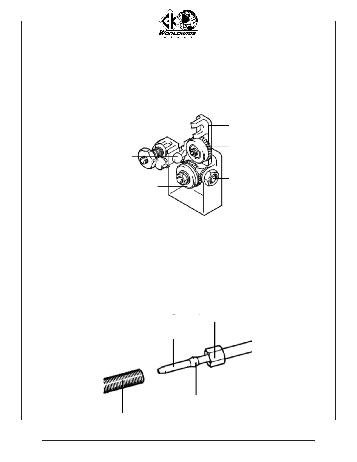
6. Remove the right side Wire Feed Unit cover and install a spool of welding wire. Drive
rolls have two grooves. Check the feed roll to be sure it is on the correct side for the
filler wire being used. See page 21 for drive roll sizes. Unlatch and raise the pressure
roll arm. Thread the wire through the inlet guide to the drive rolls. Feed the wire across
the drive roll groove and into the feed cable inlet guide. Close and relatch the pressure
roll arm.
7. After the wire has been started into the feed cable, straighten feed cable and feed wire
under power by actuating the torch switch. Keep the Feed Cable as straight as possible
and continue pushing the switch until the wire has completely fed through.
Feed Cable Inlet Guide
Drive Roll
Inlet Guide
Pressure Roll
Pressure Roll Arm
Compression Nut
Feed Tube
Wire Guide
Compression Fitting

9
INSTALLATION: WIRE FEED ROLL ADJUSTMENT:
SPOOL BRAKE ADJUSTMENT:
To adjust the feed rolls, tighten the pressure roll adjusting nut
approximately one-half turn past the point where the rolls
just begin to “grab” the welding wire.
Too much braking force will needlessly overload the drive
motor.
Always replace and lock the cover door after loading wire.
Feed rolls that are adjusted too tightly will result in deformed
wire and needless overload of the drive motor.
IMPORTANT:
WARNING:
NOTE:
WARNING:
8. The wire feed rolls and spool brake are properly adjusted at the factory, prior to delivery. As
componenets “seat in”, it may be necessary to adjust the settings.
9. Adjust the spool brake by turning the brake adjusting nut IN to increase braking force and OUT
to decrease the braking force. Adjust the brake just tight enough to prevent the welding wire
from over-running when feeding has stopped.
Pressure Roll
Adjusting Nut
Pressure Roll
Drive Roll
Retaining Clip - CW804
Spool Brake Adjusting Nut

10
OPERATION:
WELDING:
MAINTENANCE:
HAND HELD:
MACHINE:
Prior to commencing welding, the following preparations should be made to ensure
optimum performance of the system.
With the shield gas flowing, initiate an arc between the tungsten electrode and
the workpiece. When the desired weld pool has formed, depress the switch on the
torch to start the wire feeding. Adjust the Wire Speed and, if in Pulse mode adjust
the Drive time and Dwell time to produce the desired bead.
The recommended torch angle for hand held welding is 15° from perpendicular.
The filler wire is fed into the leading edge of the molten pool.
The recommended torch angle for machine mounting welding is perpendicular. The
filler wire is fed into the leading edge of the molten pool.
1. Make sure that the pieces of metal to be welded are free of grease, dirt, paint,
and scale. Use a wire brush to remove dirt and scale. Use a stainless steel wire
brush on stainless or aluminum. Paint must be completely removed to bare metal.
Failure to clean the metal properly will result in porous and contaminated welds.
2. Check that the system has been properly installed per the installation instructions.
3. Check the control cable and weld cables for proper connection. Make sure the
ground clamp is firmly attached to a cleaned area on the piece to be welded.
4. Prepare the torch for welding. Check the gas supply and adjust the flowmeter for
the recommended flow rate. Check the water circulator for proper operation.
5. Set the controls on the power source and the Cold Wire TIG Feed Unit.
1. Blow foreign matter from the feed cable with compressed air before loading a new
spool of welding wire.
2. Replace the wire guide tube if it has been arced, bent, or is badly worn.
3. Wire drive motor brushes should be inspected at regular intervals and replaced if
worked to a 1/4” (6.4mm) length.
Whenever a brush is removed for inspection, be sure it is put back in the
same position. It must not be turned around in the brush holder. Excessive
arcing and loss of power will result if it is put back incorrectly.
NOTE:
Direction of Travel
15°
3-3/4"
Direction of Travel

11
TROUBLESHOOTING
CHART:
This troubleshooting chart is a guide in identifying and correcting possible troubles
which may occur when operating this equipment.
Not affiliated with this equipment, refer to power source owners manual.
PROBLEM CAUSE SOLUTION
Pilot light is out 1. Unit is not plugged in.
2. Switch is in off position.
3. Switch is faulty.
4. Light is burned out.
5. Circuit breaker is blown.
1. Plug in unit.
2. Turn switch to on position.
3. Replace switch.
4. Replace light.
5. Reset or replace circuit breaker.
Drive indicator light does not
light when remote switch is
engaged
1. Light is burned out.
2. Remote switch is faulty.
3. Switch wire is damaged.
4. Amphenol plug is damaged.
5. Motor control board is faulty.
6. Power to unit is off.
1. Replace light.
2. Replace remote switch.
3. Repair or replace switch wire.
4. Repair or replace Amphenol plug.
5. Replace motor control board.
6. Turn power on.
Loss of wire feed 1. Circuit breaker tripped.
2. Motor control board is faulty.
3. Potentiometer is set at zero.
4. Wire supply is exhausted.
5. Wire feed cable tangled.
6. Wire is bird nested.
7. Feeder is unplugged.
8. Feed cable is plugged.
9. Drive roll is misaligned.
10. Drag is excessive.
11. Wire guide tube has worn out.
1. Reset circuit breaker.
2. Replace motor control board.
3. Set wire feed speed.
4. Resupply wire.
5. Straighten feed cable.
6. Loosen pressure roll / re-thread wire.
7. Plug in feeder to a 115V AC wall outlet.
8. Replace feed cable.
9. Align inlet and outlet guides with drive
roll.
10. Adjust spool brake.
11. Replace wire guide tube.
Erratic wire feeding 1. Feed unit plug is connected to power
supply.
2. Wire tangled on spool.
3. Wrong or worn feed cable.
4. Wrong or worn wire guide.
5. Wrong drive roll groove.
6. Incorrect drive roll pressure.
7. 12V DC relay failed.
1. Unplug then plug into 115V AC wall
outlet.
2. Remove tangled section and rethread.
3. Replace feed cable.
4. Replace wire guide.
5. Refer to chart on Page 21.
6. Adjust pressure roll.
7. Replace relay.
Faulty Delay - Retract 1. Potentiometer failed.
2. Toggle switch failed.
3. 12V DC relay failed.
1. Replace potentiometer.
2. Replace toggle switch.
3. Replace relay.
Motor will not turn off 1. Faulty trigger switch.
2. Switch control cable damaged.
3. Amphenol plug shorted.
4. 12V DC relay failed.
5. Logic board failed.
1. Repair or replace switch.
2. Repair or replace cable.
3. Repair or replace plug.
4. Replace relay.
5. Replace logic board.
Wire will not feed 1. Coiled feed cable - friction on wire.
2. Wire is bent or curved.
1. Keep feed cable as straight as possible.
2. Keep wire straight as it enters feed
rolls.
Loss of weld current 1. Weld cables disconnected.
2. Power source contactor open.
3. Poor contactor connection.
1. Repair or replace cables.
2. Check contactor connections.
3. Make proper connections.
Erratic weld current 1. Poor ground connection.
2. Poor welding cable connection.
1. Make proper connections.
2. Make proper connections.

12
CABLES AND
GUIDES:
WIRE TYPE WIRE SIZE: FEED CABLE:
Hard Wire:
-10 ft. (3m) for
Stainless Steel
-Black Strain Relief
.023” (.55mm) CW-FC
.030” (.8mm) CW-FC
.035” (.9mm) CW-FC
.045” (1.1mm) CW-FC
1/16” (1.6mm) CW-FC116
Soft Wire:
-8 ft. (2.4m) for
Aluminum
-Red Strain Relief
.023” (.55mm) Not recommended
.030” (.8mm) Not recommended
.035” (.9mm) CW-FCN
.045” (1.1mm) CW-FCN116
1/16” (1.6mm) CW-FCN116
TORCHES: WIRE SIZE: REPLACEMENT TIP: REPLACEMENT
TUBE:
WIRE GUIDE
ASSEMBLIES:
Body Mount:
(CWH180)
(CWH230)
(CWM230)
(CWMT500)
.023” (.55mm) CWT023 CWGB
(Curved)
CWGBS
(Straight)(S)
CWG023B(S)
.030” (.8mm) CWT030 CWG030B(S)
.035” (.9mm) CWT035 CWG035B(S)
.045” (1.1mm) CWT045 CWG045B(S)
1/16” (1.6mm) N/A CWG116B(S)
Head Mount:
(CWH), (CWM), (CWH150),
(CWH210), CWHTL312),
(CWH350), (CWM350),
(CWMT400)
.023” (.55mm) CWT023 CWGH
(Curved)
CWGHS
(Straight)(S)
CWG023H(S)
.030” (.8mm) CWT030 CWG030H(S)
.035” (.9mm) CWT035 CWG035H(S)
.045” (1.1mm) CWT045 CWG045H(S)
1/16” (1.6mm) N/A CWG116H(S)
NOTE: A bracket extension is needed for complete installation with a part number of 3-WGBX-60.
FEEDING DIFFICULT
WIRE/BRACKET
EXTENSION:
Due to the nature of certain wires it may be difficult to feed a wire through the length of the feed
cable and through the curved wire guide. Friction and drag may put too much resistance on the wire
when it is forced through the curved wire guide. Typically this is encountered when using very small
diameter soft wires and large diameter hard wires. To alleviate this problem a wire guide extension
bracket is recommended. This will relieve the resistance on the wire. In addition to the use of the
wire guide extension bracket, it is important to keep the feed cable as straight as possible.
PART # 3-WGBX-60

13
WF5 ELECTRICAL DIAGRAM:
120V AC
60 HZ
PILOT
LIGHT
12V DC
RELAY
12V DC
RELAY
LOGIC CIRCUIT
CARD
MOTOR
2 OHM
50 WATT
DELAY
SW-2
DELAY
P-1
RETRACT
SW-3
RETRACT
P-2
1
1
11
12
10
3
2
12
K1 K2
1314
893
6
+12V
11 13 10
9
4
4
C1 C2 C3
5
5
6
7
7 FIELD
8
TRIGGER
MOTOR DRIVE CIRCUIT
CARD
SPEED
ADJUSTMENT
BLACK
BROWN
WHITE
RED

14
A
B
C
D
E
F
G
H
I
J
K
L
M
N
FUNCTIONS OF
CONTROLS:
The following controls are located on the front of the WF5 wire feed unit.
FUNCTIONS OF
CONTROLS:
A. ON / OFF Switch
Main power switch - energizes control circuit
and pilot light.
B. Delay Start Time Control
Variable resistor - sets the time delay from
remote switch actuation to wire feed start.
C. Delay Start ON / OFF Switch
Activates the delay start timer.
D. Drive Time Control
Variable resistor - sets the on time of the wire
feeding into the weld puddle in pulse mode.
E. Pulse / Continuous Selector Switch
Controls mode of operation - Continuous or
Pulse wire feed mode.
F. Circuit Breaker
5 amp breaker provides overload protection for
control circuit.
G Remote Amphenol
WF5 activation.
H. Wire Speed Control
Ten turn potentiometer - controls speed of wire
drive motor.
I. Pilot Light
Illuminates when feed unit is on.
J. Retract Time Control
Variable resistor - controls time of wire in
retract mode.
K. Retract ON / OFF Switch
Activates wire retract circuit.
L. Dwell Time Control
Variable resistor - sets the off time of the wire
when not feeding wire into weld puddle in
pulse mode.
M. Drive Indicator Light
Illuminates when motor is feeding wire.
N. Feed Cable Connection
Connection point for wire feed cable.
15
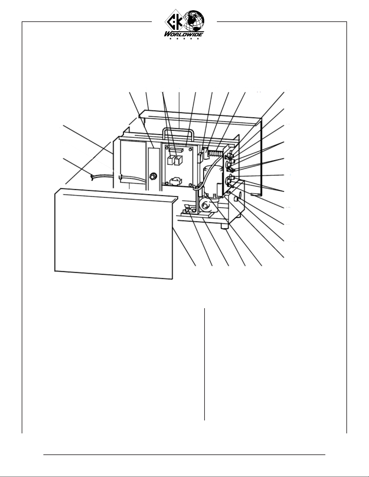
PARTS:
PARTS LIST:
WF5 COLD WIRE FEED UNIT LEFT SIDE VIEW: (see page 18 for right side view)
ITEM:
1
2
3
4
5
6
7
8
9
10
11
12
ITEM:
13
14
15
16
17
18
19
20
21
22
23
24
25
26
27
PART NUMBER:
312003-01
400-0001-81
400-0037-81
400-0004-81
400-0168-87 (2)
DK-1107
400-0170-87
400-2026-95
400-2027-95
01-2207-79
400-0176-79
400-0018-81 (5)
PART NUMBER:
01-5089-79
400-0130-82
400-0129-82
400-0012-81 (4)
400-0009-81 (4)
400-0177-87 (2)
400-0111-81
400-0015-81
11-0051-79
400-0169-87
400-0167-87
001-1107-79 (4)
400-0166-87
400-0181-92
400-0003-81
DESCRIPTION:
Power Cord
Cabinet
Strap, Spool Hub
Right Door
12V DC Relay
Handle
Motor Drive Circuit Card
Fuse Holder
Fuse 5 amp, 250 Volt
2 Ohm Resistor
Terminal Board
Capacitor
3 on Amphenol Connector
2 on Terminal Board
DESCRIPTION:
Pilot Light
10 Turn Dial
10 Turn Potentiometer
2 Position Switch
Knob
100 K Potentiometer
Pilot Light
Circuit Breaker, 5 amp
Amphenol Receptacle
Logic Circuit Card
Motor Spacer
Footpad
Motor Pad
Capacitor
Left Door
1
2
3 4 5 (2) 7 8, 9 10 13
14, 15
16
16 (2)
16
19
20
22
2324252627
17 (2), 18 (2)
17 (2)
21, 12 (3)
11, 12 (2)6

16
PARTS: WF5 COLD WIRE FEED UNIT RIGHT SIDE VIEW:
PARTS LIST:
Consisting of the following:
Consisting of the following:
ITEM:
1
2
3
4
5
6
7
8
9
10
11
12
13
14
15
16
17
18
19
20
ITEM:
21
22
23
24
25
26
27
28
29
30
31
32
33
34
35
36
37
38
39
40
41
42
43
44
PART NUMBER:
CW900
CW400
CW111
CW109
CW110
CW112 (2)
CW113
CW101
CW104
CW103
CW105
CW108
CW100
CW106
CW107
CW303
CW304
CW305
CW306
Drive Roll - Select from:
30-45DR
45-564DR
PART NUMBER:
CW201
CW203
CW204
CW200
CW500
CW503 (3)
CW504 (3)
CW300
CW302
CW301
CW800
CW810
CW805
CW802
CW806
CW811
CW803
CW811
CW801
CW807
CW805
CW808
CW809
CW804
DESCRIPTION:
Motor and Drive Assembly
Motor and Gear Box
Pressure Roll Tension Bolt
Tension Nut
Pressure Spring
Tension Bolt Washer
Tension Bolt Roll Pin
Pressure Roll
Pressure Roll Screw
Pressure Roll Bushing
Pressure Roll Retainer Nut
Pressure Roll Spacer
Pressure Roll Arm
Shoulder Bolt
Spring Washer
Outlet Guide Mount
Outlet Guide Washer
Outlet Guide Nut
Thumb Screw
.030” - .045” (.8mm - 1.1mm) Wire
.045” - 1/16” (1.1mm - 1.6mm) Wire
DESCRIPTION:
Drive Shaft Key
Drive Roll Lockwasher
Drive Roll Nut
Drive Roll Gear
Drive Housing Bracket
Drive Housing Bolt
Drive Housing Lockwasher
Inlet Guide
Inlet Guide Washer
Inlet Guide Nut
Hub Assembly
Bolt
Flat Washer
Tension Spring
Notched Washer
Bushing
Shaft
Bushing
Spool Holder
Nylon Flat Washer
Flat Washer
Lock Washer
Bolt
Wire Spool Retaining Clip
16, 17, 18
25, 26, and 27 28, 29, and 30
32, 33, 34, 35, 36, 37, 38, 40,
41, 42, and 43
3, 4, 5, 6, and 7
20, 21, 22, 23, and 24
8, 9, 10, 11, 12,
13, 14, and 15
1
2
19
31
39
44

17
PARTSLIST:
PARTSLIST:
* Note: See Page 22 for additional
options on head consumables.
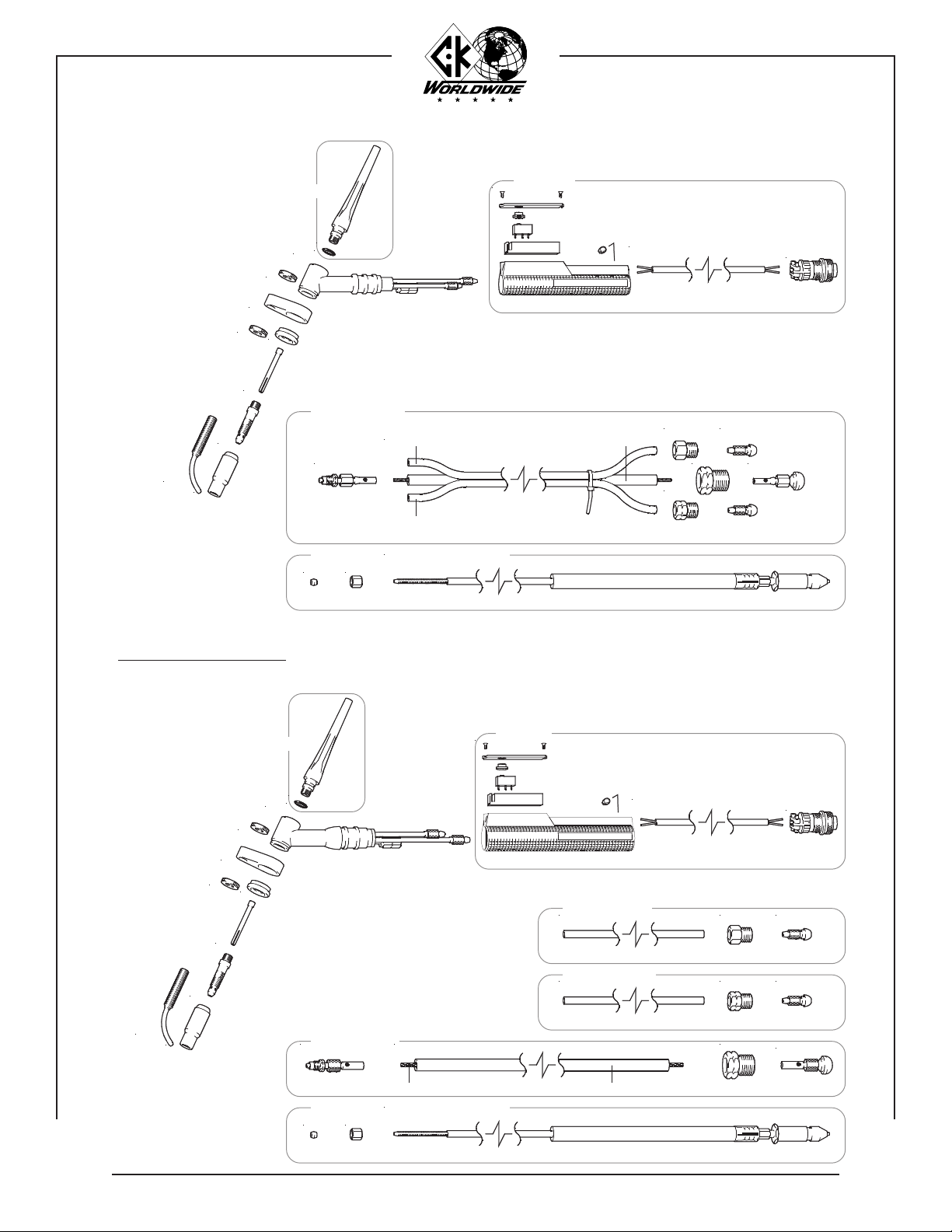
CWH2312 HAND TORCH:
* Note: See Page 22 for additional
options on head consumables.
CWH1812 HAND TORCH:
CWKN
6S5
3035
SWB
SW4
3036
SS1
6S5
CWH23H (including 6S5's and SS1)
SC-BULK 01-0127
CWH23HA
2GHS
CK230
200R
200M
2A7*
2CB332*
2C332GS*
CWKNSee Page 12
CWFCWN1
CWFC or CWFCN
2312TF - 12.5 ft (3.8m)
2AN 3HF
2WN 3HF
2PN 23PF223PF1
2312PC -12.5 ft (3.8m)212AH - 12.5 ft (3.8m)
212WH - 12.5 ft (3.8m)
01-0032
CK180
80THS
8CB332*
8C5*
8C332*
WGB-B
CWKNSee Page 12 CWKN
6S5
3035
SWB
SW4
3036
SS1
6S5
CWH18H (including 6S5's and SS1)
SC-BULK 01-0127
CWH18HA
CWFCWN1
CWFC or CWFCN
212TF - 12.5 ft (3.8m)
2AN 3HF
2WN 3HF
2PN2PF22PF1
2312PC - 12.5 ft (3.8m)212AH - 12.5 ft (3.8m)
212WH -12.5 ft (3.8m)
01-0032
(set screw incl.)
WGB-B
(set screw incl.)
18
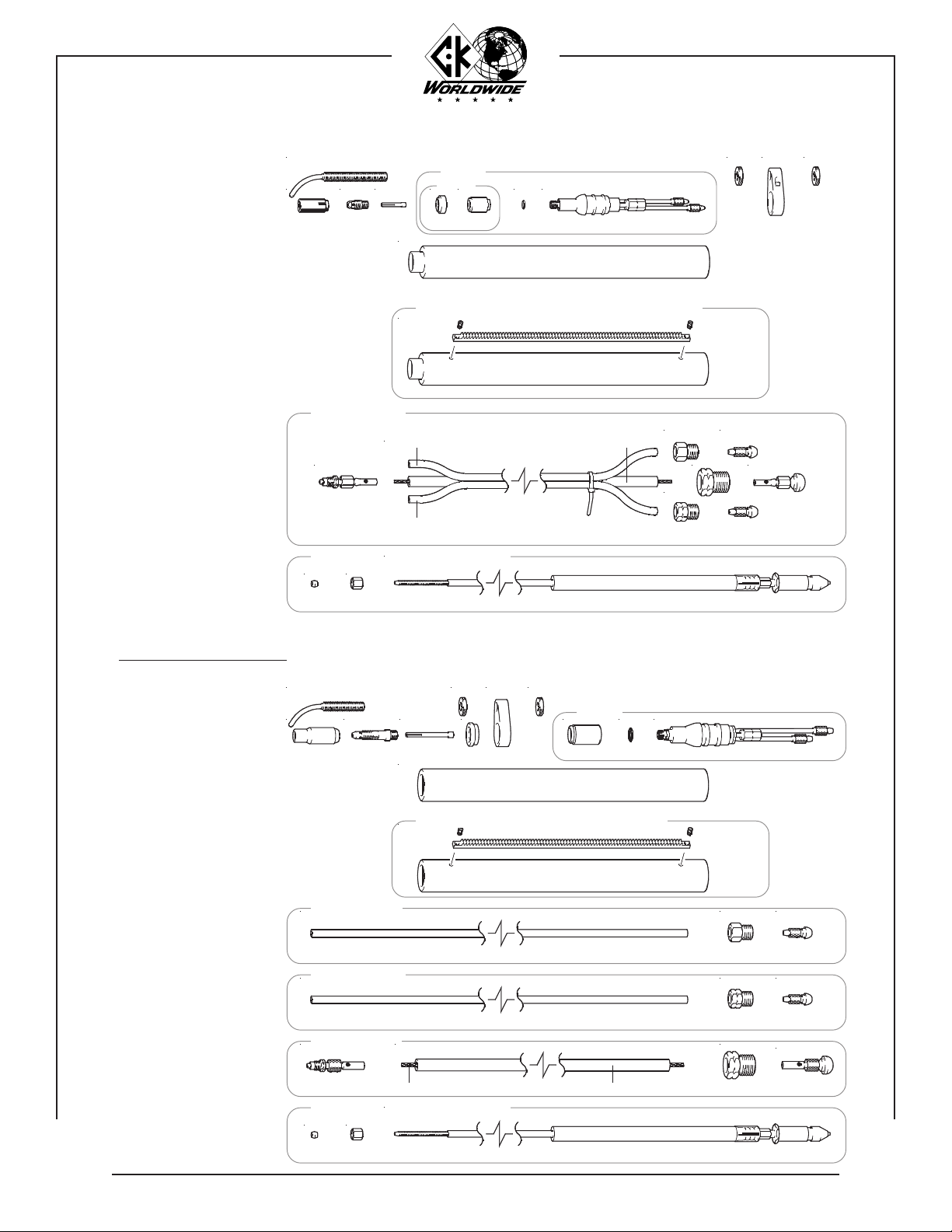
PARTSLIST:
* Note: See Page 23 for additional
options on head consumables.
CWH3512 HAND TORCH:
CWFC or CWFCN / CWFC116 or CWFCN116
CWFCWN1
2312TF 12.5 ft. (3.8m)
2AN 3HF
2WN 3HF
2PN 23PF223PF1
2312PC 12.5 ft. (3.8m)212AH 12.5 ft. (3.8m)
212WH 12.5 ft. (3.8m)
01-0032
CWFC or CWFCN / CWFC116 or CWFCN116
CWFCWN1
CWHTL312 HAND TORCH:
CWKN
CWKN
CWHS
3C332GS*
See Page 12
3A7*
3CB332*
TL300
WGB-3
300R
300L 6S5
3035
SWB
SW4
3036
SS1
6S5
CWHTL3HA
230HE
(including 6S5's and SS1)
SC-BULK 01-0127
512PC 12.5 ft. (3.8m)
2PN 51PF251PF1
2WN 3HF3H-BULK
312WH 12.5 ft. (3.8m)
2AN 3HF3H-BULK
312AH 12.5 ft (3.8m)
PARTSLIST:
CWKN
CWKN
CWHS
3C332GS*
300R
300L
CK350
WGB-3
3CB332*
3A7*
See Page 12
* Note: See Page 23 for additional
options on head consumables.
6S56S5
CWH35HA
300HE
(including 6S5's and SS1)
01-0127SC-BULK
SS1
3036
SW4
SWB
3035
5PCH-BULK5PCW-BULK
19
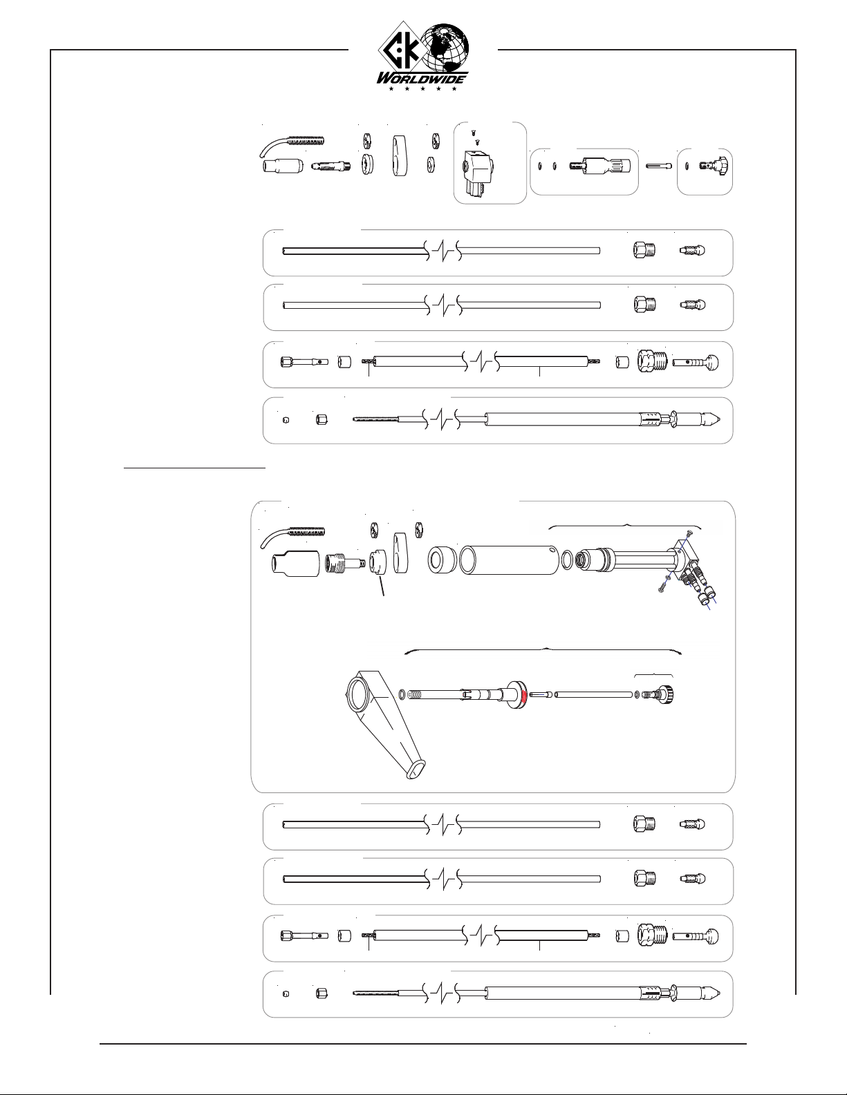
CWM2312 MACHINE TORCH:
CWM3512 MACHINE TORCH:
CWKNCWKN
230M-HCW
PARTSLIST:
PARTSLIST:
2312TF 12.5 ft. (3.8m)
2AN 3HF
2WN 3HF
2PN 23PF223PF1
2312PC 12.5 ft. (3.8m)212AH 12.5 ft. (3.8m)
212WH 12.5 ft. (3.8m)
01-0032
See Page 12
3CB332*3A7*
See Page 12
2A7* 230M-B200R
2GHS
230M-C
2C332GS*
CKM230
350M-C300R350M-B
CKM350
* Note: See Page 24 for additional
options on head consumables.
* Note: See Page 25 for additional
options on head consumables.
CWKNCWKN
CWHS3C332GS*WGB-3
CWFC or CWFCN / CWFC116 or CWFCN116
CWFCWN1
312WH 12.5 ft. (3.8m)
2WN 3HF3H-BULK
312AH 12.5 ft. (3.8m)
2AN 3HF3H-BULK
CWFC or CWFCN / CWFC116 or CWFCN116
CWFCWN1
2CB332*
512PC 12.5 ft. (3.8m)
2PN 51PF251PF1 5PCH-BULK5PCW-BULK
HR-24 or HR-32
HR-SHR-S
230M-HCWR24 or 230M-HCWR32 (optional item - ordered separately)
350M-H
HR-24 or HR-32
350M-HR24 or 350M-HR32 (optional item - ordered separately)
HR-S HR-S
WGB-B
(set screw incl.)
20
CWMT412 MACHINE TORCH:
PARTSLIST:
PARTSLIST:
* Note: See Page 27 for additional
options on head consumables.
CWFC or CWFCN / CWFC116 or CWFCN116
CWFCWN1
312AH 12.5 ft. (3.8m)
2AN 3HF3H-BULK
* Note: See Page 26 for additional
options on head consumables.
CWMT512 MACHINE TORCH:
See Page 12 CWKN
WGB-3
CWHS
3GL332LD*
MT500C-7 (7” - 17.8cm body) or MT500C-18 (18” - 45.7cm body)
CWHS 4C332*
See Page 12
3CB332*3A6* 200R
(2 required)
200R
AS35ACM
WGB-3
CWKNCWKN CWMT400
118-024
(2 required)
CWKN
M512PC-1 12.5 ft. (3.8m)
MTPCFA 5PCH-BULK5PCW-BULK
312WH 12.5 ft. (3.8m)
2WN 3HF3H-BULK
3AG12LD
CWTS
2PN
51F 1184
51F
CWFC or CWFCN / CWFC116 or CWFCN116
CWFCWN1
212AH 12.5 ft. (3.8m)
2AN 3HF2H-BULK
M512PC-1 12.5 ft. (3.8m)
MTPCFA 5PCH-BULK5PCW-BULK
212WH 12.5 ft. (3.8m)
2WN 3HF2H-BULK
2PN
51F 1184
51F
MTSB
INCLUDES WASHER
H1-3
MT500BC - 18 (18” (45.7cm))
or
MT500BC - 7 (7” (17.8cm))
R-7
MTS (3 req.)
MTH-18 (18” (45.7cm))
or
MTH-7 (7” (17.8cm))
1006 (2 req.)
AS35
4CE500 - 7 (7” (17.8cm))
4CXXX*
ACM500 - 7 (7” (17.8cm))
300R
BOOT-MT
4CE500 - 18 (18” (45.7cm))
or
*NOTE: 4 SERIES COLLET REQUIRED
INCLUDES O-RING
ACM500 - 18 (18” (45.7cm))
or
CWHSLD
Table of contents
Other CK WORLDWIDE Welding System manuals


