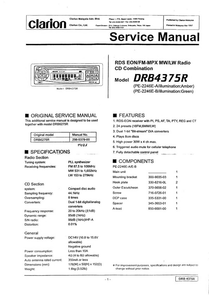
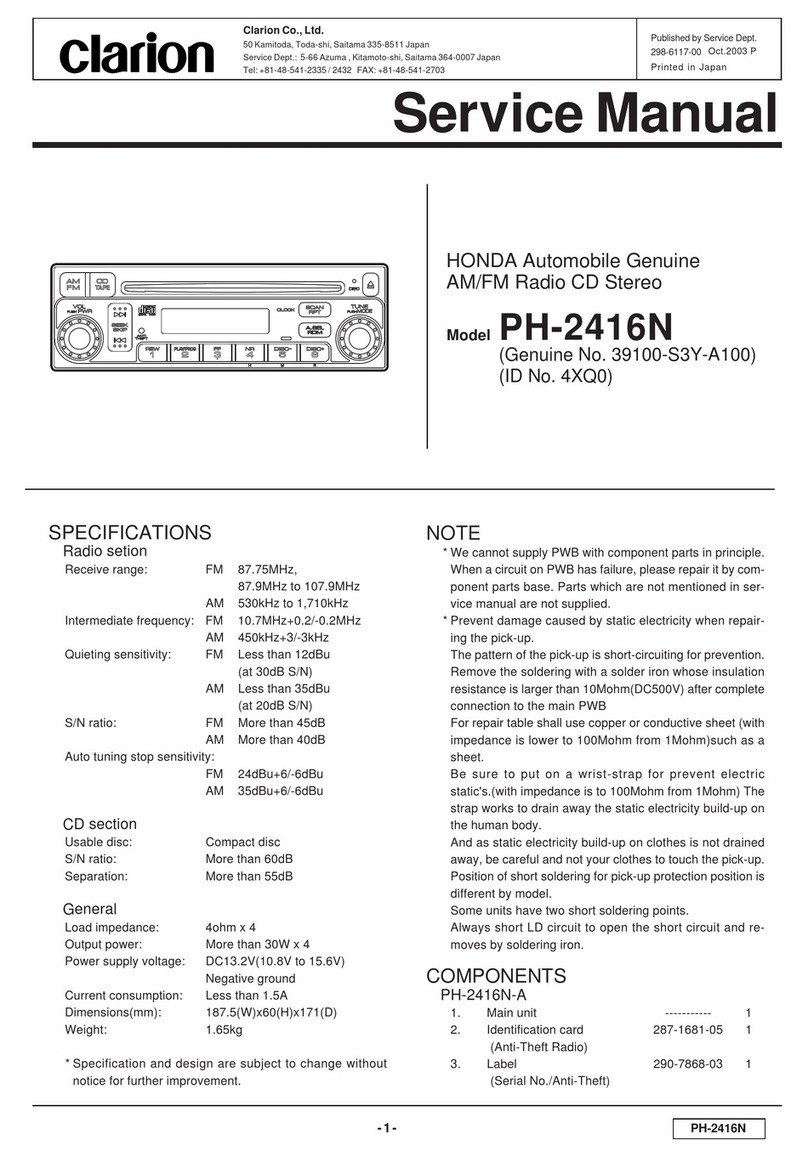
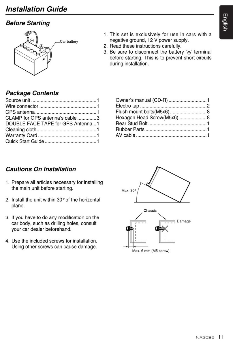
1-2 Adjustment of lF Section
-1. Connect the sweep generator output to TPS and
oscilloscope's vertical terminal to TP6. Turn the tuning
knob of the set fully clockwise.
2. When the sweep generator f requency is set to
452.5KH2 and its output level is increased, a waveform
as shown in Fig- 2 is obtained.
Keep the output of SSG as small as possible and the
vertical gain of oscillosc()pe as large as possible.
3. Adiust the cores of I FT4 and lFT5 of obtain maximum
height of the waveform with good symmetry.
1-3 Tracking adjustment
Apply the output of SSG to the set through dummy
load-
Bring the set's dial pointer to the maximum frequency
point on the dial and set the AM SG to 1620KH2.
Adiust the OSC trimmer (TC6l to receive 162OKHz-
Next set the dial pointer to the left end (minimum
receiving frequencyl, set the SSG signal to 520KHz, and
adjust L4 to receive this signal. Repeat these adiustments
2 - 3 times so that the receiving band width becomes
52OKHz - 1620KH2.
Now adjust the ANT trimmer (TC4) and RF trimmer
(TC5) on the same frequency so that the Audio output
becomes maximum.
15 - 20dB output of SSG is suitable for the adiustment.
The volume and tone controls must be at maximum
position.
2. Adjustment of FM tuner
2-1 lnstruments required
FM standard signal generator (SSG)
FM lF sreep generator (10.7MH2)
Oscilloscope
Dummy load (4Sr)
VTVM
2-2 Adjustment of lF section
1. Connect the sweep generator output to TPI and
oscilloscope's vertical terminal to TP2.
Turn the tuning knob of the set fully clockwise.
2. With the sweep generator frequency set of 10.7MHz
when the output level of the sareep generator is
gradually increased, waveform shown in Fig. 3 appears
on the CRT screen.
Now perform the following adjustment.
Keep the FM SSG output as small as possible and the
vertical gain of oscilloscope as large as possible.
3. Adjust the core (green) of lFTl for maximum height
of the waveform with good symmetry.
Adjust the core (blue) of lFT3 for maximum height of
the waveform.
4. Connect the vertical terminal of oscilloscope to TP3.
Adiust the core (black) of lFT3 for good linearity and
good symmetry of the s-curve.
2-3 Tracking adjustment
1. Turn the tuning knob fully counterclockwise (lowest
receiving f requency position).
Adjust the OSC trimmer (TC3) to receive 87.5MHz
from the FM SSG.
2. furn the tuning knob to receive 98MHz. Set the
output of FM SSG ro approximately lOdB and adjust
the ANT trimmer (TC1) and RF trimmer (TC2) to
obtain maximum audio output.
At this time, the volume control and tone control
knobs must be at maximum position.
2-4 MPX section adjustrnent
1. Turn the ST-MO witch OFF. (Monoral reception).
Connect the oscilloscope vertical input to TP.4 and
apply a precalibrated 19KHz signal (stereo modulator
calibration use signal) to the horizontal input.
Adiust the semi-f ixed control VR5 so that the
Lissajuous waveform becomes almost stationery.
( lf a frequency counter is available, connect it to TP.4
and adiust VR5 so that the frequency becomes exactly
19.OKHz).
-Adiustment of the frequency of voltage controlled
oscillator (vco)-
2. Connect the stereo modulator to FM SSG and set to
the specified modulation depth (pilot signal 7.5KHz).
Turn the ST-MO sryitch ON. (Stereo receptionl.
Set the SSG output to about 25d8.
Adjust the semi-fixed control VR4 by turning it in the
counterclockwise. direction to a position where the ST
indicator lights.
-Adjustment of lndicator lamp sensitivity-
3. This adjustment of lamp (lighting) sensitivity must be
performed after the adjustment of VCO frequency.
The sensitivity increases when VR4 is turned counter-
clockwise and increases when VR4 is turned to clock-
wise direction.
t
Betore adjustrnent Alter adiustrnent
lFis.ql
Does not become perfectly round because the
Lissajuous figure is formed by the rectangular wave-
form (TP.4 outputl and sinusoidal waveform (calibra-
tion use 19KHz signal).
ffi

