6
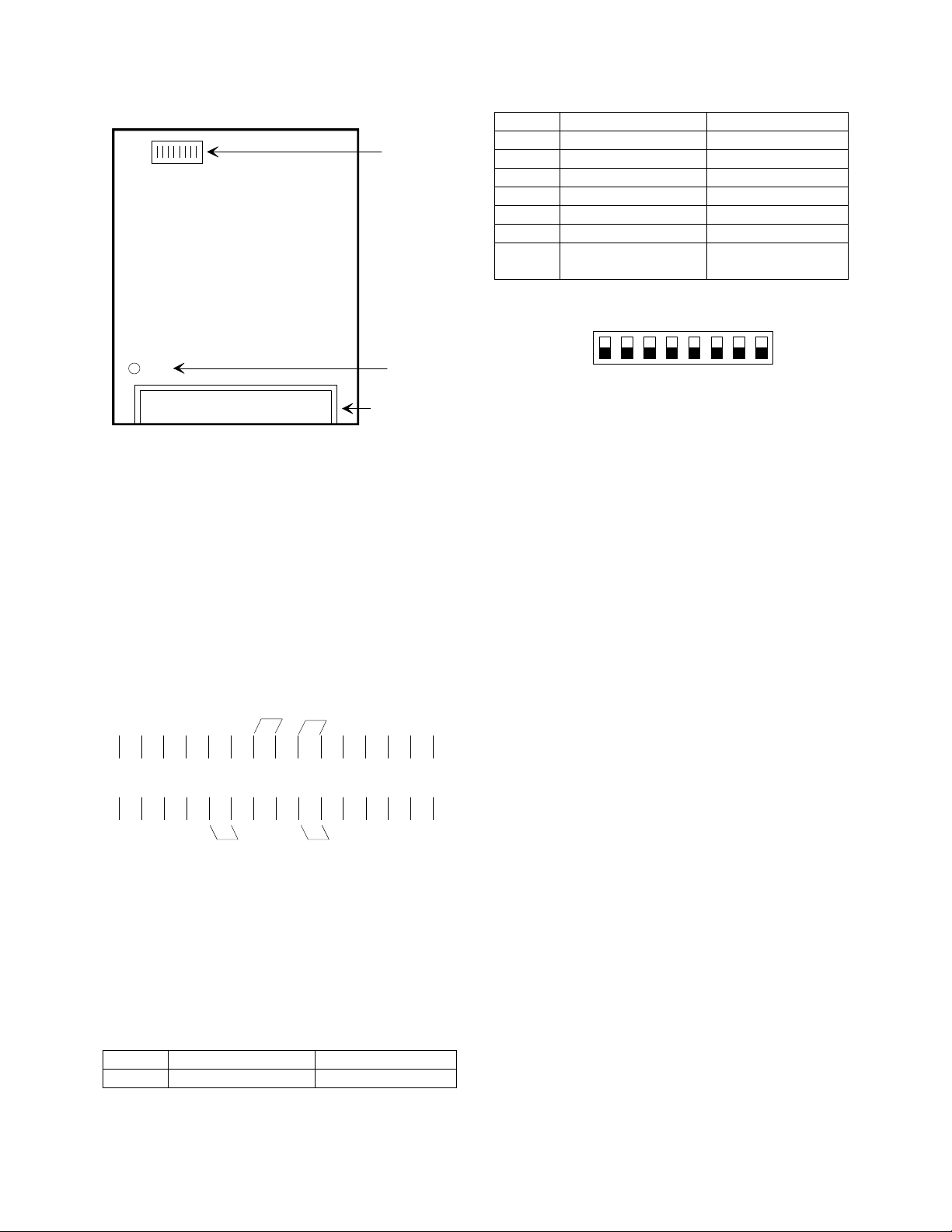
__ 5. Dipswitch Settings: If the STPA is being used
with a PABX extension, then switch 1 must be
OFF. Switch 2 is not used. Turn ON one of
switches 3-7 to select the reset timing (the
length of time the unit stays active after last
sensing audio). Switch 8 must be ON. If the
STPA is being accessed from a Centrex or C.
O. Line, then set dipswitches 1 and 8 "ON" and
switches 2-7 "OFF."
OPERATION
The STPA, Station Level Page Adapter, has three inputs:
Tip and Ring from the line, music, and all call; and two
outputs: 8 ohm and 600 ohm.
Any input will provide audio at both the 8 ohm and 600
ohm outputs. Signals coming from the 8 ohm output will
be processed by the automatic gain control circuitry and
a preamplifier. Music on the 8 ohm output will be
maintained 7db below the level of the paging (this is not
user adjustable). There is no modification of page or
music signals when using the 600 ohm output. The 600
ohm output also provides a loop on access and may be
used with loop start paging equipment.
In the idle state, signals from the music input will appear
on both the 8 ohm and 600 ohm outputs. On receipt of
superimposed ring generator on Tip and Ring, the STPA
will be activated and will place a loop across the station
Tip and Ring for ring trip. An answer verification tone
will then be returned to the calling party, and Tip and
Ring audio will be connected to the 8 ohm and 600 ohm
outputs.
After access, the reset circuitry is turned on. If the unit is
set for loop detect, it will ignore any open conditions for
the first second, and then it will release when it senses an
open loop on Tip and Ring lasting at least 150 ms. If you
are using the audio sense reset, the unit will stay on line
until sensing a lack of audio (-22db or less) for the period
set by the dipswitches. If using the time out reset, the unit
will stay on the line for the preset length of time and then
will reset, whether the page is complete or not. On
release, the music source is reconnected to the outputs.
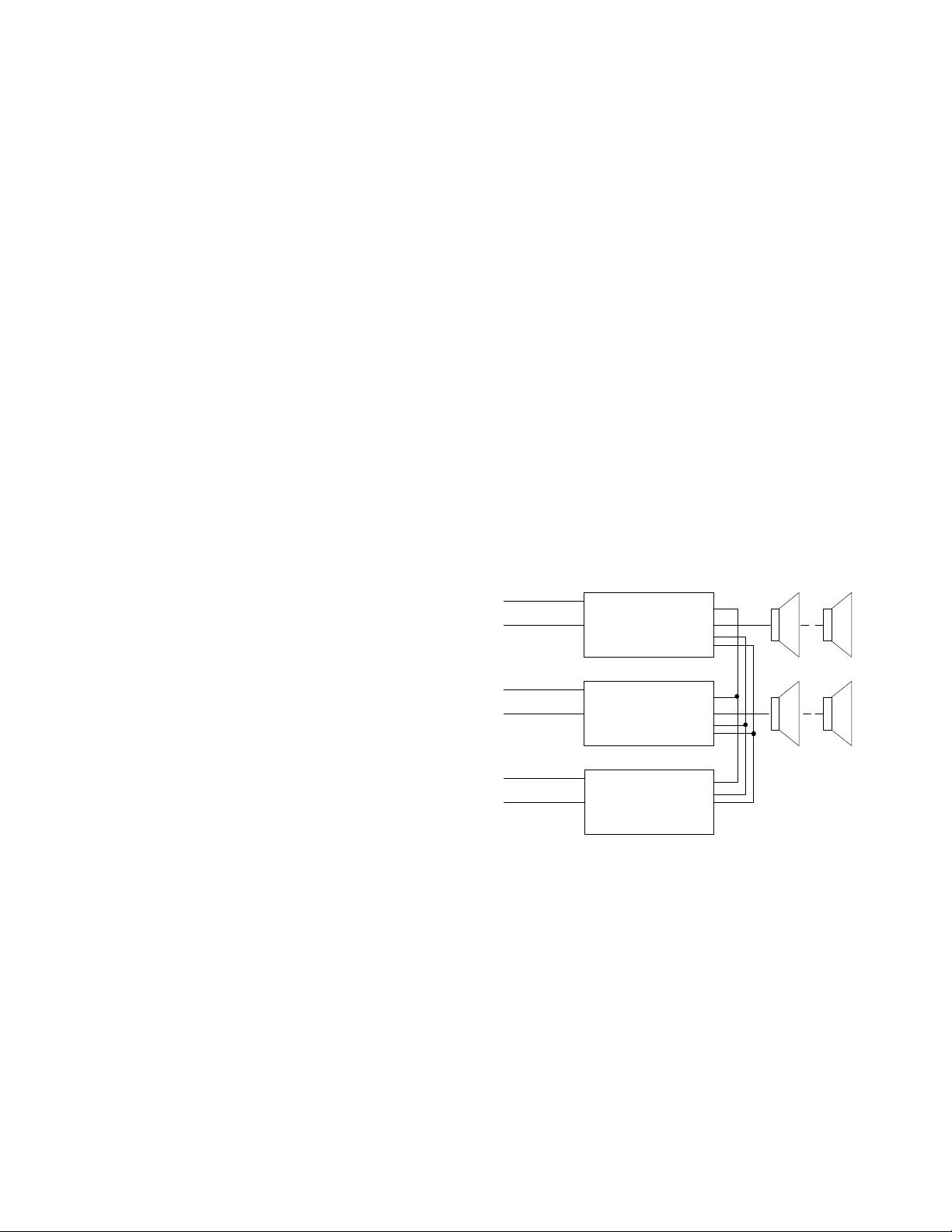
All call, if connected, will override both the music and
page inputs. All call requires an additional station port
for access and must be wired as shown in Figure 4-5.
When the all call station number is dialed any paging in
progress will be overridden and an alert tone will be
returned to the overridden parties. If they remain on the
line, on completion of the all call page, they will be
reconnected to their respective zones and all timers will
be reset, allowing a full page again on each zone.
TECHNICAL ASSISTANCE
When trouble is reported, verify that DC power is being
supplied to the unit. Assistance in troubleshooting is
available from the factory. When calling, you should
have a VOM and a test set available and be calling from
the job site. Call 1-540-427-3505 and ask for an
Applications Engineer.
CLARITY equipment is not field repairable. CLARITY
maintains service facilities in Roanoke, VA. Should
repairs be necessary, please call Clarity at 1-540-427-
3505 for a Return Authorization Number.
LIMITED WARRANTY
Clarity warrants its products to be free from defects in materials and workmanship under conditions of normal use and service for a period
of one year from the date of shipment. The obligation under this warranty shall be limited to the replacement, repair or refund of any such
defective device within the warranty period, provided that:
1. Inspection by Clarity indicates the validity of the claim;
2. The defect is not the result of damage, misuse, or negligence after the original shipment;
3. The product has not been in any way repaired by others and that factory sealed units are unopened (A service charge plus parts
and labor will be applied to units defaced or physically damaged);
4. Freight charges for the return of products to Clarity are prepaid;
5. All units " out of warranty" are subject to a service charge. The service charge will cover minor repairs (Major repairs will be subject
to additional charges for parts and labor).
This warranty is in lieu of and excludes all other warranties expressed or implied, and in no event shall Clarity be liable for any
anticipated profits, consequential damages, loss of time or other losses incurred by the buyer in connection with the purchase,
operation or use of the product.
This warranty specifically excludes damage incurred in shipment. In the event a product is received in damaged condition, the carrier should
be notified immediately. Claims for such damage should be filed with the carrier involved in accordance with the F.O.B. point.