Contents
1. Dimension ....................................................................................................................................................................3
2. Signal and Wiring .........................................................................................................................................................3
LED Indicator Definition ...................................................................................................................................................3
Pinout...............................................................................................................................................................................4
Connector X1 - DSUB 15 Male, to be connected to MR-J4 Servo Amplifier (4 wire –full duplex) ...............................4
Connector X1 - DSUB 15 Male, to be connected to MR-J4 Servo Amplifier (2 wire –half duplex)..............................4
Connector X2 - DSUB 15 Female, to be connected to BiSS C Encoder ......................................................................5
Shielding ..........................................................................................................................................................................5
Suggested Extension Cable.............................................................................................................................................5
Strain Relief .....................................................................................................................................................................5
Handling Precautions.......................................................................................................................................................5
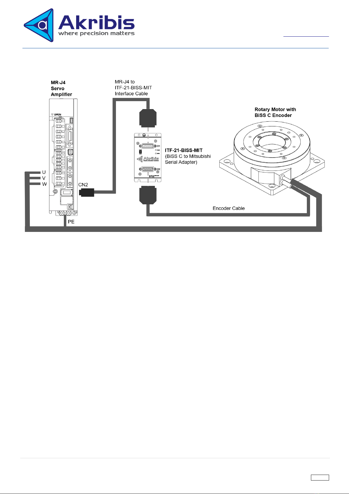
3. High Level Schematic of Typical Application................................................................................................................6
4. Quick-Start Guide.........................................................................................................................................................7
5. Architecture of Adapter.................................................................................................................................................9
BiSS C Interface ..............................................................................................................................................................9
Request Cycle Rate ...................................................................................................................................................10
Max Allowable BiSS C Cycle of Adapter ....................................................................................................................10
Default BiSS C Interface Setting of ITF-21-BISS-MIT................................................................................................11
Mitsubishi Serial Interface..............................................................................................................................................11
Adapter Alarm................................................................................................................................................................13
6. Setting Configuration..................................................................................................................................................13
Setting Supported ..........................................................................................................................................................14
7. ITF-21-BISS-MIT Firmware Version...........................................................................................................................19
8. PC Software: Interface Adapter Configurator.............................................................................................................19
Installation......................................................................................................................................................................19
Connection.....................................................................................................................................................................19
Setting Configuration .....................................................................................................................................................21
Firmware Download.......................................................................................................................................................23
Diagnostic ......................................................................................................................................................................25
BiSS C Cycle Period Calculation ...................................................................................................................................25
PC Software Version......................................................................................................................................................25
9. Document Revision History........................................................................................................................................26