Auvidea J20 Product manual

VERSION 1.0
J20 (38223)
J20
technical reference manual
38223
Version 1.0
Preliminary
November 2016
Auvidea GmbH
Kellerberg 3
D-86920 Denklingen
Tel: +49 8243 7714 622
www.auvidea.com!
AUVIDEA GMBH
TECHNICAL REFERENCE MANUAL
1

VERSION 1.0
J20 (38223)
Copyright Notice
Trademarks
NVIDIA, the NVIDIA logo, CUDA, Jetson, Maxwell,Tegra and VisionWorks are registered trademarks and/or
trademarks of NVIDIA Corporation in the United States and!other countries. Other company and product names
may be trademarks of the respective companies with which they are associated.
© Auvidea GmbH 2016
All Rights Reserved
No part of this document or any of its contents may be reproduced, copied, modified or adapted, without the
prior written consent of the author, unless otherwise indicated for stand-alone materials.
You may share this document by any of the following means: this PDF file may be distributed freely, as long as
no changes or modifications to the document are made.
Commercial use and distribution of the contents of this document is not allowed without express and prior
written consent of Auvidea GmbH.
AUVIDEA GMBH
TECHNICAL REFERENCE MANUAL
2

VERSION 1.0
J20 (38223)
Features
J20 six camera adapter module for the NVIDIA® Jetson™TX1 dev kit
The J20 adapter module is specifically designed for the TX1 dev kit. It plugs into the 120 pin CSI-2 camera
socket. Six 2 lane CSI-2 interfaces are provided. The 15 pin CSI-2 connector is compatible to the Raspberry Pi
camera connector. Up to six identical camera modules may be plugged in. To access all 6 cameras individually
3 I2C busses are used. Each bus connects to 2 connectors. To separate the 2 cameras on a single I2C bus, the
2nd connector (J2_x) is connected through an I2C address translation device. This changes the I2C address of
the camera so that 2 cameras can coexist on the same I2C bus.
Software drivers
The J20 is intended for software developers who wish to develop a software driver for setups with multiple
cameras.
•Ridgerun (ridgerun.com) is developing drivers for multiple Raspberry Pi camera setups. Please contact
Ridgerun for details.
•Raytrix (raytrix.de) is developing a driver for their C41 4k CSI-2 camera module. Please contact Raytrix for
details.
Status
Rev 1: 38223"
verylimitedsupply"
patch for power up reset of GPIO port expander
Rev 2: 38223-2"
firstsamplesendofNovember2016
AUVIDEA GMBH
TECHNICAL REFERENCE MANUAL
3

VERSION 1.0
J20 (38223)
I2C configuration
Example: Pi Camera 1.3 plugged into port J1_1!(I2C device 0)
$ i2cdetect -y -r 0
!!!!0 !1 !2 !3 !4 !5 !6 !7 !8 !9 !a !b !c !d !e !f
00: !!!!!!!!!-- -- -- -- -- -- -- -- -- -- -- -- --!
10: -- -- -- -- -- -- -- -- -- -- -- -- -- -- -- --!
20: -- -- -- -- -- -- -- -- -- -- -- -- -- -- -- --!
30: -- -- -- -- -- -- 36 -- -- -- -- -- -- -- -- --!
40: -- -- -- -- -- -- -- -- -- -- -- -- UU -- -- --!
50: -- -- -- -- -- -- -- -- -- -- -- -- -- -- -- --!
60: -- -- -- -- -- -- -- -- -- -- -- -- -- -- -- --!
70: -- -- -- -- -- -- -- — !
The „36“ is the hex address 0x36 and indicates that no driver is loaded yet. If a driver would have been loaded
it would show as „UU“ in location „36“.
Connecting the cable for the cameras or B101 modules
The cameras are connected with the standard 15 pin FFC cable with 1.0mm pitch. To plug in the cable just lift
the brown hatch of the connector, insert the cable the press the hatch down.
Note: please make sure that the contacts of the FFC cable face down. They have to be on the opposite
side of the brown hatch.
The cable is now safely locked in place. Some cables may have lengthy stiffeners on the opposite side of the
contacts. So it may be difficult to slide the cable in, as the connectors are placed close to each other. In this
case please use scissors to shorten the FFC cable. So contact length of 2mm is fine for the connectors on the
J20 module.
Auvidea supplies FFC cables with contact on the same side in various lengths.
Note: The Pi cameras and the B101 require FFC cables with contacts on the same side.!
#
port
I2C
device
CSI-2
bus
address
translation
Pi camera 1.3
Pi camera 2.1
B101
1
J1_1
0
CSI-A
-
0x36
0x64
0x0F
2
J1_2
6
CSI-C
-
0x36
0x64
0x0F
3
J1_3
2
CSI-E
-
0x36
0x64
0x0F
4
J2_1
0
CSI-B
✓
0x34
0x12
0x0D
5
J2_2
6
CSI-D
✓
0x34
0x12
0x0D
6
J2_3
2
CSI-F
✓
0x34
0x12
0x0D
AUVIDEA GMBH
TECHNICAL REFERENCE MANUAL
4

VERSION 1.0
J20 (38223)
Initialization
The J20 rev1 requires a supply of 1.8V from the dev kit board. This has to be enabled first by writing to the
GPIO port expander on the dev kit board. Rev 2 of the J20 features an on-board 1.8V LDO, so the enabling of
the 1.8V supply is not required. Please run the following commands every time after powering up the system,
so that the J20 is initialized.
i2cset -f -y 1 0x77 3 0xfb - enable 1.8V power to the J20 (rev 1 only)
i2cset -f -y 6 0x20 6 0x3e - configure the outputs of the I2C port expander
(low byte) - clock lines remain input, so there
is no data collision
i2cset -f -y 6 0x20 7 0x33 - configure the outputs of the I2C port expander
(high byte)!
i2cset -f -y 6 0x20 2 0xfe - write ones to all GPIO outputs and turn on LED
(low byte)
i2cset -f -y 6 0x20 3 0xff - write ones to all GPIO outputs !(high byte)!!!!
If the initialization commands above have been executed successfully the GPIO LED should be lighted up. The
power (PWR) LED should be always on. A Pi camera connected should respond to I2C accesses. We have tested
the port detection with i2cdetect. After init the GPIO port expander should show up on address 0x20 (device
6).
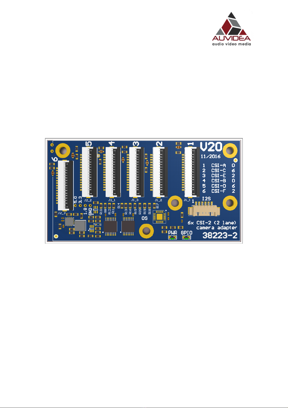
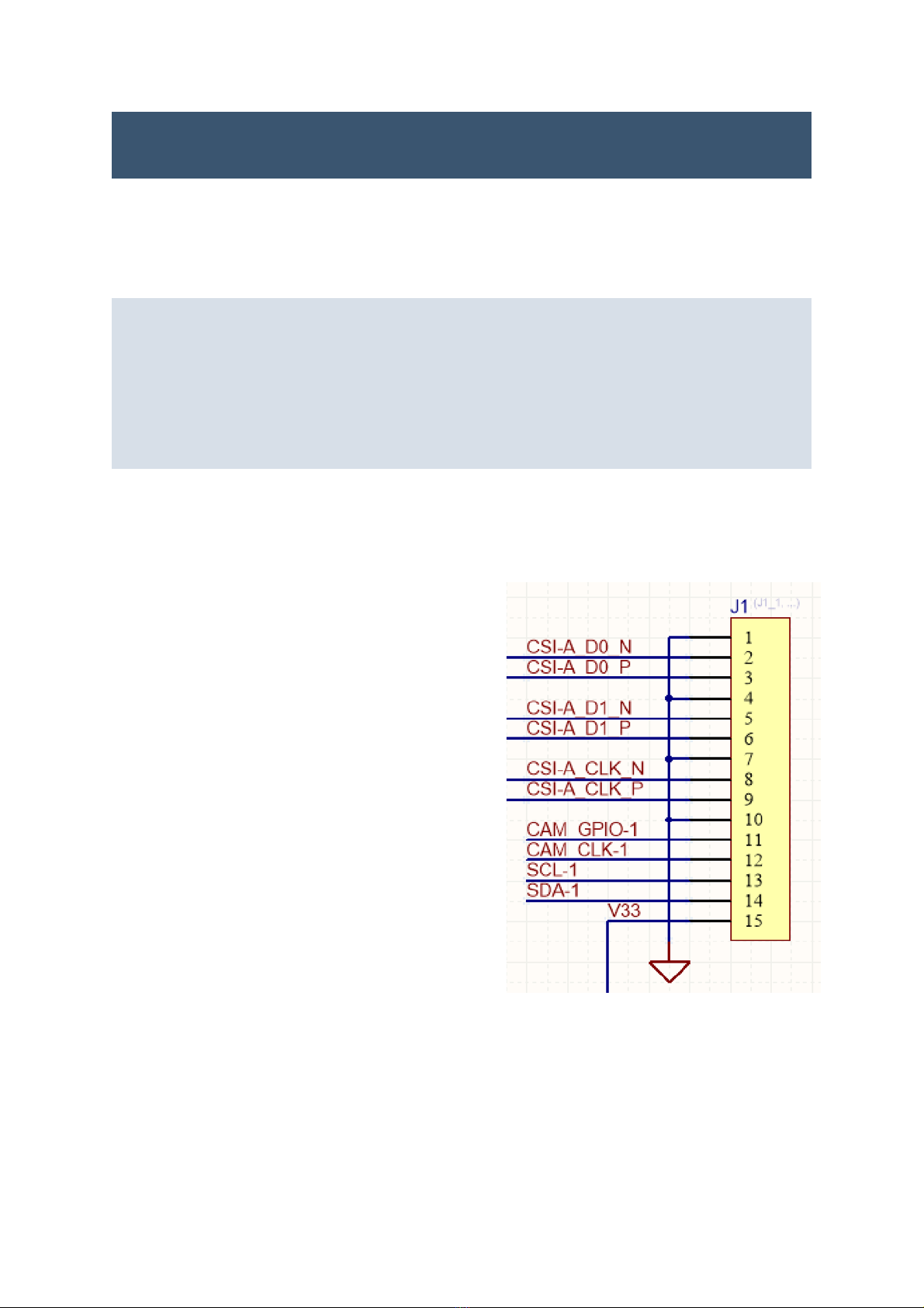
In the default configuration the J20 is configured that the
GPIO port expander only supplies the CAM_GPIO signal to
the CSI-2 connectors.
With the Raspberry Pi cameras the CAM_GPIO is the reset
to the camera. It must be inactive to allow the camera to
work.
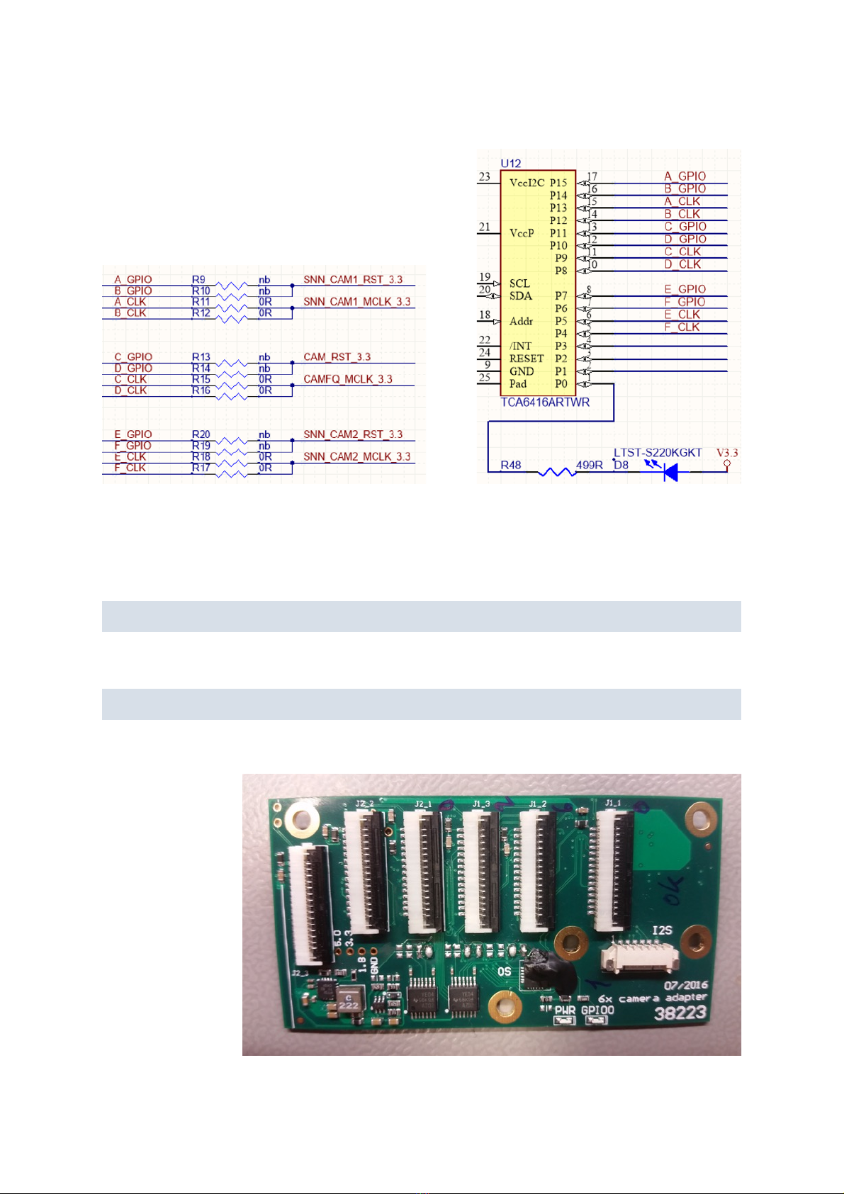
The CAM_CLK by default is connected to the CAM_CLK
signals of the 120 pin dev kit connector. So R11, R12, R15,
R16, R17, and R18 are installed. 0R resistors (0603 size) or
solder jumpers.
Please make sure that the on-board GPIO expander is
configured correctly with the i2cset commands as listed
above. The clock pins must be configured as inputs. If not
then the port expander will drive against the clock signals
of the dev kit board. This potentially could cause a
hardware damage.
AUVIDEA GMBH
TECHNICAL REFERENCE MANUAL
5

VERSION 1.0
J20 (38223)
Default configuration of the resistors:
CLK provided by the dev kit, GPIO by the GPIO board
expander.
If you want to modify the settings of the GPIOs to the 6 connectors just change the data in the following 2
commands:
GPIOs all 1:
i2cset -f -y 6 0x20 2 0xfe
i2cset -f -y 6 0x20 3 0xff
GPIOs all 0:
i2cset -f -y 6 0x20 2 0x00
i2cset -f -y 6 0x20 3 0x00
J20 rev 1
The „clock“ resistors
are equipped with
solder jumpers.
The black rubber
covers the power on
reset patch for the
GPIO port expander.
AUVIDEA GMBH
TECHNICAL REFERENCE MANUAL
6

VERSION 1.0
J20 (38223)
I2C address translation
Configuration resistors for the address translation
The J20 employs an address translation device to change the I2C
address for the 2nd connector (J2). This device is configured by 3
resistors (R1, R2 and R3).
By default the address translation is configured for cameras which
have a single I2C address. Cameras with multiple I2C addresses
may require a custom configuration of the three resistors (R1, R2,
and R3).
120 pin SAMTEC connector to the
TX1 dev kit
AUVIDEA GMBH
TECHNICAL REFERENCE MANUAL
7

VERSION 1.0
J20 (38223)
J20 rev 2
Rev 2 adds the power on reset circuitry and the 1.8V LDO. Also the silkscreen on top on bottom has been
extended.
top view:
bottom view:!
AUVIDEA GMBH
TECHNICAL REFERENCE MANUAL
8

VERSION 1.0
J20 (38223)
FAQ
1. to be added
!
AUVIDEA GMBH
TECHNICAL REFERENCE MANUAL
9

VERSION 1.0
J20 (38223)
Disclaimer
Thank you for reading this manual. If you have found any typos or errors in this document, please let us know.
This is the preliminary version of this data sheet. Please treat all specifications with caution as there may be
any typos or errors.
The Auvidea Team
AUVIDEA GMBH
TECHNICAL REFERENCE MANUAL
10

X-ON Electronics
Largest Supplier of Electrical and Electronic Components
Click to view similar products for Sockets & Adapters category:
Click to view products by Auvidea manufacturer:
Other Similar products are found below :
6508-0-00-01-00-00-33-0 AC164341 AC164348 1262 C8051F350-TB KITPF0100SKTEVBE LFVDBJR SK-AX2-CQ256-KITTOP
AC164334 AC164353 AC164383 SOCKET-ADM106XTQZ SPC564A80CAL176 ST5M1267-001 FP3-10PIN-ADAPTER-KIT CY3675-
LCC4A TDGL015 ATF15XXDK3-SAA100 LFBGADATC SM64TQ-ACTEL-1 AC164358 ATSTK600-RC99 76002056 DS91230+
OM13019,598 09185058 AC164369 AC164409 AC164402 SMPA-ISP-ACTEL-3-KIT ICESABCM81-01 LFVDBGF AC164408 KIT
70601-3 S5U13U00P00C100 AC164352 PN-Q208/5256V PN-T100/LC4256 AC164370 AC164355 AC164367 CY3675-TSSOP20B
SPC563M64AVB144 ATF15XXDK3-SAA44 AC164410 SPC563M64AVB176 SM132CQ-ACTEL AC164398 CX5103 IPC0165-S
This manual suits for next models
1
Table of contents