Classic AutoAir Mustang 1969 User manual

Installation Manual
1969-1970 Mustang
DOCUMENT #1-2027
©2012 ClassicAutoAir / 2.12vs3
©


You have just purchased the highest quality, best performing
A/C system ever designed for your Classic Vehicle.
To obtain the high level of performance and dependability our systems are known for, please pay close attention to the
following instructions. Our installation steps and procedures are derived from a long history of research and
development and the combined experience achieved thru thousands of successful installations (and feedback from
customers like you). Please remember that our #1 goal is that you’ll have a successful installation and a system that
performs at a very high level for many years to come.
Before starting, read the instructions carefully, from beginning to end, and follow the proper sequence. On the next
page you’ll find a safety and general checklist that you should read before starting your installation.
Again, thank you from our entire staff.
Congratulations...
www.classicautoair.com • 866.435.7801

The air conditioning system in your car is comprised of a compressor, condenser,
expansion valve, receiver/drier, and evaporator. Refrigerant (also known as Freon) is
compressed in the compressor and turns into a gas. In the condenser, this gas is cooled to a
liquid state and travels to the expansion valve. As the liquid refrigerant goes through the
expansion valve it rapidly cools in the evaporator. A fan blows over the evaporator and cools the
air that blows out your vents. The receiver-drier separates gas and liquid.
Evaporator with Blower Fan
In order to remove the heat from the air in the vehicle, the A/C
evaporator allows the refrigerant to absorb the heat from the air passing over it. The blower fan moves cool air out into the car
interior.
Compressor
The compressor pumps and circulates the refrigerant through the system.
Condenser
The condenser is a heat exchanger mounted at the front of the vehicle. Heat drawn out of the interior of
the car is expelled here.
Receiver/Drier
The drier not only dries refrigerant, it also filters the refrigerant and stores it under certain
operating conditions.
High Pressure Switch
A pressure switch is used to shut down the system if high or low pressure is
detected, basically it acts as a safety switch.
A Basic A/C Overview
www.classicautoair.com • 866.435.7801 • OVERVIEW
Receiver
Drier
Compressor
Evaporator Unit
Expansion Valve
Condenser
Suction
Valve Discharge
Valve
Firewall
OUTSIDE AIR
COLD AIR INTO VEHICLE
AIR FROM INSIDE VEHICLE
GROUND
POWER
SUCTION HOSE
DISCHARGE HOSE
LIQUID HOSE
1
1
2
3
4
5
2
3
4
5
COOLED AIR

Check List, Pre-Installation:
Procedures, During Installation:
Before beginning the installation check the shipping box for the correct components. YOUR BOXED UNIT INCLUDES A LIST OF
MAJOR COMPONENTS AND A LIST OF BAGGED PARTS. We have a 5 stage check process to make sure you have everything you’ll
need.
If your vehicle has been or is being modified, some procedures will need to be adjusted to fit your particular application.
A basic cleaning of the engine compartment and interior before beginning will make things go more smoothly.
Check condition of engine mounts. Excessive engine movement can damage hoses to A/C and/or heater.
Before starting, check vehicle interior electrical functions (interior lights, radio, horn, etc). Make a note of anything that does not work as
it’s supposed to. During the installation you might find the opportunity to repair or upgrade non-working or out of date components.
When you’re ready to start the installation, DISCONNECT THE BATTERY FIRST.
Drain the radiator. Retain the coolant and reuse, or dispose of properly.
SAFETY FIRST: Wear eye protection while drilling/cutting, deburr sharp edges, and never get in a hurry or force a part.
Tools: Your installation only requires the basic tools everyone has in their garage, nothing exotic or specific to A/C or Heat equipment.
Fittings: Use one or two drops of mineral oil (supplied with your kit) on ALL rubber o-rings, threads and rear of bump for o-ring where
female nut rides. Do not use thread tape or sealants.
Measure twice (or more), cut once
Should you have any technical questions, or feel you have defective components (or missing items), call us immediately,
we will be glad to assist you. Our toll-free number is listed on every page, we’re here to help!
YOU CAN NOW BEGIN THE INSTALLATION...
www.classicautoair.com • 866.435.7801 • CHECK LIST

Control & Operating Instructions
Your new Perfect Fit-Elite system offers complete comfort capabilities in
virtually every driving condition. This includes temperature control in all of the
modes. This system also provides the ability to blend the air between Face,
Heat, and Defrost modes simultaneously. To illustrate the various ways you can
adjust the airflow direction and temperature - we’ve provided these handy
illustrations and chart to show exactly how you can adjust your Perfect
Fit-Elite for maximum comfort...
Left Lever Postion
Distribution
Compressor State
1 2 3 4 5 6 7 8 9 10 11
Face A/C
100%
Defrost
100%
Floor
20%
Defrost
80%
Floor
40%
Defrost
60%
Floor
60%
Defrost
40%
Floor
80%
Defrost
20%
Face
80%
Defrost
20%
Face
60%
Defrost
40%
Face
40%
Defrost
60%
Face
20%
Defrost
80%
Floor
100%
FLOORDASH DEF
www.classicautoair.com • 866.435.7801 • PAGE 1
TEMP LEVER
FAN SWITCH
MODE LEVER
The FAN switch works like the OEM switch, the DOWN position is OFF
(all power to the system is OFF in this position).
There are 11 levels of adjustment within the range of the
DASH/FLOOR lever.
The COLD/HOT positions works like any traditional adjustment lever.
NOTE: When the TEMP lever is in the "FULL COLD" position the
compressor is ON, no matter what position the MODE lever is in (think
of it as a compressor-override function).
PERFECT
Elite
FIT
SERIES
ONON
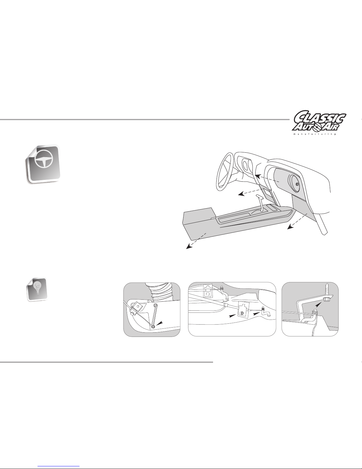
Remove Glovebox, Console (if
equipped), Facia, Radio and Bezel,
and set them aside for reinstall later
(see figure 1).
The removal of the Original Heater Assembly can be
accomplished by disconnecting three control cables. One is
attached to the Heat/Defrost door (see figure 2). One is
attached to the Temperature door, and one is attached to the
Vent / Heat door (see figure 3). Disconnect the electrical
harness from the assembly. Also remove attachment screw
located in front of the air inlet (see figure 4).
FIGURE 4
FIGURE 3
FIGURE 2
FIGURE 1
INTERIOR
COMPARTMENT
When retaining parts it’s a
good idea to store parts in a
zip lock bag, labeled with
info where the parts came
from and what size/type of
tool is needed to reinstall. Cleaning
the parts before you need to reinstall
them is a good idea too.
GOOD IDEA
www.classicautoair.com • 866.435.7801 • PAGE 2
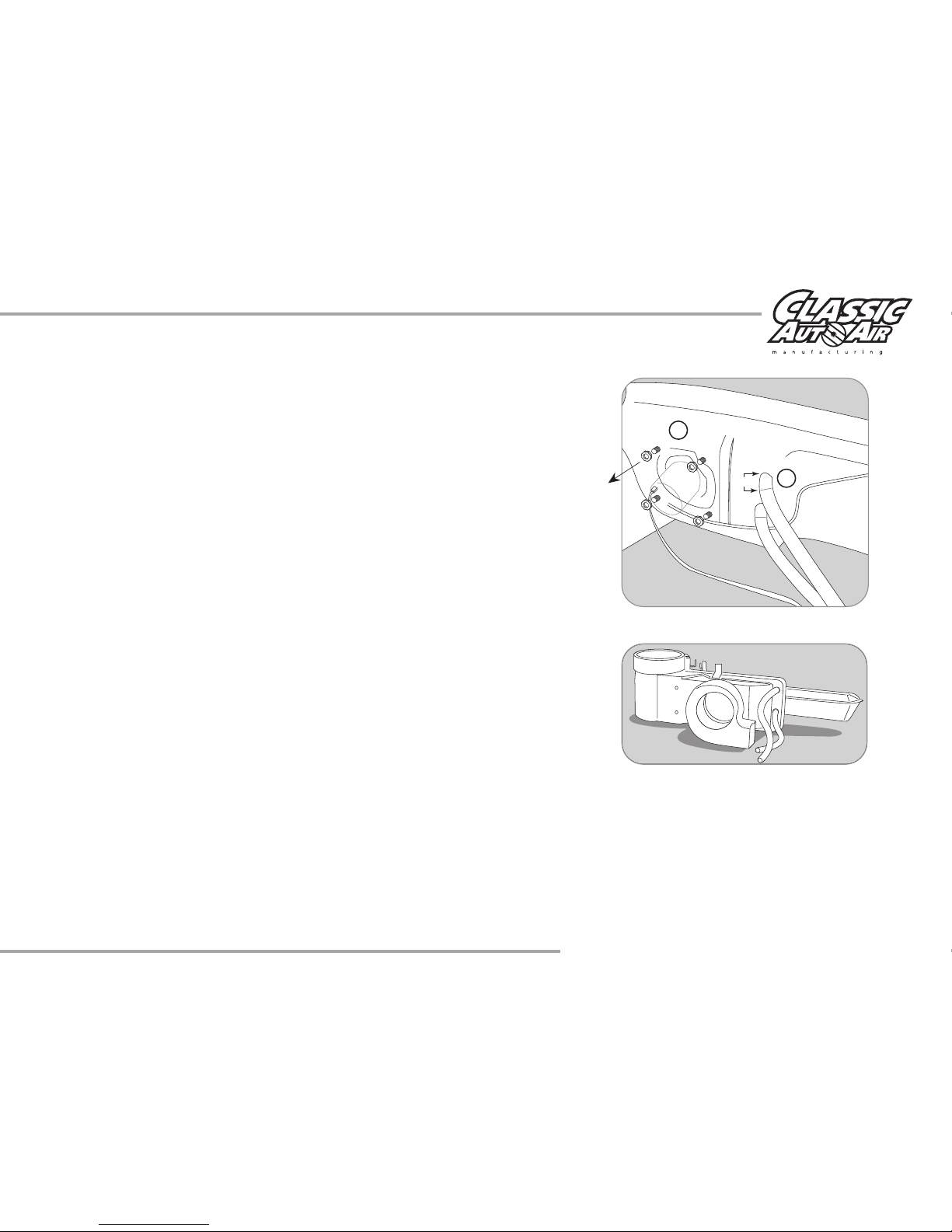
FIGURE 5
U
P
P
E
R
H
E
A
T
E
R
H
O
S
E
L
O
W
E
R
H
E
A
T
E
R
H
O
S
E
1"
A
B
FIGURE 6
OEM Heater Unit
(Not reinstalled)
BLOWER
MOTOR
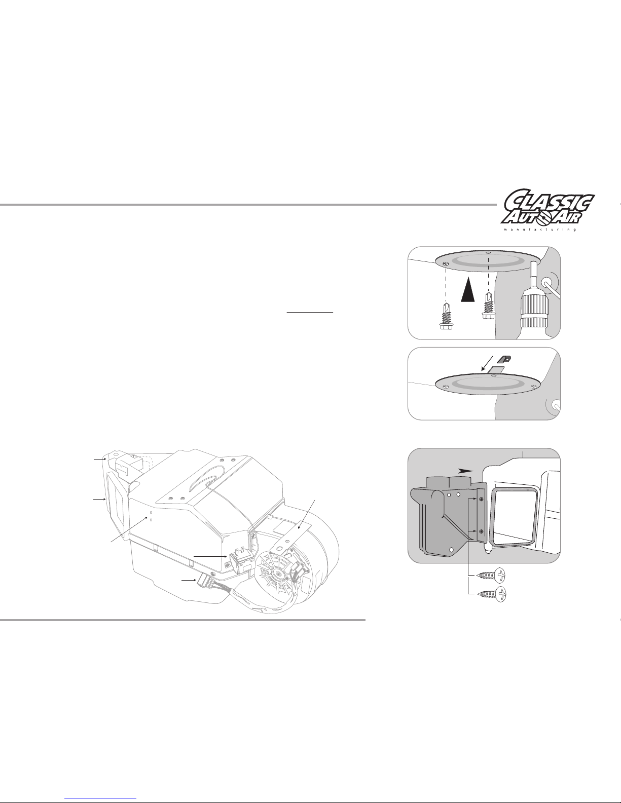
Locate blower motor on the firewall (Passenger Side) in the engine
compartment. Remove all 4 nuts around blower. Also disconnect the electrical
connector from the blower motor (see figure 5A). Cut wires at grommet in
firewall.
DRAIN COOLANT FROM RADIATOR and store safely to reuse or recycle
accordingly. Cut heater hose approximately 1” from firewall (see figure 5B). Also,
to prevent forgetting to refill the coolant when the installation is completed, do
not put the cap back into place - instead put the cap to the side and cover
radiator hole with a clean rag or something similar (this will help remind you to
add coolant before from starting the engine at the end of the installation).
www.classicautoair.com • 866.435.7801 • PAGE 3
NOTE: Illustrations NOT shown actual size
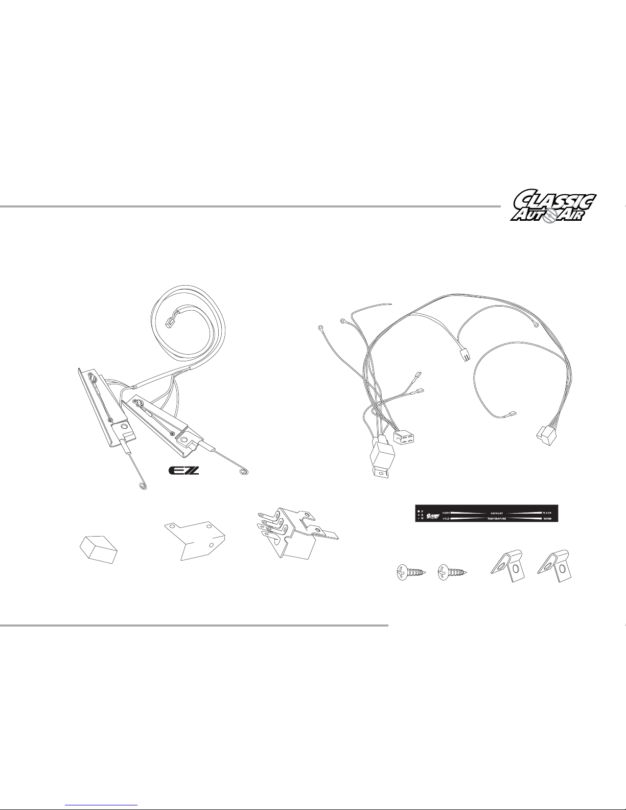
Blower Switch
Blower Switch Knob
Two #6 - 20x3/8" Screws
Faceplate Sticker
Two - Cable Clips
Wire Harness -
Power Supply
Cable Integrators
Ground Ground Ground
OEM Power
Supply
ECU
Pressure Switch
(engine compartment)
Thermostat
Relay
Blower Switch
Connection
Fan
Plug
Blower Switch Bracket
THESE ARE THE PARTS YOU WILL FIND IN BAG KIT A
You will use all of these parts and hardware during the next series of installation steps.
www.classicautoair.com • 866.435.7801 • PAGE 4
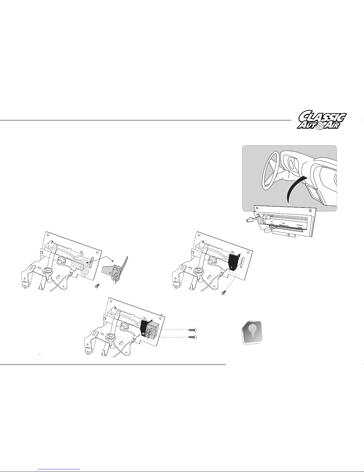
Remove The Heater Control Head From The Dash.
1) There are three OEM screws that hold your control head to the dash, one on
the lower side and two on the upper. Remove and retain these screws. Remove
the control head assembly (see figure 7).
2) Remove the OEM blower switch knob. Retain the screw, you will use it again
shortly. Remove the control cables and the original blower switch and set aside
(these will not be reused, see figure 8).
3) Attach the new blower switch bracket to the top part of the back of the face
plate (see figure 9-10), utilizing the OEM screw, and then attach the blower
switch to the bracket with the two supplied #6 - 20x3/8" screws. Reinstall the
switch knob.
Retain all the OEM parts that
you remove, at least until the
installation is completed.
GOOD IDEA
(OEM switch
not reinstalled)
Retain this
OEM screw
#6 - 20x3/8" Screws
FIGURE 8
FIGURE 7
FIGURE 9
FIGURE 10
www.classicautoair.com • 866.435.7801 • PAGE 5

FIGURE 11
FIGURE 13
MODE Control
TEMP Control
Attaching our exclusive cables to the
control head is accomplished in three easy
steps: Step 1) slide the include cable clips over
the ends of the of the EZ Integrators (as shown
in figure 11) then, Step 2) attach the integrators
to the OEM control head base with the OEM
screw you removed earlier, overlapping the
cable clamps (see figure 12). Step 3) push the
integrator wire ends over the ends of the levers
(see figure 13).
Once you have completed these steps, you
have just a few quick tasks before you can
reinstall the control head back into the dash.
We’ve included a new face sticker that
corresponds to the actions of your controls.
Make sure the surface is clean and oil free,
peel off backing and stick the sticker to the
control head face (this is optional of course,
but will be helpful, see figure 14).
Plug in the blower switch, and insert the entire
harness and control head back into dash
opening, resecuring with OEM screws.
OEM Screw
FIGURE 12
NOTE: The cable clips will overlap and use
the same hole and the single
OEM screw
FIGURE 14
www.classicautoair.com • 866.435.7801 • PAGE 6

Illustrations NOT shown actual size
Two 1/4 - #20 x 5/8" Bolts
Four #10 - 16 x 3/4" Tek Screws
Four #10 - 10 x 5/8" Phillips Screws
Evaporator Support Bracket
One Fresh Air Inlet Block Off
Defrost/Heat Duct Assembly One 1/2" WasherOne J-Clip
One Male Spade Connector
THESE ARE THE PARTS YOU WILL FIND IN BAG KIT B
You will use all of these parts and hardware during the next series of installation steps.
www.classicautoair.com • 866.435.7801 • PAGE 7

FIGURE 16
CAUTION! BRAKE LINE
You can now begin installing your Classic Air Perfect Fit Elite System.
FIGURE 15
4"
YOU CAN DRILL A
SMALL PILOT
HOLE IN THIS
LOCATION FIRST
WITH A SMALLER
DRILL BIT (LIKE 3/16"), THEN
PROCEED WITH THE 5/8" BIT
ONCE YOU KNOW YOU HAVE
CLEAR SPACE.
FIGURE 17
5/8" HOLE
HEATER MOTOR
HOLE
5/8"
1 3/8"
THIS IS
FROM THE
INSIDE
OF THE
CAR!
Locate the original wiring harness that supplied power to the original heater
motor (these wires were previously cut on the engine side of the firewall).
Reaching thru the glove box opening pull these wires out of their grommet.
Measure 4” from harness and cut both wires (see figure 15). On the OEM power
supply wire attach a 1/4” insulated male spade connector. Within the OEM fuse
box upgrade the factory HEATER fuse with a 20 amp fuse (VERY
IMPORTANT).
Locate the bottom left mounting hole in the firewall that attached the original
heater motor. From inside of the vehicle drill a 5/8" dia. hole for the drain tube.
TEMPLATE NOTIFICATION! A handy drilling template is included in this
manual (example shown in figure 16).
CAUTION: On the engine side of the firewall there is a brake line. Be
careful not drill through the brake line. It may be necessary to carefully
push this line out of the way, securing it a bit lower is usually all that is
necessary (see figure 17).
www.classicautoair.com • 866.435.7801 • PAGE 8
All preliminary
modifications to the
vehicle are complete.
TECH TIPS
Take a minute to familiarize yourself with the evaporator unit:
Evaporator
Support Bracket
Holes
Blower Motor Plug
Thermostat
Actuator Motor
Blower Motor
Bracket
Floor/Face
Vent Door
Locate the Fresh Air inlet block off. Install over hole in inlet cowl as shown on
the passenger side (see figure 18A). Attach with three #10 - 16 x 3/4" Tek
Screws. Locate the mounting tab location as shown and attach the 1/4" 20
J-clip supplied (see figure 18B).
Install a Fresh Air inlet block off over the vent opening at the drivers-side in the
same way, using the four OEM nuts.
Remove evaporator unit from box and place on a flat work surface.
Locate defrost / heat duct assembly and attach to the evaporator using two
#10 - 10 x 5/8" Phillips screws (see figure 19). NOTE: Be sure that the s-clips
are pushed over rear flange on evaporator.
Remove ECU from main unit and set aside.
FIGURE 18
FIGURE 19
A
B
www.classicautoair.com • 866.435.7801 • PAGE 9
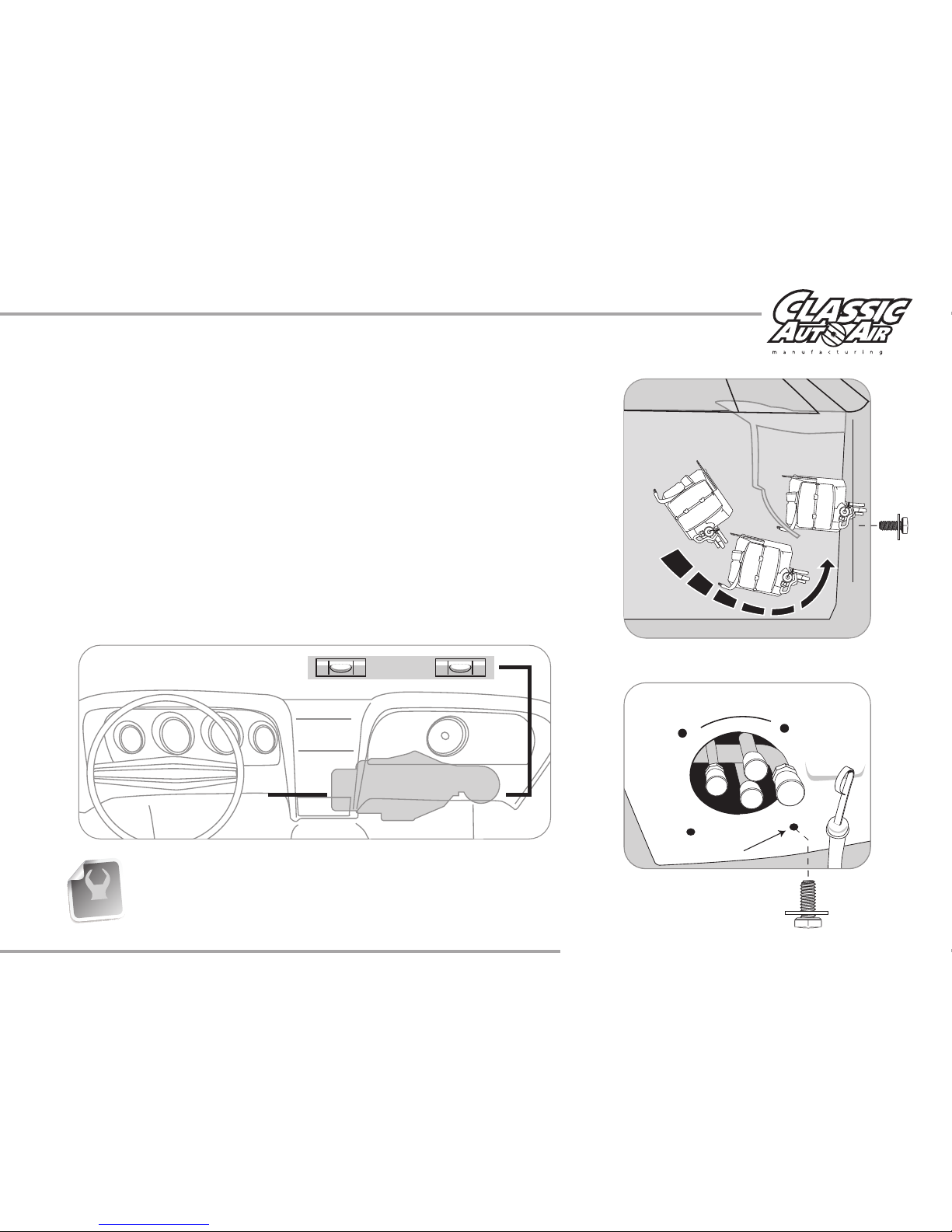
FIGURE 21
FIGURE 20
DASH
FIREWALL
1/4 - #20 x 5/8" bolts and
a 1/4” washer
Installing the complete evaporator unit under the dash will go much easier with
the help of a friend. One person can take the unit within the car and “roll” up
and under the dash while the other person can be ready at the firewall area with
one of the 1/4" - #20 x 5/8" bolts to secure the unit in place (see figure 20).
Now the unit will be easy to level and secure. Leveling the unit is very important
to insure proper drainage of condensation.
On back side of the evaporator is a mounting bracket with a 1/4"-20 J-clip. This
bracket will go flush with the inside firewall and you will secure the evaporator
by inserting one 1/4" - #20 x 5/8" bolt with a 1/4” washer (from the engine side)
using the bottom right hole (that originally attached the original heater assembly,
see figure 21).
Be sure to align the evaporator unit level with the bottom of instrument
panel (assuming the vehicle is sitting level) as shown above, but with a small
degree of tilt toward the back to allow proper drain of condensation.
TECH TIPS
www.classicautoair.com • 866.435.7801 • PAGE 10
LEVEL

FIGURE 23
#10 - 16 x 3/4" Tek Screw
FIGURE 22
The second 1/4 - #20 x 5/8" bolt attaches the blower motor mounting
bracket in the same location as the original heater mounting in front of the Air
Inlet. The blower support bracket will have an additional hole behind the 1/4 -
#20 x 5/8" Bolts. Install a #10 - 16 x 3/4" Tek screw through this hole and into
the cowling (see figure 22).
Locate in the Hardware Sack Kit the UPPER MOUNTING BRACKET and
attach to evaporator unit using two #10 - 10 x 5/8" Phillips screws. Attach
other end to the cowling with a #10 - 16 x 3/4" Tek Screw (see figure 23).
IMPORTANT NOTE: On the side of the main unit you will see several
holes for mounting holes... ONLY USE THE ONES IN THE CENTER FOR
THIS BRACKET! Do not tap into the other holes for any reason (see figure
24). Also, use a screwdriver and hand-power and do not over-tighten so you
don't strip the holes.
FIGURE 24
YES
NO!
NO!
#10 x 5/8"
Screws
www.classicautoair.com • 866.435.7801 • PAGE 11

THESE ARE THE PARTS YOU WILL FIND IN BAG KIT C
You will use all of these parts and hardware during the next series of installation steps.
Illustrations NOT shown actual size
Clear Plastic Drain Tube
Electronic Water Control Valve
Firewall Block Off
Two 1" Cap Plugs
Six Worm Gear Clamps
Refrigerant Tape
Two #10 - 16 x 3/4" Tek Screws
www.classicautoair.com • 866.435.7801 • PAGE 12
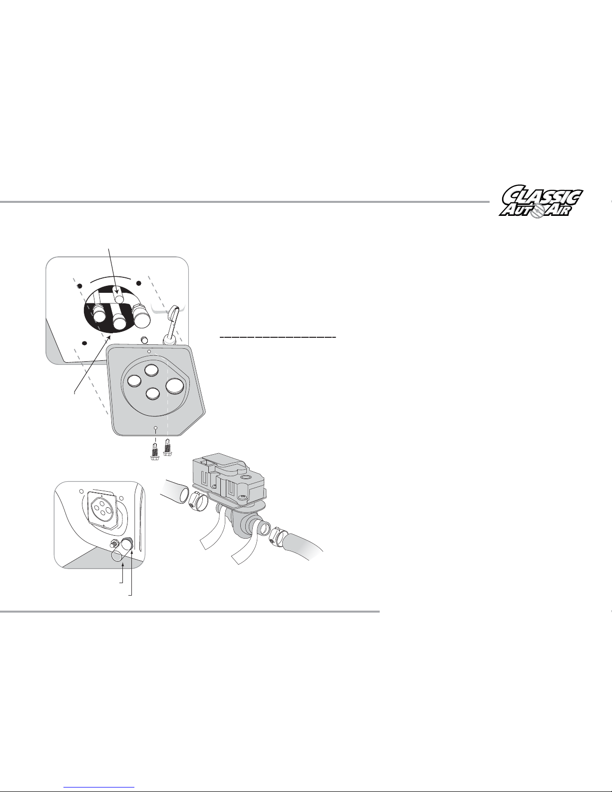
FIGURE 26
Refrigerant Tape
1/2" Clear Drain Tube
FIGURE 25
Water valve hose connects to this connection
This inlet is
connected
to the intake
manifold
In Bag Kit C you’ll find the firewall block off. Install this over the hose connections
coming thru the firewall within the engine compartment. Attach with two #10 - 16 x
3/4" Tek screws (Figure 25). Seal around the tubes with the included refrigerant tape.
This will keep unwanted moisture and debris from entering thru the firewall... so seal
carefully and thoroughly.
IMPORTANT NOTICE
Classic Auto Air has done extensive testing on the
correct method to install the water valve in order to get a repeatable and progressive
temperature control.
The water valve must be installed per these instructions!....
The lower connection on the tubes coming thru the block off assembly is going to be
routed to the water outlet on the intake manifold. Attach your hose with cable clamps
on both ends and route where it will not intefere with linkage or come in contact with
exhaust manifolds or headers.
The upper port coming thru the firewall will be routed to and thru your new your
electronic water valve (the water valve is marked for easy installation). First Attach
a 6” piece of 5/8” dia. heater hose with the supplied worm gear clamp. Attach
to the inlet side of the water valve using another supplied hose clamp.
Attach a heater hose from the outlet side of the electronic water valve
and route to the connection on the water pump.
Insert a 6" piece of the clear, 1/2" drain tube we included
through the hole previously drilled and attach over the
drain nipple (see figure 26). Seal around tube with
refrigerant tape.
W
A
T
E
R
P
U
M
P
H
E
A
T
E
R
C
O
R
E
www.classicautoair.com • 866.435.7801 • PAGE 13

THESE ARE THE PARTS YOU WILL FIND IN BAG KIT D
You will use all of these parts and hardware during the next series of installation steps.
Illustrations NOT shown actual size
Five #10 - 16 x 3/4" Tek Screws
Wire Harness System
FACE/FLOOR
POWER
CONTROL
WATER VALVE
DEFROST
The ECU will be found
in it’s own box
Yellow
Blue
Orange
www.classicautoair.com • 866.435.7801 • PAGE 14

We’ve included enough wire length to allow you to mount the ECU in a variety
of places. It is very important that you mount this in a place where it will stay dry
and that vibration is at a minimum. Also make sure that where ever you mount it
does not interfere with any moving controls or cables. We recommend
mounting it just above the right hand side of the main unit using the included
tek-screws. IMPORTANT! DON’T MOUNT THE ECU PERMANENTLY JUST
YET. THAT CAN BE DONE AFTER YOU CALIBRATE THE UNIT (SEE
NEXT PAGE).
In Bag Kit D you will find three wiring harnesses with connections at each end.
Plug the harness with YELLOW band into the YELLOW ECU port and the other
end into the servo motor on the main unit (motor is marked with YELLOW
INDICATOR). Repeat this process for the other two harnesses, following the
color coding indicated on cables and ports. Attach cable in the engine
compartment to the electronic water valve (see figure 27). Using one of the CAP
PLUGS provided, slot it and install over the heater hose/cable.
NOTE: The GREEN harness connection will be made from the harness you
previously installed, just plug the loose connection in the CONTROL
port on the ECU.
FACE/FLOOR
POWER
CONTROL
WATER VALVE
DEFROST
INSTALL (2)
1” dia. CAP PLUGS
OVER HOLES.
SLOT ONE FOR THE CABLE.
FIGURE 27
FIREWALL
www.classicautoair.com • 866.435.7801 • PAGE 15
This manual suits for next models
1
Table of contents
Popular Automobile Part manuals by other brands


Edelbrock
Edelbrock Russell R08367 installation instructions

FILTRON
FILTRON PS 974/1 Installation instruction

Dinan Tronics
Dinan Tronics D440-0052 installation instructions

Edelbrock
Edelbrock Performer 1403 owner's manual

Edelbrock
Edelbrock 7798 installation instructions

Edelbrock
Edelbrock 3862 installation instructions