manuals.online logo
Brands
  1. Home
  2. •
  3. Brands
  4. •
  5. Claypaky
  6. •
  7. Projector
  8. •
  9. Claypaky V.I.P. DIA User manual

Claypaky V.I.P. DIA User manual

ENGLISH
®
ENGLISH
V.I.P. DIA
SAFETY INFORMATION
1
UNPACKING AND PREPARATION
2
INSTRUCTIONS MANUAL
Carefully read this instructions manual in its entirety and keep it safe for future
reference.
It is essential to know the information and comply with the instructions given
in this manual in order to ensure the fitting is installed, used and serviced
correctly and safely.
CLAY PAKY S.p.A. disclaims all liability for damage to the fitting or to other
property or persons deriving from installation, use and maintenance that have
not been carried out in conformity with this instructions manual, which must
always accompany the fitting.
CLAY PAKY S.p.A. reserves the right to modify the characteristics stated in
this instructions manual at any time and without prior notice.
Congratulations on choosing a Clay Paky product! We thank you for your
custom. Please note that this product, as all the others in the rich Clay Paky
range, has been designed and made with total quality to ensure excellent
performance and best meet your expectations and requirements.
HTI / HMD 300
• Maximum ambient temperature
For the fitting to operate well and reliably, the ambient temperature should not
exceed 35°C (95°F).
• IP20 protection rating
The fitting is protected against penetration by solid bodies with a diameter of over
12 mm (0.47”) (first digit 2), but not against dripping water, rain, splashes or jets of
water (second digit 0).
• Protection against electrical shock
This fitting is classified, in accordance with the type of protection against electrical
shock, in Class I. It must therefore be connected to a power supply system with
efficient earthing.
It is, moreover, recommended to protect the supply lines of the projectors from
indirect contact and/or shorting to earth by using appropriately sized residual current
devices.
• Hooking up to the supply mains
The operations for connecting to the electricity mains must be carried out by a
qualified electrical installer.
Check that the mains frequency and voltage correspond to the frequency and
voltage for which the projector is designed, given on the electrical data label.
This label also gives the input power. Refer to this to evaluate the maximum number
of fittings to connect to the electricity line in order to avoid overloading.
• Unpacking
Open the cardboard box, take out
the polystyrene wrapping and
separate it, freeing the projector.
Remove the plastic bag from the
projector and position this on a
horizontal top.
• Packing contents
Besides the projector, the packing also
contains the following accessories:
- Bracket code 173008/001 (1).
- 2 countersunk head screws
M6x10 mm code 020005/021 (2).
- 2 countersunk washers
code 020214/001 (3).
- Hexagonal wrench 4 mm
code 050004 (4).
- 2 accessory holder guides of standard
length 170 mm code 173007/801 (5).
- Double ended wrench 7/8 mm
code 050003 (6).
- Wrench 16 mm cod. 750467/001 (7).
- Standard lens 1:2.4/100mm
code 173040/801 (8).
- Lens mounting code 173051/801 (9).
- Lens hood plate code 173017/001 (10).
- Socket for mounting on cable
code 030210 (11).
- This instructions manual
code 099575 (12).
5
• Installation
Make sure all the parts for fixing the projector are in a good state of repair.
Make sure the point of anchorage is stable before positioning the projector.
• Minimum distance from illuminated objects
The projector needs to be positioned so that
the objects hit by the beam of light are at least
1 metre (3’3”) from the lens of the projector.
• Minimum distance from flammable materials
The projector must be positioned so that any flammable materials are at least
0.10 metres (4”) from every point on the surface of the fitting.
It is permissible to mount the fitting on normally flammable surfaces.
• Maintenance
Before starting any maintenance work or cleaning the projector, cut off power from
the supply mains.
After switching off, do not remove any parts of the fitting for 4 minutes. After this time
the likelihood of the lamp exploding is virtually nill. If it is necessary to replace the
lamp, wait for another 15 minutes to avoid getting burnt.
The fitting is designed to hold in any splinters produced by a lamp exploding.
The lenses must be mounted and, if visibly damaged, they have to be replaced with
genuine spares.
• Temperature of the external surface
The maximum temperature that can be reached on the external surface of the fitting,
in a thermally steady state, is 100°C (212°F).
• Lamp
The fitting mounts a high-pressure lamp that needs an external igniter.
This igniter is fitted onto the fitting.
- Carefully read the "operating instructions" provided by the lamp manufacturer.
- Immediately replace the lamp if damaged or deformed by heat.
The products referred to in this manual conform to the
European Community Directives to which they are subject:
• Low Voltage 73/23
• Electromagnetic Compatibility 89/336
12
(3’3”)
1.0 HTI/HMD 300
5
2
3
4
1
6
78
9
10
11
• Fitting the accessory holder guides
Screw the two accesssory holder guides (5) into the threaded hole of the inserts
(17), and tighten them appropriately with the 8 mm double ended wrench (6)
supplied.
IMPORTANT: during this
operation, take care not to
turn the inserts (17) by
blocking them in their
position with the 16 mm
special wrench (7) also
supplied.
The accessory holder
guides (5) are electrified at
an extra-low safety voltage
(24V ac) and protected
against short-circuiting.
This permits installing the
entire range of motor driven
and timed accessories
available.
6
• Fitting projector mounting
Position the bracket (1) on the plates
(13) according to the desired height.
In correspondence with the chosen
hole, place the countersunk washers
(3) and the screws (2), then lock it all
with the aid of the Allen wrench
supplied (4).
Adjust the projector mounting in the
desired position and lock it with the
knobs (14).
The bracket (1) can also be fitted towards the bottom of the projector.To do this, it is
necessary, before fitting the bracket, to extract the knobs (14) from the rear hole and
turn through 180° both the plates (13) and the spacers (15), then put the knobs (14)
back into the front hole
.
IMPORTANT: The central screw (16) must never be removed so as not to jeopardize
the balance of the projector on the mounting.
•
Fitting the lens hood on the lens holder
If you wish to fit the lens hood
plate (10) on the lens mounting
(9), take out the 3 screws (19)
with the aid of a Phillips
screwdriver. Position the lens
hood plate (10) on the cover ring
(20) of the lens mounting (9)
and put back in the 3
screws (19) tightening
them appropriately.
• Fitting the lens
Insert the lens (8) into the mounting
(9) and tighten the handwheel (21).
Rest the lens mounting on the guides
(5) and lock it by turning the fixing
clips (22) inwards until they clip on.
In addition to the lens supplied as
standard there is a vast range of
optional lenses.
• Fitting accessories for special
effects
Fit the desired accessories on the
guides, referring to the assembly
instructions provided with the
accessories.
• Inserting the lamp
Refer to the instructions for opening the projector and changing the lamp in paragraph
4 MAINTENANCE.
INSTALLATION
3
• Installing the projector
The fitting must only be secured with
the specific mounting, through the hole
in the bracket (1).
It is recommended to use a screw ø10
with nut and spring washer
.
• Mains power connection
The projector has to be hooked up to the electricity mains via the specific socket (11)
supplied.
L
N
• Switching on the projector
After carrying out all the above operations, press the switch (18) checking that the
projector works properly.
11
18
Mains
59
2221
8
3
2
13
14
11
131615 14
15
16
14
13
91910 20
19
17
7
6
5
3°
Y
X
X
Y
7
ENGLISH
MAINTENANCE
4
• Opening and closing the
projector
Loosen the handwheels (24) and
remove the re-lamping cover (25)
from the projector.
After maintenance, fit the cover (25)
back on and lock the handwheels (24).
• Re-lamping
After opening the projector, loosen
the two side ring nuts (26) of the
lamp to replace and remove it from
the mountings (27).
Take the new lamp out of its package,
loosen the two side ring nuts (26) and
insert it in the mountings (27), then
screw the fixing ring nuts back on
.
WARNING: Do not touch the
lamp’s bulb with bare hands.
Should this happen, clean the bulb
with a cloth soaked in alcohol and
dry it with a clean, dry cloth.
IMPORTANT: To distribute the beam
of light uniformly, the lamp needs to
be positioned with the protrusion (28)
visible on the bulb outside the optical
axis of the projector. For this purpose
it is recommended to turn the
protrusion towards towards the top
cover (25) of the projector .
• Replacing fuses
To replace the fuses press the tab
(29) and take out the fuse-holder box
(30). Replace the broken fuses with
new ones of the type described on
the label (31) on the fuse-holder box
(30). Put it back in so the tab clicks
home (29).
FUSE
5 x 20
5AT
250V
• Periodical cleaning
To keep the luminous efficiency of the projector unchanged, it is vital to periodically
clean the parts where dust and grease can accumulate.
Observing the following guidelines will help keep the projector in perfect working
order for a long time.
To remove dirt from the lens, use a soft cloth dampened with any liquid detergent for
cleaning glass.
Caution: Never use solvents or spirits.
Parts requiring frequent cleaning.
Parts requiring monthly cleaning.
31 29
30
• Centring the projector
Slightly undo the mounting screw (23), move the projector horizontally, turning the
beam of light in the desired direction, then re-tighten the mounting screw.
Loosen the knobs (14), move the projector vertically on the bracket (1) to position the
beam of light at the desired point, then lock the knobs (14).
• Centring the lens
Move the lens (8) and/or lens holder (9) axially to obtain perfect focusing.
• Rotating the axis of projection
The holes on the bracket (1) for fixing the plates (13) are appropriately slotted to
permit rotating the fitting on its axis by approximately 3°.This permits fine adjustment
of the angle of the image projected, which is useful when using some particular
accessories such as for slide or gobo projection.
Using the hexagonal wrench (4) supplied, loosen a screw (2) and turn the projector
to the position required, and then re-tighten the screw (2).
23
14
1
13
1
9
8
2
4
24 25 24
2628
26
27
8
TECHNICAL DATA
6
Power supplies available
• Version with built-in power factor
correction:
- 220 - 240V 50Hz
- 200V 50Hz - 230V 60Hz
- 200 - 220V 60Hz
- 260V 50Hz
• Version without built-in power factor
correction:
- 220 - 240V 50Hz
- 200V 50Hz - 230V 60Hz
- 200 - 220V 60Hz
- 260V 50Hz
- 120V 60Hz
- 100V 50Hz
- 100V 60Hz
The projector is designed to operate at
the mains frequency and voltage given
on the electrical data label on the back
of the appliance.
Input power
• Versions with built-in power factor
correction: 450VA at 230V 50Hz
(standard power factor correction 35µF).
• Versions without built-in power factor
correction:
800VA at 230V 50Hz.
Lamp
Metal halide supplied with special
built-in power supply unit.
• Type HTI 300W
- Connection SFc 10-4
- Colour temperature 6,500 K
- Luminous flux 22,000 lm
- Average life 750 h
- Any working position
• Type HMD 300W
- Connection SFc 10-4
- Colour temperature 5,700 K
- Luminous flux 20,000 lm
- Average life 3,000 h
- Working position p45
Optical unit
• Base in die-cast aluminium.
• Twin lens condenser.
• Spherical reflector with a high
luminous efficiency.
Lens units
• Standard: 1:2,4/100 mm (30,9°)
• Optional: 1:2,8/45 mm multi-lens (64,2°)
• Optional: 1:2,8/60 mm multi-lens (45,8°)
• Optional: 1:2,8/85 mm multi-lens (34,4°)
• Optional: 1:2,8/120 mm multi-lens (24,1°)
• Optional: 1:3,5/150 mm multi-lens (19,5°)
• Optional: 1:4/165 mm (17,2°)
• Optional: 1:4,4/200 mm (14,3°)
• Optional: 1:3,5/70÷120 mm zoom (39,5°÷22,9°)
Safety Devices
• Power supply automatically cut off in
the event of overheating.
• Power supply cut off on opening the
cover.
•Short-circuiting protection on the
accessory holder guides.
Cooling
By forced ventilation with the axial fan
(projector body) and radial fan (slide
holder accessory).
Body
• In die-cast and extruded aluminium.
• Epoxy powder painting.
Mounting
• Bracket in steel painted with epoxy
powders.
• Three installation positions with a step
of 25 mm (0.98”).
• Bracket adjustable on 120°.
Working position
Operation in any position, limited to the
specifications of the lamp used.
Weights and dimensions
Versions 200-240V with PFC: 7,8 kg
(17 Ibs 3 ozs).
Versions 200-240V without PFC: 7,3 kg
(16 Ibs 1 ozs)
.
Versions 100-120V without PFC: 10,2 kg
(22 Ibs 7 ozs).
A
At
(10.04”) 255
(12.09”) 307
(6.38”)
162
(8.07”)
205
(6.69”)
170
At
A
21.22”
539 mm
14.84”
377 mm
200-240V
with PFC
18.98”
482 mm
12.60”
320 mm
200-240V
without PFC
21.22”
539 mm
14.84”
377 mm
100-120V
without PFC
TROUBLESHOOTING
5
No mains supply. Check the supply socket is
powered and/or fuse
conductivity.
THE PROJECTOR WILL NOT SWITCH ON
NO MOTOR-DRIVEN ACCESSORY WORKS
TROUBLE
DEFECTIVE PROJECTION
REDUCED BRIGHTNESS
POSSIBLE CAUSES CHECKS AND REMEDIES
•
••
••••
•
Lamp exhausted or defective. Replace the lamp.
(See instructions).
No power on the guides. Call an authorized technician.
The accessory motors fail to
work. Call an authorized technician.
Lenses or reflector broken. Call an authorized technician.
Dust or grease deposited. Clean. (See instructions).

Other Claypaky Projector manuals

Claypaky STAGE COLOR 1200 User manual

Claypaky

Claypaky STAGE COLOR 1200 User manual

Claypaky SPHERISCAN C11260 User manual

Claypaky

Claypaky SPHERISCAN C11260 User manual

Claypaky PIPER MS HTI 150 User manual

Claypaky

Claypaky PIPER MS HTI 150 User manual

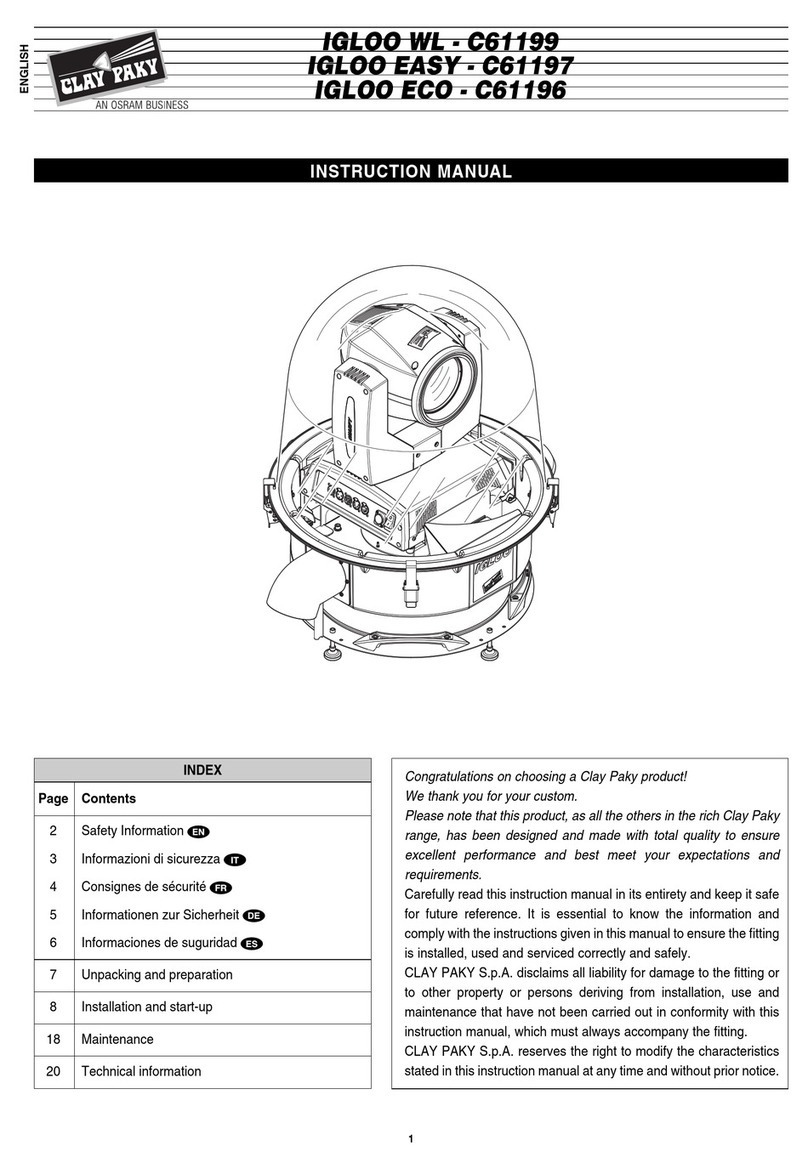
Claypaky IGLOO WL - C61199 User manual

Claypaky

Claypaky IGLOO WL - C61199 User manual

Claypaky C61415 User manual

Claypaky

Claypaky C61415 User manual

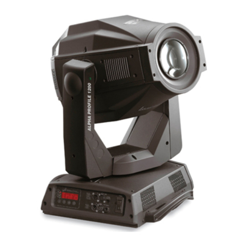
Claypaky ALPHA PROFILE 1200 User manual

Claypaky

Claypaky ALPHA PROFILE 1200 User manual

Claypaky C52159 User manual

Claypaky

Claypaky C52159 User manual

Claypaky STORMY User manual

Claypaky

Claypaky STORMY User manual

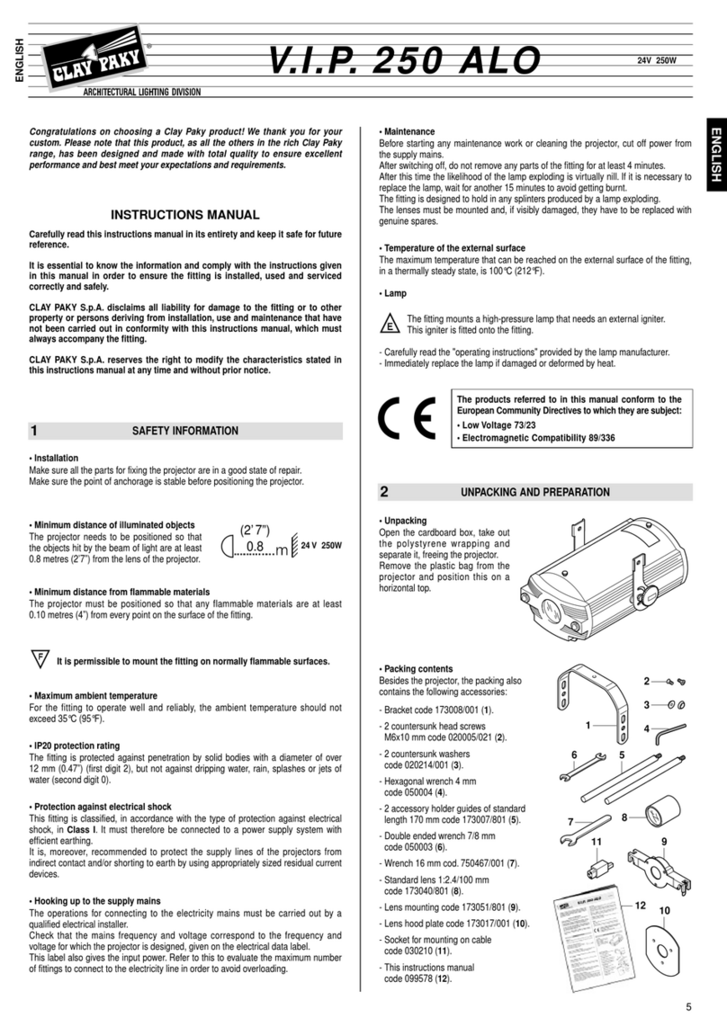
Claypaky V.I.P. 250 ALO User manual

Claypaky

Claypaky V.I.P. 250 ALO User manual

Claypaky V.I.P. HTI 300 User manual

Claypaky

Claypaky V.I.P. HTI 300 User manual

Claypaky HEPIKOS User manual

Claypaky

Claypaky HEPIKOS User manual

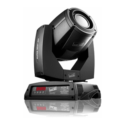
Claypaky ALPHA SPOT 300 User manual

Claypaky

Claypaky ALPHA SPOT 300 User manual

Claypaky CL3014 User manual

Claypaky

Claypaky CL3014 User manual

Claypaky A.LEDA WASH K10 W User manual

Claypaky

Claypaky A.LEDA WASH K10 W User manual

Claypaky V.I.P. 150 PFC User manual

Claypaky

Claypaky V.I.P. 150 PFC User manual

Claypaky RAIN SPOT 575 User manual

Claypaky

Claypaky RAIN SPOT 575 User manual

Claypaky MINISCAN HMD 300 User manual

Claypaky

Claypaky MINISCAN HMD 300 User manual

Claypaky Sharpy User manual

Claypaky

Claypaky Sharpy User manual

Popular Projector manuals by other brands

Ask Proxima A1100 Specifications

Ask Proxima

Ask Proxima A1100 Specifications

Eiki EK-501W Service manual

Eiki

Eiki EK-501W Service manual

3M MP225 Operator's guide

3M

3M MP225 Operator's guide

Panasonic PTL501XU - LCD VIDEO PROJ operating instructions

Panasonic

Panasonic PTL501XU - LCD VIDEO PROJ operating instructions

Toshiba TLP-WX100U - TLP WX100 WXGA LCD Projector Specifications

Toshiba

Toshiba TLP-WX100U - TLP WX100 WXGA LCD Projector Specifications

Barco OV-508 Specifications

Barco

Barco OV-508 Specifications

Barco DP2K-19B installation manual

Barco

Barco DP2K-19B installation manual

Christie CP2230 user manual

Christie

Christie CP2230 user manual

Barco DP2K SLP Series User and installation manual

Barco

Barco DP2K SLP Series User and installation manual

LG Minibeam Pro PF1500 Service manual

LG

LG Minibeam Pro PF1500 Service manual

UUO P6 PRO user manual

UUO

UUO P6 PRO user manual

Sony VPL-X600U Mk II Service manual

Sony

Sony VPL-X600U Mk II Service manual

Panchromatic Eumig S 810D user manual

Panchromatic

Panchromatic Eumig S 810D user manual

InFocus IN114xv manual

InFocus

InFocus IN114xv manual

Panasonic PT-RQ32KE operating instructions

Panasonic

Panasonic PT-RQ32KE operating instructions

Optoma TS526 Specifications

Optoma

Optoma TS526 Specifications

Mitutoyo PJ300 quick start guide

Mitutoyo

Mitutoyo PJ300 quick start guide

Epson PowerLite S27 user guide

Epson

Epson PowerLite S27 user guide

manuals.online logo
manuals.online logoBrands
  • About & Mission
  • Contact us
  • Privacy Policy
  • Terms and Conditions

Copyright 2025 Manuals.Online. All Rights Reserved.