Clear Water Audio CWC-3D User manual

Installation Manual
CWC-3D Headrest Speakers
(1990-1997½ MX-5 / Miata Sound Systems)

Page 2
Step 1: Parts and Overview
Congratulations on your purchase of the ultimate car audio upgrade
available for the Mazda Miata/MX-5!
Below are some of the features associated with this speaker component set:
• This system was specifically designed for the Miata/MX5.
• Hundreds of hours have gone into the testing and design of this audio system.
• Measurements were made with the industry’s top equipment.
• No other speakers in the world have been so meticulously designed
specifically for one vehicle.
• The system was designed so that anyone can install it with minimal tools.
• There is no need to do any drilling, cutting, tearing or splicing with this
install. This will keep your factory warranty intact.
• As with all Clearwater purchases your satisfaction is guaranteed!!
Important Note:
Some Miatas came with incorrectly wired headrest speakers from the factory.
The only easy way to know is replace the entire headrest harness with the
Clearwater full harness.
Please be sure to read our instructions thoroughly before
attempting installation.
Parts Included:
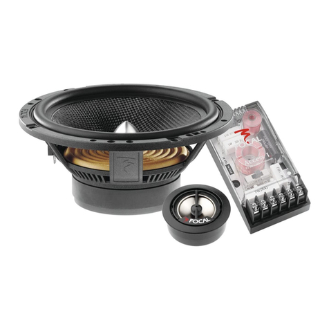
1. Clearwater Two-Way
Loudspeakers (4)
2. Clearwater Headrest Harness
“full”for all years (1)
3. Clearwater Headrest Harness“short”
(1994-97½ 2 Harnesses) (2)
Tools Needed:
1. Phillips Head
Screwdriver (#2)
2. Wire coat hanger
3. Roll of adhesive tape
We are passionate about our audio and you should be too!

Page 3
Installation:
If your Miata did not come equipped with factory headrest loudspeakers,
you will need to install the clearwater Headrest Harness. See Full
Installation 1990-94 or Full Installation 1994-97½.
Installation Time:
There are two levels of installation. If you simply replace your factory
headrest speakers with the Clearwater speakers, installation time
should be approximately 25 minutes. If you need to install the Harness,
installation time should be approximately 1-2 hours for 1990-94 and
approximately 40 min. for 1994-97½. We strongly suggest that you do
the full installation to correct any potential incorrect Mazda factory wiring
mistakes. These were common in early cars…..
Replacement Install:
• Unzip the top of each headrest cover. Fold forward the cover and
remove the perforated white plastic cover. (If zipper is stuck, rub some
sort of lubricant on it to make it easier to unzip, otherwise you could
damage the zipper.)
• Remove the four small Phillips head screws that mount the factory
speakers to the black plastic rectangular speaker frame. Gently pry the
factory speaker from the frame.
• Remove the two slide-on speaker connectors from each speaker.
Remove factory speaker.
• You will need to pull each of the factory speaker wires through the
bottom of the black plastic frame. A rubber grommet surrounds each of
the wires.
• Now remove the three larger Philip screws that attach the black plastic
frame to the seat back. Remove the black plastic frame.
• Position the Clearwater speaker near the headrest and slide-on each
of the factory connectors.
• Gently spread the headrest foam apart and press into place each of
the Clearwater speakers. It is best to push the foam inwards. Screws are
not used to mount the speakers, the foam will hold them in place.
• Position the white perforated plastic cover in place and zip the
headrest cover. Do not pull zipper too hard or you may risk tearing the
zipper.
Step 2: Installation

Page 4
Step 2: Installation
Full Installation:
(For use in Miatas not originally equipped with headrest harness
connectors located under the seat)
Make note of radio code if programmed. (See Miata owner’s manual)
Radio / Console Removal:
• Unscrew gear shift knob. (HINT: On Limited Edition model, remove the
Allen set screw first)
• Proceed to remove 5 screws holding console. Set console aside. (2 in
storage, 1 under ash tray, 2 on each side of console)
• Use a bent coat hanger (in shape of hook) to remove air vent
“eyeballs” located in the center of the dash just above the radio. Loop
coat hanger through center of the eyeball and back out. Hold both ends
of the wire together. Brace the face plate with other hand and pull very
firmly. The eyeballs may require a good amount of force to remove. An
assistant may be helpful.
• Remove center dash face plate by unscrewing all 3 screws. (2 near top
of eye sockets and 1 in lower left corner)
• Gently separate frame from dash only a few inches and then unplug
hazard and head lamp raising switches. Now, completely remove frame.
• Remove 4 screws from radio.
• Gently pull radio out a few inches.
Headrest Harness Routing:
The harness runs from the back of the radio, down the length of the
center console, down under the seats, up the back of the seats, through
the back of the seat foam and out the front of the seat to the speaker
location.
The white rectangular connector end needs to be run between the
plastic frame of the radio console and the carpet. (HINT: It is helpful to
slip the connector under the right side of the frame) Slide the headrest
harness to the left side of the opening. Route harness behind the steel
radio frame to the left interior side of the radio opening.

Page 5
Step 2: Installation
Connections:
• If you have an aftermarket radio, check your owner’s manual for wiring
information. You will need to cut off the white rectangular connector on
the Harness.
• Wiring code is: Red /Right + Black /Right- Green /Left+ Gray /Left-.
• For factory radios, connect the white rectangular connector to back of
the radio. Gently push in until a “click” sound is heard.
• Run the harness the length of the center console.
• Route the Harness the length of the center console to approximately
1 foot from the rear of the console. Separate the harness so that one
half goes down through the holes in the carpet used for the console
mounting screws and out the bottom where the seat belt anchor bolts
are attached. (HINT: Use a coat hanger to guide the wires) It may be
helpful to remove the six plastic pop clips holding down the carpet to the
rear panel to help gain access to the carpet.
Speaker Installation:
• 1994-97½: Locate factory headrest connector under the front of the
seat near the center of the Miata.
• Plug Clearwater Harness into factory connector.
• Refer to the rest of the Installation.
• 1990-97½: Slide each seat forward. Unzip the top of each headrest
cover. Fold forward the cover and remove the perforated white plastic
cover. Fold the top of the seat cover back (as you would fold back the
“hood” of a coat) to expose the foam of the seat.
• Straighten a coat hanger and form a small loop about 3/4” long,
apply tape to the tip to cover any sharp edges. Slide the coat hanger
down from the back of the seat cover from top to the bottom. Attach the
speaker wires to the hanger with tape and gently pull the hanger/wire
assembly up the back of each seat.
• Locate the small round hole in the middle of the back of each seat.
The headrest wires will need to go through the foam towards the upper
front of each seat. Feed the coat hanger (with the wires attached with
tape) through the hole in the seat .Your seat may have a pre-punched
hole going through the seat. This hole goes upward from the back
of the seat up and forward towards the front of the seat. If not, use a
coat hanger or a long screwdriver to route the wires through the seat.
(HINT: It may be helpful to remove the center circular metal staple that
holds the front seat cover below the headrest speaker cavities. This will

Page 6
Step 3: Testing, Re-assembly & Product Specs.
improve access to the hole in the seat.)
• Attach the Red and Black wires to each of the “right” speakers and the
Gray and Green wires to each of the “left” speakers in each seat.
• Gently spread the headrest foam apart and press into place each of
the Clearwater speakers.
• Screws are not used to mount the speakers, the foam will hold them in
place.
• Position the white perforated plastic cover in place and zip the headrest.
• Check all connections.
• Turn down volume on radio.
• Turn ignition key to the Accessory position.
• Check operation of system.
Re-installation of Radio:
• Re-install radio. (HINT: When installing radio, check alignment of rear
support tab on back of radio to hole in metal frame.) Do not forget to
attach the hazard light / headlight raising switch connector!
• Re-install center dash face plate, eyeball vents, console and shift knob.
Wiring Instructions for Non-Factory Radio or Amp:
• Connect the amp left hot (+, green wire) to the hot (+) on the driver’s
left speaker.
• Wire between left driver ground and left passenger hot loops back
toward amp.
• Connect the amp left ground (-, grey wire) to the passenger left ground.
• Connect the amp right hot (+, red wire) to the hot (+) on the driver’s
right speaker.
• Wire between right driver ground and right passenger hot loops back
toward amp.
• Connect the amp right ground (black wire) to the passenger right ground.

Page 7
Step 4: Install on Upgraded Miata Factory Speakers
Removal and Installation:
• Remove 4 screws that hold speaker grill to seat back. (Under Tape)
Refer to image A.
• Remove factory wiring from speakers, remove and replace.
• Install the new Clearwater headrest speakers using only two nubs
instead of four. Shown below in image C.
• Attach wires to new speakers and replace grill into the seats.
A B
C
Wire loops back to amp
between driver and
passenger speakers

Thank you for purchasing your Clearwater Speakers. Please feel free to
send us comments or suggestions at any time. We love to hear from our
customers. If you have the time we would love to see some pictures of you
and your car. Send your photos to us at sales@clearwateraudio.com or
mail them to us at P.O. Box 428, Folsom, CA, 95763.
Sincerely,
Glenn and the team at Clearwater.
The Clearwater Company |2546 Mercantile Dr. Ste B | Rancho Cordova, CA 95742
Phone: (916) 852-7029 |Fax: (916) 852-9410 |www.clearwateraudio.com
Version 6.1 | 10/12/12
Product Specifications:
THD:
Frequency Response:
Impedance / 90-94:
Impedance / 95-97½
Power Handling:
Dimensions:
All specifications subject to change without notice
0.05%
50Hz - 20kHz ± 3dB
6 ohms
6 ohms
35 watts per speaker
3.5”
Table of contents
