Directory
CHAPTER 1 INTRODUCTION ...................................................................................................................1
1.1 PRODUCT OVERVIEW...............................................................................................................................1
1.2 KEY FEATURES ........................................................................................................................................1
1.3 SPECIFICATIONS.......................................................................................................................................2
1.4 PRINCIPLE CHART.................................................................................................................................... 3
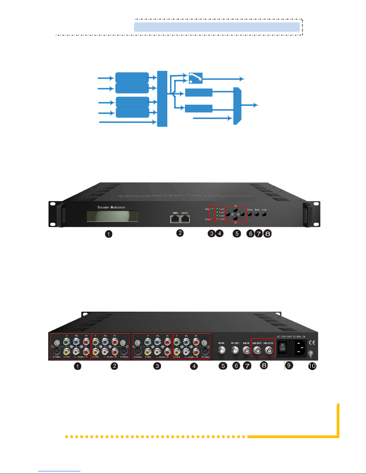
1.5APPEARANCE AND DESCRIPTION ............................................................................................................. 3
CHAPTER 2 INSTALLATION GUIDE...........................................................................................................2
2.1 GENERAL PRECAUTIONS.......................................................................................................................... 2
2.2 POWER PRECAUTIONS.............................................................................................................................. 2
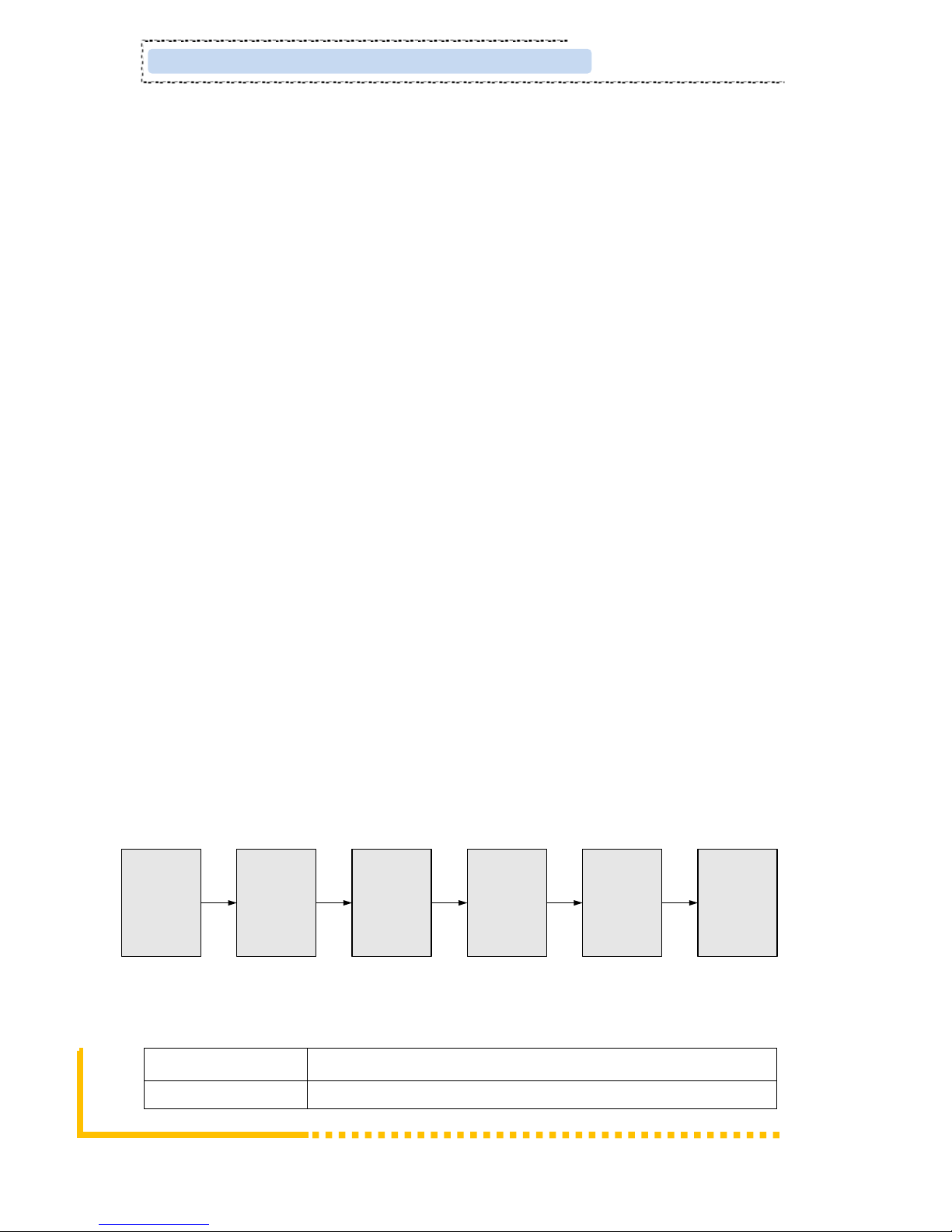
2.3 DEVICE’S INSTALLATION FLOW CHART ILLUSTRATED AS FOLLOWING..................................................... 2
2.4 ENVIRONMENT REQUIREMENT ................................................................................................................2
2.5 GROUNDING REQUIREMENT ....................................................................................................................3
CHAPTER 3 OPERATION..........................................................................................................................4
3.1 LCD MENU STRUCTURE.......................................................................................................................... 4
3.2 INITIAL STATUS........................................................................................................................................5
3.3 GENERAL SETTINGS FOR MAIN MENU..................................................................................................... 6
CHAPTER 4 WEB NMS OPERATION .......................................................................................................14
4.1 LOGIN .................................................................................................................................................... 14
4.2 OPERATION............................................................................................................................................ 15
CHAPTER 5 TROUBLESHOOTING...........................................................................................................25
CHAPTER 6 PACKING LIST .....................................................................................................................26
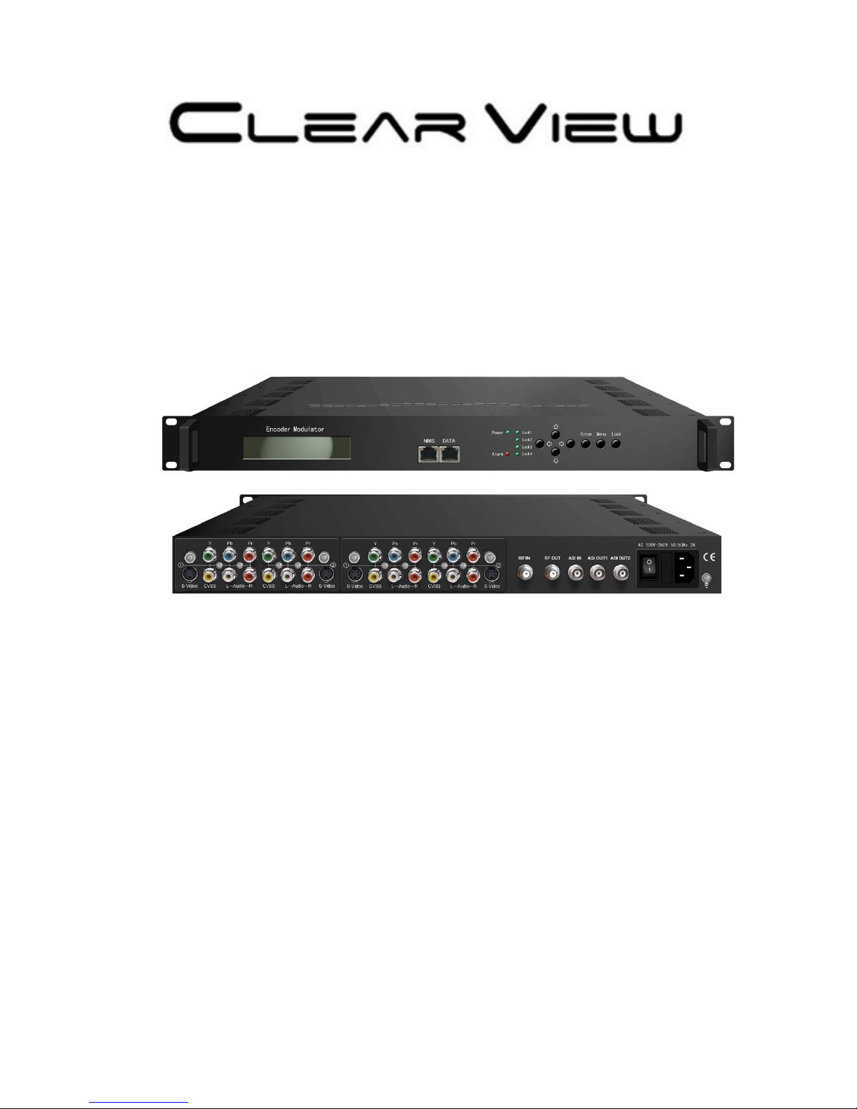
SD4260 S-Video/CVBS/YPbPr to DVB-T Encoder Modulator User Manual