Clemco Spin - XL User manual

Revision 03
O W N E R’ S M A N U A L
Spin - XL
with pneumatic driven
blast-head
24407D
Clemco
International GmbH Carl-Zeiss-Straße 21 Tel.: +49 (0)8062 – 9008-0
Germany Web: www.clemco-international.com

Page 2 of 15
INDEX
1 SHORTCUTS, DEFINITIONS, SYMBOLS AND ICONS ....................................... 3
2 PRODUCT DESCRIPTION ................................................................................... 4
2.1 CONVENTIONAL UTILIZATION AND RESTRICTIONS ............................................................................ 4
2.2 NO CONVENTIONAL UTILISATION – WARNINGS FOR MISUSE ............................................................. 4
2.3 OPERATING MODE OF COMPLETE SYSTEM ...................................................................................... 4
2.4 DESCRIPTION ............................................................................................................................... 4
2.4.1 Complete system ................................................................................................................ 4
2.4.2 Operating elements ............................................................................................................ 5
2.5 ENERGY CONSUMPTION ................................................................................................................ 5
2.6 EMISSIONS ................................................................................................................................... 5
3 SET-UP AND OPERATION .................................................................................. 6
3.1 TRANSPORT ................................................................................................................................. 6
3.2 UNPACKING AND DISPOSE OF PACKING MATERIAL ........................................................................... 6
3.2.1 Elimination, recycling, disposal of equipment ..................................................................... 6
3.3 STORAGE ..................................................................................................................................... 6
3.4 SET-UP FOR INITIAL INSTALLATION / OPERATION ............................................................................. 6
4 INSTRUCTION HANDBOOK ................................................................................ 7
4.1 OPERATION .................................................................................................................................. 7
4.1.1 Standard operation ............................................................................................................. 7
4.1.2 Shutdown ............................................................................................................................ 7
5 MAINTENANCE AND CLEANSE ......................................................................... 7
5.1 GENERAL ..................................................................................................................................... 7
5.2 MAINTENANCE CYCLES ................................................................................................................. 8
5.3 AFTER OTHER PERIODS OF TIME .................................................................................................... 8
6 TROUBLESHOOTING .......................................................................................... 8
7 ADMITTED MODIFICATIONS FOR USERS ......................................................... 8
8 REPLACEMENT PARTS ...................................................................................... 9
9 SUMMARY, REST HAZARD AND SAFETY PRECAUTIONS ............................ 11
9.1 NOISE POLLUTION .......................................................................................................................11
9.2 DUST POLLUTION ........................................................................................................................11
9.3 ESCAPE OF SPED BLAST MEDIA OF WEAR PARTS ...........................................................................11
10 APPENDIXES .................................................................................................. 12
10.1 MANUAL FOR AIR MOTOR TYPE MRD, STALL-PROOF, OIL FREE ..................................................12

Page 3 of 15
1 Shortcuts, definitions, symbols and icons
Whipping
hose
Interlock coupling.
Ele
c
trostati
c
strokes
.
Ground!
Noise > 85dB(A)!
Wear ear protection.
Explosi
on hazard caused by
dust!
Ground!
Explosion hazard!
Connect only max. admitted
pressure.
Risk of injury!
Discharge completely pressure
during maintenance jobs.
Recycling
Garbage
Change within
Europ
e
Complete blast protective
clothing.
Whipping hose!
Hold tight end of hose.
X(m)= 10 x P(bar)
X
Dangerous area!
Without protective clothing keep
out of area of 10x of pressure.
Used pictograms
Risk of escaping blast media.
Mortal danger!
Wear blast helmet, protective clothing, cloves
Risk of whipping hose and escaping blast
media.
Mortal danger!
Interlock coupling.

Page 4 of 15
2 Product description
2.1 Conventional utilization and restrictions
Parts to be blasted
- Inside of pipes
- Inside of cylindrical parts
Operating conditions
- indoor or outdoor
- acceptable temperature: -5° ... 40°C
- acceptable humidity: 0 ... < 100% (no rain!)
Compressed Air
- pressure: 6 to 8bar
- pressure air category 4, DIN ISO 8573
- air volume: see table 1
- air service unit for air motor:
max. part size: 15μm
max. part density: 8mg/m³
dry air: water content max. 6g/m³
oil free!
Acceptable medias/ abrasives
- mineral and metallic blast media
- acceptable size see table 1
- dry and pourable
- use of Aluminium Oxide and Silicium Carbid causes high wear
Suggestion for parameters
see table 1
Table 1:
for inner
diameter
(mm)
no
zzle
-
Ø
Size of blast media (µ)
Min. air volume
(m³/min)
400 - 700
8,0
400-800 10,0 (353 CFM)
700 - 1500
9,5
(400) 800-1200 15,0 (530 CFM)
2.2 No conventional utilisation – Warnings for misuse
Utilization is interdicted:
- in explosion hazard zones
- for blasting parts, where hazardous materials were released
o by explosion hazards
o which causes damages caused to somebody's health during a defective dust collector
2.3 Operating mode of complete system
- place Spin XL at the end of the pipe
- switch on system
- air motor turns blast head
- air-blast media mixture escapes radial
- pull back equipment manually: inner surface of pipe gets blasted/ cleaned
- blastmedia-dust mixture gets exhausted at end of pipe (option)
2.4 Description
2.4.1 Complete system
To get the CE-conformance Clemco recommends the following components/ activities:

Page 5 of 15
- Blast pot with
+ Remote control RMS 2000
+ Separate control of:
* Air for blasting
* Air for air motor
* Media metering
+ Diameter of hose or lance: 32 ... 38mm, length max. 20m
+ Pneumatic metering valve (e.g. PT)
- Spin-XL with carriage
- Air service unit for air motor, oil free!, (use included filter/ air service unit) with air hose (inner diam-
eter: min. 9mm, length max. 20m) for air supply
- Safety precautions for blast media emission, dust and noise exposure
Further description is based on above mentioned equipment configuration.
2.4.2 Operating elements
W
here
Comment/ Func
tion
Pressure regulation of
air motor
Air service unit at blast
pot
3 …
6
… max. 7bar
ON/ OFF at remote control handle
Pressure regulation of
blast nozzle
Blast pot 4 - 7bar
ON/ OFF with slide valve at remote control handle
Metering media Metering valve at pot ON/ OFF with slide valve at remote control handle
ON / OFF Remote control handle Activating:
air motor
blast air
metering blast media
2.4.3 Air service unit for air motor
Mount included air service unit for air motor and con-
nect it in vertical position with air supply.
Use green air hose to connect outlet with air motor.
2.5 Energy consumption
Pressure air consumption:
- nozzle see 2.1 table 1
- air motor: 5,6l/s at 6bar operating pressure
2.6 Emissions
- Noise: > 80dB(A)
- Dust: in unacceptable high concentration sanctions such as housing and aspiration

Page 6 of 15
3 Set-up and operation
3.1 Transport
Weight app. 40kg
Protect from beats Observe instruction of complete system
3.2 Unpacking and dispose of packing material
Recycling
Garbage
Change within Europe
3.2.1 Elimination, recycling, disposal of equipment
Disassemble equipment and
separate for materials
3.3 Storage
Storage in dry area Observe instruction of complete system
3.4 Set-up for initial installation/ operation
A1 Adjust carriage to pipe diameter See also chapter 8, table 2.
Risk of whipping hose!
Mortal danger!
Interlock coupling.
A2 Connect Spin XL with blast hose and pot.
Connection for
exhaust air
supply air
A3 Connect air motor with green air hose and
upstream air service unit.
A4 Position Spin XL in pipe.
A5 Function test without blast media.
A6 Set air motor under pressure. Blast head turns.
A7 Adjust pressure of air motor (6bar at mo-
tor app. 90min-1)
max. 7bar
a
t
m
otor
(attend pressure drop
of long hoses!)
A8 Activate blast pot. Air comes out at nozzle.
A9 Function test with blast media.
Risk of escaping blast media.
Mortal danger!
Wear blast helmet, protective clothing,
gloves.

Page 7 of 15
X(m)= 10 x P(bar)
X
Dangerous area!
Without protective clothing keep out of
area of 10x of pressure.
A6-8 Activate air motor and blast pot.
A10 Open metering valve. Air and blast media mixture comes out at
nozzle
A11 Adjust blast media at metering valve. Blast media should only be visible as a
fine fog!
4 Instruction handbook
4.1 Operation
4.1.1 Standard operation
A1 Protect workplace. - Dust emission
- Noise
- Sped up blast media
X(m)= 10 x P(bar)
X
Dangerous area!
Without protective clothing keep out of
area of 10x of pressure.
Risk of escaping blast media.
Mortal danger!
Wear blast helmet, protective clothing,
cloves
A2 Position Spin-XL.
A3 Switch on. First air of air motor
Than air of blast pot
At last blast media.
A4 Pull back Spin XL. According to request of degree of purifica-
tion.
A5 Switch off. First blast media
Than air of blast pot
At last air motor.
4.1.2 Shutdown
4.1.2.1 After end of work
No special activity. Observe instruction of complete system
4.1.2.2 Shut down by longer interruption of work or moving equipment
No special activity. Observe instruction of complete system
5 Maintenance and cleanse
5.1 General
Blast equipment subjects to strong wear. Safety and high efficiency is only ensured
when maintained regularly!
Maintenance cycles are strongly regulated by operating parameters. Stated times are experiences, that
have to be reduced or extended in individual case.

Page 8 of 15
5.2 Maintenance cycles
Maintenance
cycles for
steel shot
(working
hours)
Risk of wear!
Demolition of equipment.
max. 8h Nozzles and blast head. Check and replace if necessary sealing of
nozzles and blast head.
max. 16h Plastic sealing. Check and replace if necessary.
Carbide insert head. Check and replace if necessary.
Shaft and felt seal. Check and replace if necessary.
Shaft seal position: open side to back!
max. 30h Ball bearings. Check and replace if necessary.
max. 50h Moisture separator. Clean only with soap and warm water.
Air and blast hoses. Gaskets of couplings for wear. Blast hose
by hand for soft spots.
Blast pot. Pop up valve for wear by hand.
max. 300h Air motor. Maintenance by Clemco or service man of
producer.
5.3 After other periods of time
Arti
c
l
e
replace (even without wear) after maximal
Blast hoses 6 years
Remote control hoses 6 years
Air hoses – external air supply 6 years
O-rings 5 years
Pop up valve (blast pot) 5 years
Gaskets 5 years
6 Troubleshooting
Problem
Probable cause
Remedy
Blast head
does not turn or
too slowly
1. Volume or pressure of air at motor is
too less.
Increase volume/ pressure of air for air
motor.
2 Leakage/ bend in supply hose of air
motor.
Replace or place straight.
3. Width/ length of supply hose unsuitable.
Width of hose 6mm: max. 10m
Width of hose 9mm: max. 20m
4. Entered dust interlocks axle. Felt seal/ shaft seal/ ball bearing wear
replace
Irregular blast
result.
1. Pulsing blast media. Reduce metering.
2. Moist blast media. Replace blast media with dry one.
Vibrations. 1. One nozzle blocked. Eliminate blockage.
2. Different sizes of nozzles. Use equal nozzles (length and diameter).
3. Fixture wheels loose. Tighten screws.
7 Admitted modifications for users
Only with the improvement of the producer! Otherwise the installation will loose guarantee and CE-
certification

Page 9 of 15
8 Replacement parts
46
9
45
1
5
4
2
3
13
7
8
6
10
19
11
12
22
47
1
33
14
15
30
16
17
18
20
9
21
23
16
27
28
29
31
32
41
18
26
25
40
38
22
37
36
35
39
42
43
44
34
24

Page 10 of 15
Nr
.
Art.
-
Nr.
Bezeichnung
Description
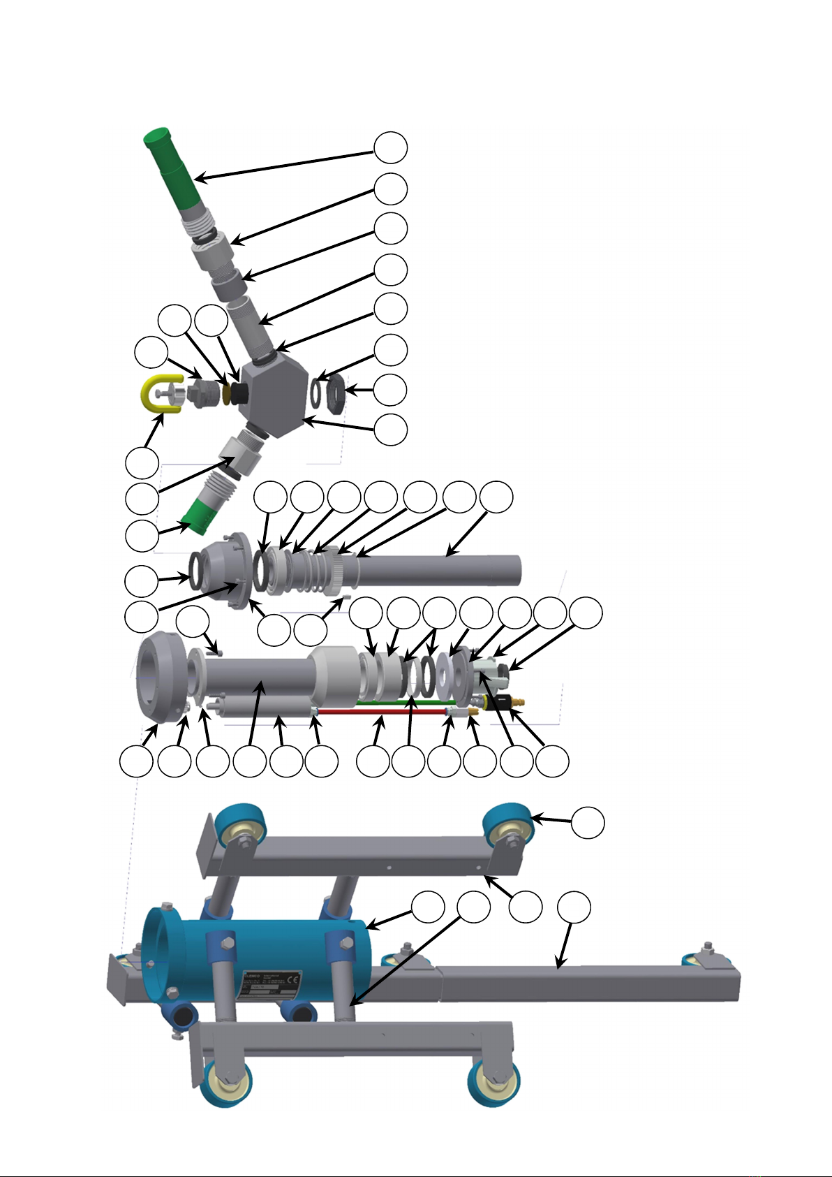
24407D Basis Rohrinnenstrahlgerät Spin XL mit
pneumatisch angetriebenem Strahlkopf,
inkl. Spin XL Fahrgestell 400-580 (Art.
24443D), Filterregler und 10m Luft-
schlauch.
Spin XL basic with pneumatic driven blast
head, incl. Spin XL carriage 400-580 (part
24443D), filter regulator and 10m air
hose.
1 24439D Halterung Räder Fixture wheels
2 24440D Gestell Räder (ohne PU-Rollen) Frame wheels (without PU-wheels)
3 24445D Rohr 1" - 160mm (in "Fahrgestell 400-
580")
Rod 1" - 160mm (in carriage 400-580
incl.)
24449D Rohr 1" - 275mm (in "Fahrgestell 580-
800")
Rod 1" - 275mm (in carriage 580-800
incl.)
24452D Rohr 1" - 635mm (in "Fahrgestell 790-
1500")
Rod 1" - 635mm (in carriage 790-1500
incl.)
24446D Kappe Cap
4 24441D PU-Rolle D80 PU-wheel D80
5 24453D Gestellverlängerung (ohne Rad) empfoh-
len für Ø > 800mm (enthalten in Fahrge-
stell 790-1500)
Frame extension (without wheel) recom-
mended for Ø > 800mm (in carriage 790-
1500 incl.)
6 27192D DL-Motor, abwürgefest + ölfrei Air motor, stall-proof + oil free
7 24435D Stirnzahnrad Z20 Gear wheel Z20
8 90592D Madenschraube M4x6 Headless screw M4x6
9 24433D Elsa gerade 8-1/8 A Elsa straight 8-1/8 A
10 27224D PA-Schlauch 8/6 rot, pro Meter - 0,25m PA-hose 8/6 red, per meter - 0,25m
27225D PA-Schlauch 8/6 grün, pro Meter - 0,25m PA-hose 8/6 green, per meter - 0,25m
11 24434D Elsa gerade 8-1/4 A Elsa straight 8-1/4 A
12 27198D Schalldämpfer 1/4" Exhaust silencer 1/4"
13 24428D Deckel Antrieb Cap
14 24413D Mantelrohr Casing tube
15 90155D Zylinderkopfschraube M6x18 Hexagon bolt M6x18
16 24414D Kugellager Ball bearing
17 24415D Mantelrohr Einsatz Casing tube insert
18 24417D Wellendichtring 50x68x8 Shaft seal50x68x8
19 24416D Mantelrohr Distanzring Casing tube distance ring
20 24430D Dichtung Kunststoff Sealing plastic
21 24429D Anschlussflansch Connecting flange
22 24431D Zylinderkopfschraube M5x16 Hexagon bolt M5x16
23 24232D CFT-Kupplung 1 1/2" CFT-Coupling 1 1/2"
24 08416D Dichtung CQG 32 Sealing CQG 32
25 24426D Kopf Antrieb Head
26 24427D Filzdichtung 6x6-177 Felt seal 6x6-177
27 24424D Hülse Feder Bushing spring
28 24425D Druckfeder Spring
29 24421D Stirnzahnrad Z80 Gear wheel Z80
30 24420D Paßfeder 6x6x14 Flat key 6x6x14
31 24419D Sicherungsring 50x2 Snap ring 50x2
32 24418D Welle Axle
33 24412D Dichtung Kopf Eingang PU Sealing head entrance PU
34 24408D Strahlkopf Blast head
35 24409D HM-Einsatz Kopf Hardened insert head
36 24410D Dichtung Kopf PU Sealing head PU
37 24411D Blindstopfen 1 1/4" mit M8 Blank plug 1 1/4" with M8
38 100956 Anschlagpunkt Attachment point
39 91025D Düsendichtung NW32 Sealing blast nozzle NW32
91023D Düsendichtung NW25 Sealing blast nozzle NW32
40 24444D Düsenhalter 25 Nozzle holder 25
41 *) Kurzdüse mit NW25 Short nozzle with NW25
42 90437D Rohr 1 1/4" - 95 (in "Fahrgestell 790-
1500")
Tube 1 1/4" -95mm (in carriage 790-1500
incl.)
90435D Rohr 1 1/4" - 285 (in "Fahrgestell 790-
1500")
Tube 1 1/4" -285mm (in carriage 790-1500
incl.)
43 24451D Muffe 1 1/4" (in "Fahrgestell 790-1500") Pipe coupling 1 1/4" (in carriage 790-1500

Page 11 of 15
incl.)
44 24448D Düsenhalter 32 (in "Fahrgestell 790-
1500")
Nozzle holder 32 (in carriage 790-1500
incl.)
45 *) Strahldüse mit NW32 Blast nozzle with NW32
46 27194D Kontermutter 1 ½“ Lock nut 1 ½”
47 27200D Vorfilter DL-Motor Prefilter air motor
24438D Filterregler 5µm, G1/4" für DL-Motor Filter regulator 5µm, G1/4" for air motor
90381D Luftschlauch 9mm x 10m, inkl. Kupplun-
gen
Air hose 9mm x 10m, incl. couplings
90073D Luftschlauch 9mm x 20m, inkl. Kupplun-
gen
Air hose 9mm x 20m, incl. couplings
*) Auswahl Strahldüsen siehe Preisliste oder fragen Sie Ihren Händler. Range of blast nozzles see price list or ask your
distributor.
Tabelle 2
Inner diameter of pipe
[mm]
Extension no
z-
zles
Kind
of nozzle
Length of rod
for frame [mm]
Spin XL
carriage
…
400 … 580 (15,5" - 23")
/ Short nozzle with
NW25
160
400
-
580
(24443D)
Spin XL carriage
extensions
580 … 800 (22,5“-
31,5“)
/ Long nozzle with
NW32
275
580
-
800
(24447D)
790 ... 1200 (31“ - 47“) 95mm (90437D) Long nozzle with
NW32
635
790
-
1500
(24450D)
1200 ... 1500 (47“ - 59“)
285mm (90435D)
Long nozzle with
NW32
635
790
-
1500
(24450D)
9 Summary, rest hazard and safety precautions
9.1 Noise pollution
Noise levels > 80dB(A) can occur use ear protection.
9.2 Dust pollution
Adequate methods have to be chosen to meet the acceptable contamination.
9.3 Escape of sped blast media of wear parts
Blasting subjects to strong wear that can cause hazards. Therefore the required mainte-
nance cycles of chapter 5 have to be followed exactly!
Especially the blast hose has to be checked to reduce existing hazard.

Page 12 of 15
10 Appendixes
10.1 Manual for air motor type MRD, stall-proof, oil free

Page 13 of 15

Page 14 of 15

Page 15 of 15
Table of contents