manuals.online logo
Brands
  1. Home
  2. •
  3. Brands
  4. •
  5. Martin-Till
  6. •
  7. Ultrasonic Jewelry Cleaner
  8. •
  9. Martin-Till BD1345 User manual

Martin-Till BD1345 User manual

1345 ROW CLEANER
INSTALLATION INSTRUCTIONS
Martin Industries LLC
206 Elk Fork Road
Elkton, KY 42220
Telephone: 270-265-5817
E-Mail: martin@martintill.com
www.martintill.com VERSION 01/30/2019
SHOWN WITH BD MOUNT AND OPTIONAL SMARTCLEAN CYLINDER
AND BRACKETS, RAZOR WHEEL(RTW1412.5) , SIDE TREADER WHEELS
(
STW-04 )
& CAM ADJUST
(CA03-D)
BD
BK
BCIH
STEP 1 : ATTACH THE MOUNT TO THE PLANTER
If you purchased the optional SmartClean System, Install the SmartClean cylinder top brackets on the mount (as shown
in the picture) before attaching the mount to the planter. You have received 1/4” longer bolts in this case.
Using four 1/2” X 1 1/2 ” bolts, attach the mount to the planter face plate, and torque mounting nuts to 57 ft-lbs.
Some of the SmartClean bracket sets are shown below . Use the instructions in Step 4 to install the bottom brackets.
1
SC-BKW1345 SC-BD1345
Attach the Right and Left L shape brackets ( CIH1360R & CIH1360L) to the planter using provided
two 1/2” X 3 1/2” Grade 8 bolts and nuts as shown in the right picture. Torque to 80 ft-lbs. Using
four 1/2” X 1 1/2 “ bolts, attach the mount to the L shape brackets, and torque mounting nuts to 57
ft-lbs.
FOR CASEIH 1200 SERIES PLANTERS (BCIH 1360)
2
CIH1360R
CIH1360L
STEP 2: ATTACH 1360 FRAME ASSEMBLY TO THE MOUNT
1. Place the bushings (BU7858) inside the frame’s arms pin point holes.
2. Align the holes in the mount and the frame assembly. Insert the 5/8” x 2” bolts and washers ( you have
not received washers if you are provided with flange bolts instead of HEX bolts ) from the outside and
place nuts on the 5/8” x 2” bolts from inside.
3. Tighten the bolts to 112 ft-lbs. Check after first day of use.
4. Check to ensure the frame is not binding on the mounting bracket and is free to float up and down.
5/8” X 2” FLANGE BOLT
(BFS0152)
BUSHING (BU7858)
FLANGE NUT (NFSL007)
SHOWN WITH MT1345DS MOUNT
STEP 3 : INSTALL THREADED ADJUSTMENT ASSEMBLY
1. Place the adjustment assembly against the frame as shown in diagram below.
2. Secure the adjustment assembly to the frame using the three button head screws and nuts provided.
3. Put the 1/2” nut on the 1/2” x 4” bolt and thread the bolt into the tapped hole of the adjustment
assembly. Use the 1/2” nut to lock the 4” adjustment bolt in place once the desired minimum depth set-
ting has been determined.
3
3/8” x 1 1/4” BUTTON HEAD ALLEN
3/8”-16 FLANGE NUT
SB-02 STOP BLOCK
1/2” -13 X 4” BOLT
1/2” -13 JAM NUT
NOTE: IF USING THE CAM ADJUSTER OPTION SKIP THIS STEP
AND PROCEED TO STEP 4
STEP 4 : INSTALL OPTIONAL CAM ADJUSTMENT ASSEMBLY
1. Mount the cam block to the frame using the three 3/8” buon head bolts.
2. Slide the 1/2” x 4” bolt through the knob, spring, and support block and thread it into the cam.
3. Tighten the bolt unl the cam is directly adjacent the support block but sll loose enough to be disengaged from
the pin by pushing on the knob.
4. Install the 1/2” nut on the end of the bolt and ghten securely against the cam. Torque to 57 -lbs.
4
1/2” X 3 1/2” BOLT
(BSM12NC312)
KNOB (CA-32)
3/8” X 1”BUTTON HEAD
(B5B381)
CAM BLOCK
(CA-31-1345R/L)
(RH SHOWN)
CAM
(CA30) 1/2” FLANGE
NUT (N12CFL)
SPRING
(CA-34)
OPTION B: OFFSET
(Left wheel in front hole and right wheel in rear hole)
The staggered configuration allows the wheels to turn more easily in loose soil.
With this configuration, we suggest running the left wheels in the rear hole on the half of the plant-
er and the right wheels in the rear hole on the other half of the planter (when viewed from behind).
STEP 5 : DETERMINE THE BEST WHEEL CONFIGURATION FOR
YOUR SOIL CONDITIONS
OPTION A: INTERSECTED
(Both wheels in front hole)
Both wheels forward provides maximum cleaning effect. The interlocked wheels till the middle of
the seed row.
5
6
STEP 6: INSTALL WHEEL ASSEMBLIES
1) Secure the hub to the frame with the 5/8” X 3” flange bolt, washer and nut. Using a torque-
wrench, tighten to 116 ft-lbs. Install the dust cap.
2) Install the wheel (part # to the outside) and side treader wheel on the hub, using the four car-
riage bolts and flange nuts. Torque to 23 ft-lbs. Re-tighten after first day’s use.
3) The wheel marked TW3813-L4 is for use on the left side of the frame (as viewed from behind the
machine). Repeat for opposite side.
3/8” FLANGE
NUTS
(NSFL003)
DUST CAP
(HS1328)
5/8” X 3
FLANGE BOLT
(BFS0156)
OPTIONAL SIDE TREADER
WHEEL
(STE-04A)
WHEEL (LEFT)
(OPTIONAL RTW1412.5L4 SHOWN)
HUB
(CHU44-B2)
BEARING RETAINER
(BC-01)
WASHER
(WSN0064)
FLANGE NUT
(NFSL0007)
BEARING
(5203KMF)
7
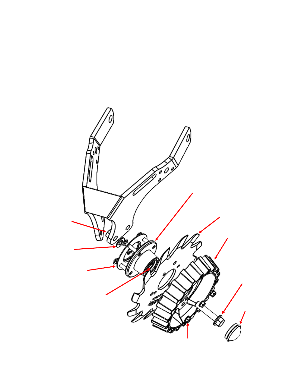
STEP 7: INSTALL OPTIONAL DEFLECTOR (SCRAPER)
NOTE: The Deflector (Scraper) is recommended when operating in wetter conditions, or damp
stringy residue, to reduce wrapping.
NOTE: The Deflector (Scraper) comes in pair of left and right for left and right wheels.
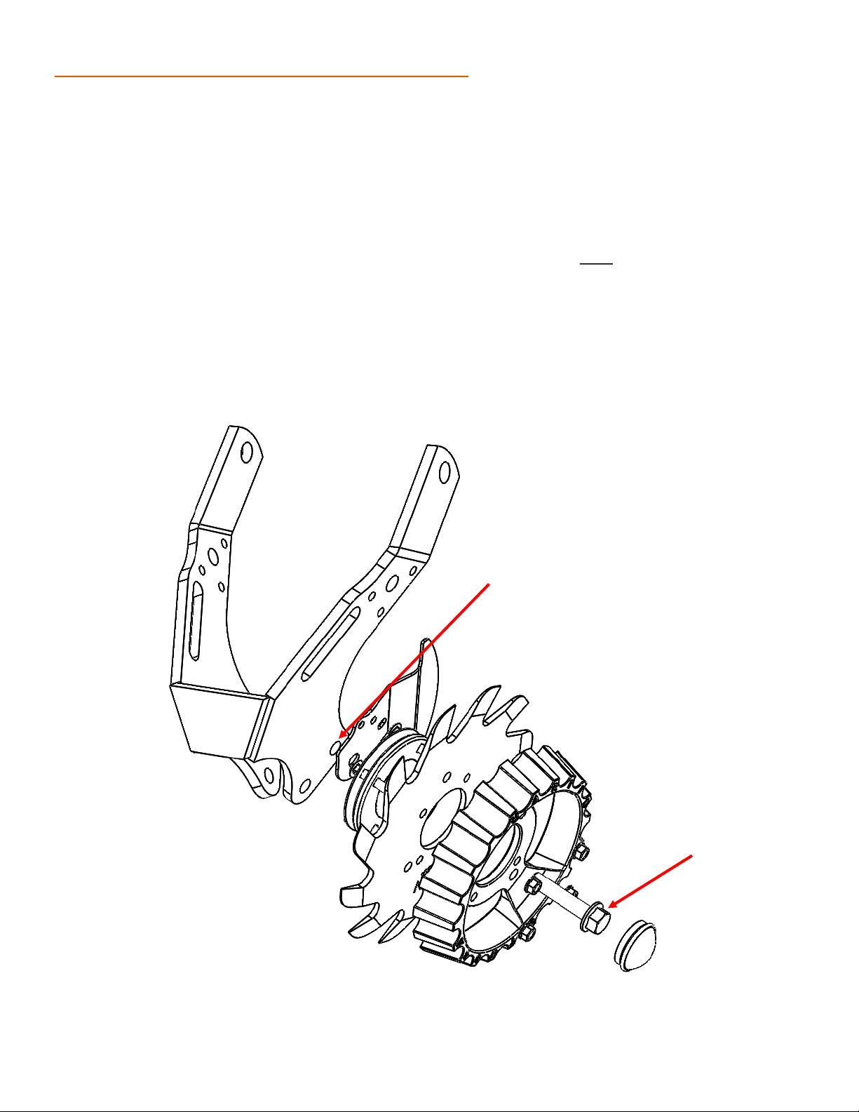
Intersected Configuration ( Wheel in front hole)
1) Place the deflector (Scraper) on the back of the assembled wheel unit (previously assembled in
step 6) as shown here and pass the flange bolt (BFS0156) through the wheel assembly and the
deflector and attach the flange nut (NFSL007) hand tighten and locate the deflector as shown
and torque the flange bolt (BFS0156) to 116 ft-lbs being careful not to allow the deflector to ro-
tate during bolt tightening.
2) The wheel marked TW3813-L4 (Or RTW1412.5-L4 for the Razor wheel) is for use on the left side
of the frame (as viewed from behind the machine). Repeat for opposite side.
NOTE: When the deflector (scraper) is to be installed the washer (WSN0064) is NOT used
FLANGE NUT
(NFSL007)
FLANGE BOLT
(BFS0156)
DEFLECTOR
(SCRAPER)
(ITD STW L)
(SHOWN IN CORRECT
POSITION)
8
Offset Configuration ( Wheel in rear hole)
1) Place the deflector (scraper)on the back of the assembled wheel unit (previously assembled in
step 6) as shown here and pass the flange bolt (BFS0156) through the wheel assembly and the
deflector using the rear hole in the frame unit and attach the flange nut (NFSL007) hand tighten
and locate the deflector (scraper) as shown and torque the flange bolt (BFS0156) to 116 ft-lbs
being careful not to allow the deflector to rotate during bolt tightening.
2) The wheel marked TW3813-L4 (Or RTW1412.5-L4 for the Razor wheel) is for use on the left side
of the frame (as viewed from behind the machine). Repeat for opposite side.
NOTE: When the deflector (scraper) is used the washer (WSN0064) is NOT used
FLANGE BOLT
(BFS0156
REAR HOLE
FLANGE NUT
((NFSL007) NOT
SHOWN)
9
STEP 7 : INSTALL THE OPTIONAL SMARTCLEAN CYLINDER
Install the SmartClean cylinder between the top and bottom brackets. Use thicker (7/16 ” ) Pin on
the top brackets and thinner (3/8”) pin on the bottom bracket as shown in the picture below.
NOTE: Cylinder may be installed with elbow valves in either up or down orientation, depending on
user preference.
Note:
It is very important to limit the row cleaner down travel by threaded or cam adjustment assem-
bly to prevent the air cylinder from extending fully by setting stop bolt or cam to catch the row
cleaner just before the cylinder reaches the end of its stroke. Failure to do so will destroy the
cylinder prematurely.
Smartclean Cylinder
(SC-CYL-2X2)
3/8” PIN AND COTTER
PIN (SC-LP38)
7/16” PIN and COTTER
PIN ( SC-TP716)
10
PARTS LIST FOR 1345 HUB ASSEMBLY (CHU44-B2)
BEARING
(5203KMF)
BEARING RETAINER (BC-01)
DUST CAP (HS1328)
HUB (HU44-B2)
Martin Industries LLC
206 Elk Fork Road
Elkton, KY 42220
Telephone: 270-265-5817
E-Mail: martin@martintill.com
The most trusted name in no-till
Established 1991

This manual suits for next models

2

Other Martin-Till Ultrasonic Jewelry Cleaner manuals

Martin-Till UMO-WA1345 User manual

Martin-Till

Martin-Till UMO-WA1345 User manual

Martin-Till DUAL UMO-1360 User manual

Martin-Till

Martin-Till DUAL UMO-1360 User manual

Martin-Till UMO-WA1360 User manual

Martin-Till

Martin-Till UMO-WA1360 User manual

Popular Ultrasonic Jewelry Cleaner manuals by other brands

IRIS IC-FDC1U user manual

IRIS

IRIS IC-FDC1U user manual

Lakeland 24191 Instruction booklet

Lakeland

Lakeland 24191 Instruction booklet

Bissell CROSSWAVE HYDROSTEAM 3515 Series instructions

Bissell

Bissell CROSSWAVE HYDROSTEAM 3515 Series instructions

PIE Tergeo-EM Operator's manual

PIE

PIE Tergeo-EM Operator's manual

Kärcher OC 3 operating instructions

Kärcher

Kärcher OC 3 operating instructions

Makita LC09 instruction manual

Makita

Makita LC09 instruction manual

Tower Hobbies CW20 Safety and instruction manual

Tower Hobbies

Tower Hobbies CW20 Safety and instruction manual

Makita DCL180SY instruction manual

Makita

Makita DCL180SY instruction manual

SciCan StatClean user manual

SciCan

SciCan StatClean user manual

GREENFROM SU-768 user manual

GREENFROM

GREENFROM SU-768 user manual

Bobot WIN SPIDER user manual

Bobot

Bobot WIN SPIDER user manual

Kogan KACLUSJW42T user guide

Kogan

Kogan KACLUSJW42T user guide

Mosmatic FL-CR 750 Assembly & instruction manual

Mosmatic

Mosmatic FL-CR 750 Assembly & instruction manual

James ULTRA 7000S user guide

James

James ULTRA 7000S user guide

Makita DCL181F instruction manual

Makita

Makita DCL181F instruction manual

Bissell 2005 SERIES user guide

Bissell

Bissell 2005 SERIES user guide

GreenWorks PWG401 Operator's manual

GreenWorks

GreenWorks PWG401 Operator's manual

DURASONIC DS3L user manual

DURASONIC

DURASONIC DS3L user manual

manuals.online logo
manuals.online logoBrands
  • About & Mission
  • Contact us
  • Privacy Policy
  • Terms and Conditions

Copyright 2025 Manuals.Online. All Rights Reserved.