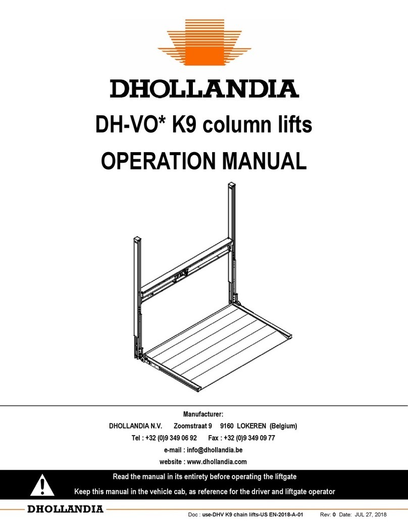
Clemens Technologies S-2R User manual

S-2R + Frontanbau 11.2018 en 1
Operating instructions
Column lifter S-2R for
front and mid mounting
Item no: CG866.300000
CLEMENS GmbH & Co. KG
Maschinenfabrik
Rudolf-Diesel-Straße 8
D-54516 Wittlich / Germany

S-2R + Frontanbau 11.2018 en 2
Contents
Page
1Foreword................................................................................................................................3
2EC Declaration of Conformity ..............................................................................................4
3Introduction...........................................................................................................................5
3.1 General description and purpose of the device................................................................5
3.2 Validity.............................................................................................................................6
3.3 Contact............................................................................................................................6
3.4 General technical data.....................................................................................................6
3.4.1 Machine number ......................................................................................................................6
3.4.2 Required equipment of the tractor ...........................................................................................7
3.4.3 Attachment points to frames made by CLEMENS:..................................................................7
3.4.4 Technical data..........................................................................................................................7
4Safety instructions................................................................................................................7
4.1 General ...........................................................................................................................7
4.2 Attached devices.............................................................................................................8
4.3 Road and transport journey.............................................................................................9
4.4 Maintenance and repair...................................................................................................9
4.5 Noise Information ............................................................................................................9
4.6 Hydraulic system, lubricants..........................................................................................10
4.7 Warning pictographs, nameplate...................................................................................11
5First installation ..................................................................................................................12
5.1 Attachment of the column lifter on the tractor.................................................................12
5.2 Mounting of attachments to the column lifter..................................................................14
6Putting into operation.........................................................................................................14
6.1 Road and transport journey...........................................................................................15
6.2 Operation and adjustment of the machine.....................................................................15
6.3 Removal from the tractor...............................................................................................15
7Maintenance and replacement of wearing parts............................................................... 15
8Storage................................................................................................................................. 17
8.1 Before the season.........................................................................................................17
8.2 After the season............................................................................................................17
9Possible faults and their elimination ................................................................................. 17
9.1 Faults ............................................................................................................................18
9.2 Tightening torques.........................................................................................................18
10 Spare parts list.................................................................................................................... 19
10.1 Three-point frame for front mounting.............................................................................19
10.2 Link arms.......................................................................................................................20
10.3 Adapters and brackets for front mounting......................................................................21
10.4 Accessories for mid-mounting .......................................................................................21
10.5 Column lifter S-2R.........................................................................................................22
10.6 Hydraulic cylinder..........................................................................................................24
10.7 Optional: Steel support wheel for mid mounting.............................................................25
10.8 Optional: Pneumatic support wheel for mid mounting....................................................26
11 List of illustrations.............................................................................................................. 28

S-2R + Frontanbau 11.2018 en 3
1 Foreword
Dear user!
With these operating instructions, you will receive valuable help for the safe and effective
use of your CLEMENS machine. We ask you to read these operating instructions
conscientiously before putting the device into operation andto observe the listed information
and instructions!
Please note that the operating instructions are an integral part of your machine and must be
accessible to the operator at all times. Compliance with the appropriate maintenance
instructions, information on resources and original spare parts help your machine
performance, reliable operation and a long service life. General safety instructions, health
protection requirements and traffic regulations serve your safety and the safety of third
parties and must be followed!
In the course of further technical development, CLEMENS GmbH & Co. KG is constantly
working to improve its products. We therefore reserve the right to make design changes and
changes to the illustrations and descriptions of these operating instructions. Technical data,
dimensions and weights are not binding. Errors excepted.
We thank you for your trust in us and we are sure that you will be satisfied with the
performance and reliability of your machine by following the instructions.
Your CLEMENS GmbH & Co. KG
Note:
The manufacturer is not liable for non-compliance with the operating instructions or when
using non-approved spare parts.
Furthermore, no modifications, attachments or conversions that could affect safety should
be made on the machine without the manufacturer's approval.
© 2017 CLEMENS GmbH & Co. KG
All rights reserved

S-2R + Frontanbau 11.2018 en 4
2 EC Declaration of Conformity
in accordance with EC Directive Machines 2006/42/EC
Manufacturer / Address: CLEMENS GmbH & Co. KG/Maschinenfabrik
Rudolf-Diesel-Straße 8
D-54516 Wittlich/Germany
We herewith declare that the mechanical design of the:
Machine type: Column lifter S-2R
complies with the following relevant provisions (directives):
Machinery directive
2006/42/EC
The following (harmonized) standards have been applied:
Safety of machines
DIN EN ISO 12100:2011-03
Safety of machines
Safety distances against reaching danger areas with the
upper and lower limbs
DIN EN ISO 13857:2008-06
Agricultural Machinery Safety Part 1
General requirements
DIN EN ISO 4254-1:2016-09
Agricultural Machinery Safety Part 5
Powered soil tillage implements
DIN EN ISO 4254-5:2011-05
Fluid technology
General rules and safety requirements for hydraulic
systems and their components
DIN EN ISO 4413:2011-04
Safety of machines
Minimum distances to avoid squeezing body parts
DIN EN 349:2008-09
The following national technical standards and specifications have been applied:
Particulars of the authorized signatory:
Surname, first name: Clemens, Bernhard
Position: Managing director
Particulars of the representative for EC - documentation:
Surname, first name: Loch, Christof
Position: Head of the Technical Office
Wittlich, 15.09.2017 ____________________________
Place, date Legally binding signature

S-2R + Frontanbau 11.2018 en 5
3 Introduction
3.1 General description and purpose of the device
The working principle of the column lifter is that a single-acting hydraulic cylinder raises or
lowers your implementwhen the hydraulics are applied from the driver's seat. The maximum
stroke of the hydraulic cylinder is 500 mm (20”). Optionally, the S-2R can also be converted
to double-acting hydraulic operation (see note in chapter 10.5).
The CLEMENS column lifter S-2R consists essentially of the following components:
Figure 1 General view column lifter S-2R
Attention:
In this operating manual, all points concerning your safety are marked with this
symbol. Observe the instructions and pass on all safety instructions to other
users!
Note:
This symbol indicates special additional information. Observe the instructions
and pass on all safety instructions to other users!
column
sliding element
lifting cylinder
with hydraulic hose
Column
Lifting cylinder
with hydraulic hose
Sliding element

S-2R + Frontanbau 11.2018 en 6
3.2 Validity
These operating instructions are valid for the CLEMENS machines of the series:
Column lifer S-2R
3.3 Contact
Manufacturer: In the USA:
CLEMENS GmbH & Co. KG CLEMENS Vineyard Equipment, Inc.
Maschinenfabrik General importer
Rudolf-Diesel-Straße 8 224 N. East Street
D-54516 Wittlich (Germany) Woodland, CA 95776
Tel: +49 (0) 65 71 / 929 -00 Phone: (530) 406-0577
Fax: +49 (0) 65 71 / 929 -192 Fax: (530) 661-0451
Web: www.clemens-online.com
3.4 General technical data
3.4.1 Machine number
For complaints and spare parts orders, please specify type and machine number or year of
manufacture. The data is located on the nameplate on the console.
In order to make the ordering process as easy as possible for you, we advise you to enter
your machine data in the table below so that you always have it at your disposal.
Type:
S-2R
Serial number:
is not assigned at S-2R
Year of construction:
Figure 2 Nameplate

S-2R + Frontanbau 11.2018 en 7
3.4.2 Required equipment of the tractor
a) Hydraulics
The tractor must have a single acting control valve (for single acting lift cylinder)
or a double acting control valve (for double acting lift cylinder).
b) Dimensions and weights
The manufacturer's maximum front axle load must never be exceeded.
3.4.3 Attachment points to frames made by CLEMENS:
For information about which frames and brackets can be attached to the lifter,
contact your dealer or CLEMENS Customer Service.
3.4.4 Technical data
Type:
S-2R
Weight
(without accessories)
approx. 56 kg
(approx. 123 lb)
Length x Width x Height
(dimensions outside edges,
retracted state, without
accessories)
approx.120x420x920 mm
(approx. 5“x17“x37“)
height adjustment
0-500 mm
(0-20”)
max. lifting load front:
for lateral mounting
600 kg (1322 lb)
150 kg (330 lb)
lubricant
sulfur-free grease
oil pressure
175 bar
4 Safety instructions
4.1 General
(1) Check the device and the tractor for traffic and operational safety before each use!
(2) In addition to the instructions in these operating instructions, observe the generally
applicable safety and accident prevention regulations!
(3) The warning and information signs attached to the device provide important
information for safe operation; the attention serves your safety! The instructions must
be kept in a perfect, legible condition!
(4) Familiarize yourself with all equipment and actuators and their function before starting
work. During work it is too late!
Compliance with the safety instructions is mandatory.

S-2R + Frontanbau 11.2018 en 8
(5) Actuators (ropes, chains, linkages, etc.) of remotely operated equipment shall be
installed so as not to induce unintentional movement in all transport and working
positions!
(6) Do not stand in the swivel range of the device!
(7) Secure the device before leaving the tractor! Lower attachments completely! Switch
off the engine and remove the ignition key!
(8) No one shall be allowed to stand between the tractor and the implement without the
vehicle being secured against rolling away by the parking brake and / or by chocks!
(9) Damage must be eliminated immediately before working or continuing to work with the
device!
(10) Never leave the driver's cab while driving! Only get on or off your tractor with the
hydraulics switched off, the engine stopped, the parking brake applied and the ignition
key removed!
(11) Only operate the machine when all safety devices are in place and functioning!
(12) Maintenance, adjustment and repair work must not be carried out while the tractor is
running and only when the hydraulic lines are disconnected. Remove ignition key!
(13) Damaged warning and information signs must be replaced immediately!
(14) The device should only be used if there is sufficient daylight illumination.
(15) If the device has to be lifted for mounting and dismounting as well as for maintenance
and repair work, sufficiently dimensioned and undamaged lifting gear must be used.
(16) Cranes and similar lifting equipment must have sufficient load-bearing capacity and
must not be damaged by any major, load-bearing and safety-related equipment. Lifting
equipment may only be operated by instructed resp. trained personnel.
(17) Stay under suspended loads is prohibited.
(18) The driver must always be in a perfectly sane condition while working. The
consumption of intoxicating agents and medications is therefore forbidden before and
during work.
(19) Wearing safety goggles is indispensable if soil or similar are in danger of being hurled
away by the use of implements.
(20) Never allow the column lifter with attachments to be used by people unfamiliar with the
safety and operating instructions.
(21) The device may only be used for the specified purpose.
4.2 Attached devices
(1) Before attaching or detaching equipment to the three-point hitch, move the control to
the position that precludes unintentional lifting or lowering!
(2) Do not step between tractor and unit when operating the external control of the 3-point
hitch!
(3) When driving on the road with the implement raised, the control lever of the three-point
hydraulic system must be secured against unintentional lowering (see tractor operating
instructions).

S-2R + Frontanbau 11.2018 en 9
4.3 Road and transport journey
(1) When using public roads, observe the relevant regulations.
(2) Riding on the implement is not permitted!
(3) Do not exceed permissible axle loads and total weights!
(4) Observe permissible transport dimensions! For excess width (in Germany 3.0 m) a
special permit is required.
(5) Check and install transport equipment - such as e.g. lighting, warning devices and
possibly protective devices!
(6) For road transport bring device into prescribed condition and lock in accordance with
regulations!
(7) Whendriving with front mounted implements, reduce the driving speed tomax. 25km/h
(15 mph)!
(8) Never leave the driver's cab while driving!
(9) Handling, steering and braking ability are influenced by mounted or attached devices
and ballast weights! Therefore, pay attention to sufficient steering and braking ability!
(10) On uneven terrain and when cornering, take into account the wide reach and / or the
flywheel of the unit! Risk of tipping!
(11) The weight on the front axle must not be less than 20% of the vehicle curb weight.
(12) Attached equipment can restrict the field of view. Observe the respective regulations.
(Germany: § 30 StVZO).
(13) Make sure that all implements are in the raised state when driving on the road.
(14) The horizontal distance between the frontmost part of front mounted implements to the
center of the steering wheel shall not exceed 3.5 m (11’6”)!
(14) If the lighting equipment of the tractor is covered, additional lighting must be installed!
(15) The maximum total height shall not exceed 4 m (13’1”)!
4.4 Maintenance and repair
(1) Before carrying out maintenance and repair work on the lifted unit or assembly, always
make mechanical securing by means of suitable support elements! Switch off the
engine and remove the ignition key!
(2) Check nuts and bolts regularlyfor tightness and retighten if necessary. First check after
approx. 5 operating hours.
(3) Spare parts must meet the technical requirements specified by the device
manufacturer! This is the case with original spare parts!
(4) Use only specified operating materials. Dispose of exchanged materials properly!
4.5 Noise Information
The noise level at the operator's ear depends on the tractor noise and cabin. It is 82 - 84 dB
(A). However, it is recommended to wear ear protection because in some cases sound
pressure levels above 85 dB (A) are possible at the driver's seat. Do not wear ear protection
when driving on the road!

S-2R + Frontanbau 11.2018 en 10
4.6 Hydraulic system, lubricants
(1) When connecting the hydraulic hoses to the tractor hydraulics, make sure that the
hydraulic system is depressurized on both the tractor and the implement side!
(2) Check hydraulic hose lines regularly and replace if damaged or aged! The replacement
hose lines must meet the technical requirements of the device manufacturer!
(3) Liquids escaping under high pressure (hydraulic oil) can penetrate the skin and cause
severe injuries that are not visible from the outside! In case of injury seek hospital
immediately! Infection risk!
(4) Before working on the hydraulic system, lower the devices, depressurize the system
and switch off the engine!
Attention:
The hoses of the hydraulic cylinders must be renewed by a specialist workshop
or the CLEMENS customer service at least every five years.
Attention:
There are crushing and shearing points on power-operated parts (eg
hydraulic)!
Spraying oil can cause injury and environmental pollution!
Attention:
Keep away from sources of ignition, do not smoke.
Do not mist lubricants.
Store soaked cloths in non-combustible, closed containers.
Attention:
Do not extinguish with water.
In case of fire, there is a risk of bursting of closed, heated containers.
Attention:
Remove spilled hydraulic oil immediately with oil binder and placein designated
waste containers; ventilate the room well.
Caution! Slipping risk on greasy ground.

S-2R + Frontanbau 11.2018 en 11
Attention:
After skin contact: Wash thoroughly with soap and water.
After eye contact: If eyelid is open, rinse under running water for ten minutes
towards the outer corner of the eye. Consult ophthalmologist.
After swallowing: Do not induce vomiting, seek medical advice.
After oil injection: After oil has penetrated under the skin, seek medical advice
immediately.
4.7 Warning pictographs, nameplate
Attention:
Hand protection: Use durable chemical protective gloves for prolonged
handling.
Apply skin protection cream to hands.
Avoid contact with skin.
Do not use solvents, thinners, spirit, etc. to clean the skin.
Immediately change soaked clothing and only put it on again after cleaning.
Description:
Manufactured according to European standards and guidelines
Nameplate „Fabr.- Nr.“ with CE symbol
Item number:
CW002.003900
Description:
Sticker „Read these operating instructions carefully before putting into operation!
“
Item number:
CW002.003000
Description:
Sticker „Warning of hand injuries“

S-2R + Frontanbau 11.2018 en 12
5 First installation
5.1 Attachment of the column lifter on the tractor
Figure 3 Fixing of hoist
Hoist should be attached to the crossbeam. Attention: The lifting cylinder can slide
into the upper end position.
To determine the mounting height on the tractor, the column lift, completely fitted with
RADIUS, is set flat on the ground. The hydraulic cylinder must be extended by 120 mm (5”).
In this extended state, the mounting height is measured and determined. It varies even with
the same tractor type, as it depends on the respective tires. The lifter has a stroke of 500
mm (20”). The front tools must be mounted 20 mm (1”) lower than the RADIUS share. Please
check that there is enough safety distance:
a) with the front wheel turned inwards device to the wheel and from the RADIUS share to
the rear wheel.
b) Furthermore, when mounting the RADIUS on the column lifter, make sure that the support
wheel is sufficiently far away from the unit to allow trouble-free working with the disc plow
and disc colter.
c) The best position to hit the vine with the sensor rod is 5 cm (2”) from the outer end of the
sensor rod.
Attention:
Always carry out all work with the drive and motor switched off!
Remove ignition key!
Secure tractor and machine against unwanted movements (e.g. rolling away,
lowering, etc.)!
Observe the relevant accident prevention regulations and all other information
given in the operating instructions!
For the mid mounting of the column lifter type S-2R, the mounting tube is
attached to the tractor so that a working depth of 20-120 mm (1” – 5”) is
given. The components required for this purpose can be found in chapter
10.4 Accessories for mid mounting. The lifter is mounted by 4 screws.
crossbeam

S-2R + Frontanbau 11.2018 en 13
With the aid of a mounting plate made especially for the S-2R column lifter, devices can be
attached similar to a front three-point to the existing Cat. 1 mounting points for the upper
and lower links. The lower link plates are adjustable in height. It is important to ensure that
when adjusting these plates always at least three holes match to ensure a secure connection
to the base plate.
Screw-on surfaces must be free of dirt and undamaged.
Figure 4 Mounting position three-point mounting on column lifter S-2R
The front mounting of the column suspension S-2R is carried out by means
of four screws on special mounting brackets (see chapter 10.3 Adapters and
brackets for front mounting).

S-2R + Frontanbau 11.2018 en 14
5.2 Mounting of attachments to the column lifter
The mounting of attachments to the column lifter is done by sliding the clamp console of the
attachment onto the clamp rail of the column lift and clamping with the clamping device on
the attachment. Screw-on surfaces must be free of dirt and undamaged.
When engaging and disengaging the hydraulic hose, the affected valves on the tractor
should be in the floating position.
The hosing and wiring of these devices must be routed and secured to the tractor so that it
can not be caught and torn off by rotating parts (PTO shaft, tires, etc.) during operation.
6 Putting into operation
After the first installation has been successfully completed, you should familiarize yourself
with the operation of the column lifter before starting work.
If a carrierframe ismounted, itsparking supports should be folded in or retracted and locked.
The hydraulic lines and wiring must be routed, plugged in and secured so that they can not
enter rotating components while driving or working.
Before each use, the condition of the hydraulic lines must be checked for aging and damage
and replaced if necessary.
Guideways and joint points are to be greased.
Furthermore, all attachments of the tools and attached devices must be checked and
retightened if necessary.
The adjustment of the working width should be done immediately before the work in the
lifted state.
Attention:
When leaving the tractor for mounting and dismounting, always switch off the
drive and motor!
Observe the relevant accident prevention regulations and all other information
given in the operating instructions!
When connecting or disconnecting devices to or from the tractor, do not step
between the tractor and the device!

S-2R + Frontanbau 11.2018 en 15
6.1 Road and transport journey
In order to avoid traffic obstructions, road haulage all attachments and work equipment, as
well as of the tractor, should be cleared of any major debris that might be released while
driving on the road.
When driving on public roads, the Road Traffic Licensing Regulations must be observed.
6.2 Operation and adjustment of the machine
The hydraulic height adjustment may only be operated from the driver's seat.
Lowering the column lifter must be slow to avoid damaging the unit and the tools or
attachments.
The adjustment of the working depth of implements can be done during work by actuating
the cylinder of the lifter.
6.3 Removal from the tractor
When uncoupling the hydraulic lines, they should be depressurized.
In case of loose ground pay attention to the stability of the parked equipment. In order to
prevent overturning, the support wheels should be equipped with wheel chocks and all
supports should be unfolded / extended and locked.
Now you can carefully loosen the screwed clamps between the column lifter and the
mounting brackets. While doing this, the equipment is to be secured against falling.
Please also observe the instructions for securing the hoist in chapter 5.1 Attachment of the
column lifter to the tractor.
7 Maintenance and replacement of wearing parts
Attention:
Always carry out maintenance work with the drive and motor switched off!
Remove ignition key!
Secure tractor and machine against unwanted movements (e.g. rolling away,
lowering, etc.)!
Observe the relevant accident prevention regulations and all other information
given in the operating instructions!
Please only use original spare parts.

S-2R + Frontanbau 11.2018 en 16
For all maintenance and repair work on the lift cylinder, the lifter must be cleared of
all attachments and tools. Hydraulic lines of the lift must be pressure-free.
After the first 5 hours of operation, all bolts should be checked for tightness, then
every 20 hours of operation.
The hydraulic plugs and sockets must be kept clean. As soon as the hydraulic lines are
uncoupled, close with the corresponding dust protection.
When cleaning the column lifter with a high-pressure cleaner, please ensure that the high-
pressure jet is not directed at bearings and sealing points or hydraulic connections. This can
lead to damage and premature failure.
Please use only sulfur-free grease. At the marked points "X", the guideways must be
greased no later than every 8 working hours and after each cleaning. Articulated joints must
be greased every 50 working hours. Larger accumulations of grease that could come loose
during operation or during transport must be removed.
Figure 5 Lubrication points
If the pictograms or the nameplate are damaged, they must be replaced at the points
marked "X".
Figure 7 Position of the stickers
Figure 6 Position of the nameplate

S-2R + Frontanbau 11.2018 en 17
8 Storage
8.1 Before the season
Hydraulic and electrical components must be checked for damage and replaced if
necessary.
Breakage, cracks and other significant damage to the column lifter, attached tools or
implements and the carrier frame must be repaired by a specialist workshop or CLEMENS
customer service.
8.2 After the season
After use, the equipment should first be cleaned of plant and soil residues. If a high-
pressure cleaner is used for this purpose, the spray jet must not be aimed directly at
joints, seals and electrical components.
Lubricate guideways and hinge points.
Hydraulic and electrical components must be checked for damage and replaced if
necessary.
The hydraulic couplings should be covered by the supplied protective caps.
The storage place should be dry and protected from the weather. The carrier frame, to
which the column lifter is attached, should be placed on a solid surface.
Breakage, cracks and other significant damage to the column lifter, attached tools or
implements and the carrier frame must be repaired by a specialist workshop or
CLEMENS customer service.
9 Possible faults and their elimination
Note:
Troubleshooting and repair work must always be carried out by a specialist
workshop or CLEMENS customer service.
Always carry out repair and maintenance work with the drive and motor
switched off!
Remove ignition key!
Secure tractor and machine against unwanted movements (e.g. rolling away,
lowering, etc.)!
Observe the relevant accident prevention regulations and all other information
given in the operating instructions!
Use only original spare parts!

S-2R + Frontanbau 11.2018 en 18
9.1 Faults
Column lifter does no or only slight up-and-down movement or does not maintain the
desired height adjustment.
9.2 Tightening torques
The following values serve as mounting aid. These details are without guarantee.
Tightening torques for steel screws,
DIN 912 / 931 / 933 / 934 strength class 8.8.
dimension
gradient
tightening torque (Nm)
strength class 8.8
M12
1,75
85
M16
2
210
Possible cause
Fault elimination
Hydraulic hose not correctly connected
(wrong connection position, not correctly
plugged in)
Check correct fit as well as the connection
position of the hose at the tractor and correct
if necessary
Hose is damaged, oil leakage
Renew the hose, bind the oil
Cylinder is leaking, oil leakage
Seal cylinder or replace if necessary, bind oil
Hydraulic oil shortage
Check hydraulic oil level on tractor and top
up if necessary
Hydraulic oil filter clogged
Check filter condition on tractor, replace filter
if necessary
Hose kinked, no oil flow
Renew the hose
Control valve does not work
Consult specialist workshop
Wrong control valve on the tractor
Check the functions of the valve by looking at
the hydraulic circuit diagram and, if
necessary, have the valve replaced
Hydraulic pump defective
Consult specialist workshop
Guideways are worn, tilting
Replace the guideways, check the sliding
surfaces of the console and, if necessary,
replace the sliding console
Guideways not sufficiently greased
Grease guideways
Cylinder suspensions broken
Have damaged components repaired and
replaced if necessary
Dirt blocks the movements
Carefully remove dirt. Observe accident
prevention regulations!
Bent components
Consult specialist workshop

S-2R + Frontanbau 11.2018 en 19
10 Spare parts list
Customer Service Address: Customer Service Address in the USA
CLEMENS GmbH & Co. KG Clemens Vineyard Equipment, Inc.
Rudolf-Diesel-Straße 8 224 N. East Street
D-54516 Wittlich (Germany) Woodland, CA 95776
Phone: +49 (0) 65 71 / 929 -00 Phone:(530) 406-0577
Fax: +49 (0) 65 71 / 929 -193 Fax: (530) 661-0451
Web: www.clemens-online.com
10.1 Three-point frame for front mounting
Figure 8 Spare parts three-point frame for front mounting
Item no.
Specification
Remark
Quantity
Order no.
Three point frame for front mounting
complete
CA941.480000
1
Three-point frame
1
CA941.480100
2
Upper link bolt
CW003.001700
3
Locking pin
1
CW520.000500
4
Washer
8
012519
5
Hexagon screw
4
093118080
6
Hexagon nut
4
098518
6
2
4
4
5
4
6
4
1
5
5
4
3
4
6
4
6

S-2R + Frontanbau 11.2018 en 20
10.2 Link arms
Figure 9 Spare parts Link arms
Item no.
Specification
Remark
Quantity
Order no.
1
Short arm
complete
CA719.040000
1.1
Lower link
1
CA719.041000
1.2
Lock bolt for lower link
1
CW003.018300
1.3
Lock washer
4
CW520.003300
1.4
Pipe locking pin
1
CW520.005100
1.5
Hexagon head screw
2
093120070
1.6
Hexagon nut
2
093420
2
Hooked plate
complete
CA941.480200
2.1
Hooked plate
1
CA941.480210
2.2
Lock bolt
1
CW003.017200
2.3
Pipe locking pin
1
CW520.005100
2.4
Washer
4
012521
2.5
Hexagon head screw
2
093120070
2.6
Hexagon nut
2
098520
3
Quick-coupling hook long
complete
CB941.480100
3.1
Quick-coupling hook long
1
CB941.480110
3.2
Washer
4
012521
3.3
Hexagon head screw
2
093120070
3.4
Hexagon nut
2
098520
1.5
1.4
1.2
1.4
1.6
2.5
2.4
2.4
2.5
3.3
3.2
3.2
3.4
1.1
1.3
2.1
2.2
2.3
3.1
This manual suits for next models
1
Table of contents
Popular Lifting Column manuals by other brands

Rotary
Rotary MCH418 Installation-safety-operation-maintenance

Power Towers
Power Towers pecolift Operating and maintenance manual

MAHA
MAHA RGB Original operating instructions

Space
Space SDH 370.50 K Translation of the original instructions

Linak
Linak DL8 user manual

Space
Space SQ 300 Translation of the original instructions