Cleveland
™
Project ________________________________
Item __________________________________
Quantity_______________________________
FCSI Section ____________________________
Approval _______________________________
Date __________________________________
1333 East 179 St.,
Cleveland, Ohio,U.S.A. 44110
Tel: 1-216-481-4900
Fax: 1-216-481-3782
Web Site:www.ClevelandRange.com
Email: Steam@ClevelandRange.com
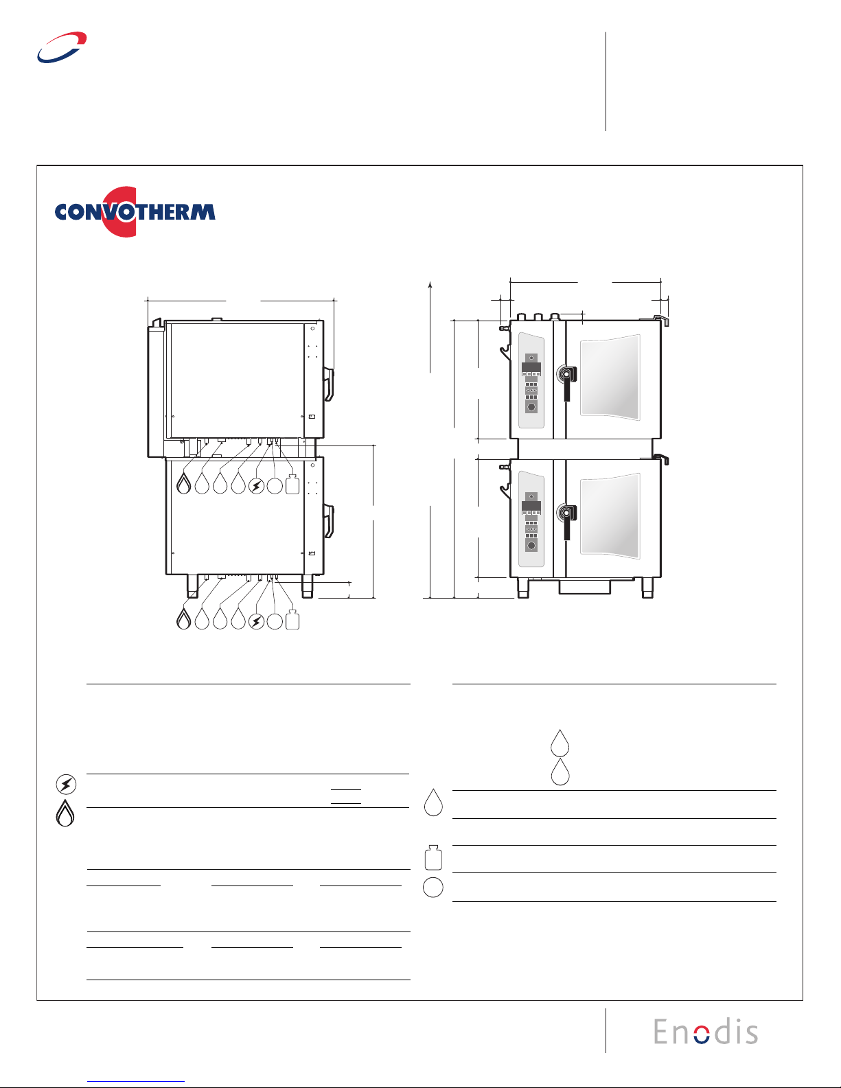
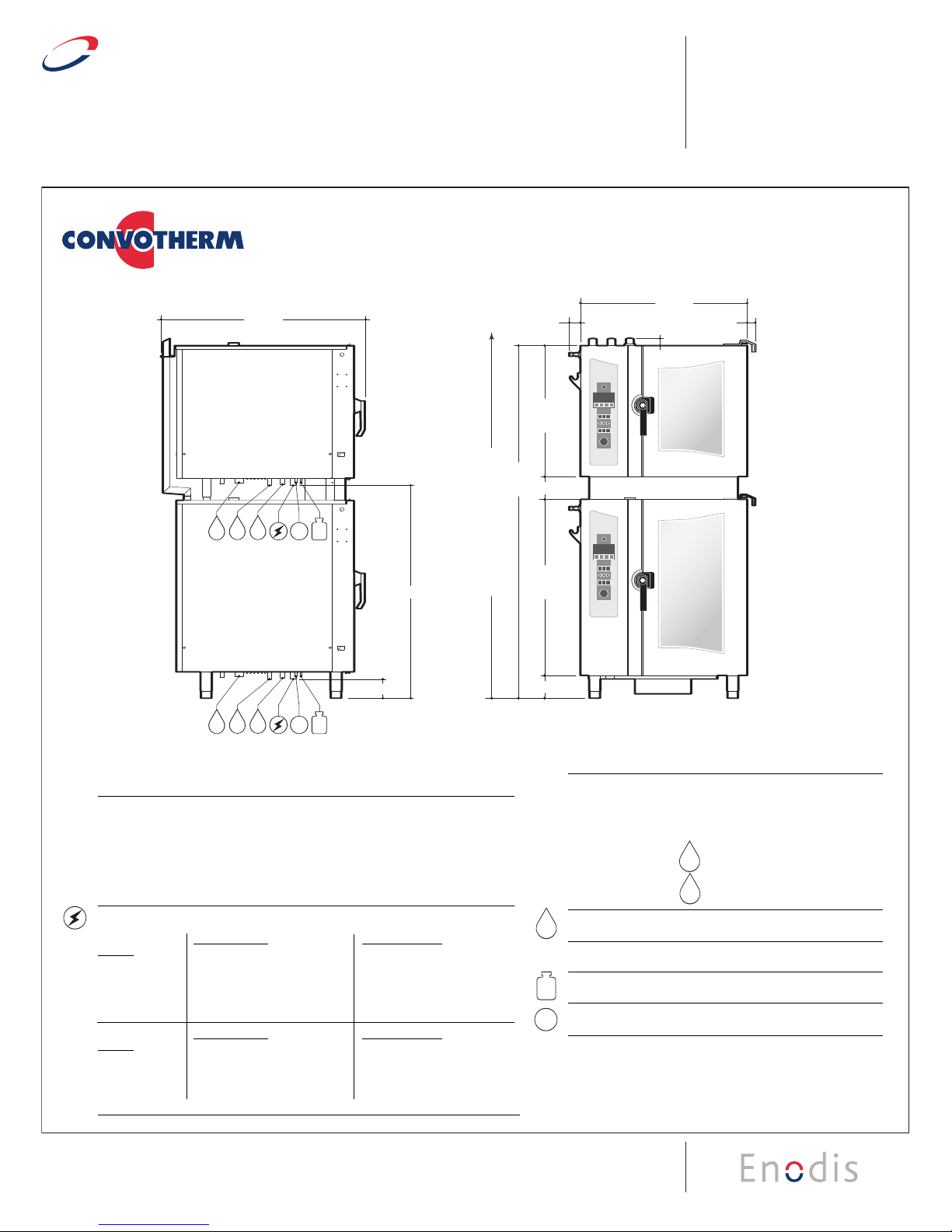
COMBI OVEN-STEAMER
Stacking Kits for Electric Table Type Models
(OEB 6.20 on OEB 10.20 or OES 6.20 on OES 10.20)
SECT. IIB PAGE 5H
0707
Model # Description
CSTK-1020 for mounting one 6.20 model on top of one 10.20 model
CSTK-1020CA for mounting one 6.20 model on top of one 10.20 model (with casters)
UNIT A
UNIT B
& CSTK-6.1CA*
36.70"
1.58"
28.43
5.00"
1.82"
67.8 5 "
71.24"
80.09"
78.41"
28.43
6.00"
6.10
6.10
2.52"
36.70"
2.52" 1.58" 1.82"
28.43
5.00"
38.98"
6.00"
6.10
10.10
47.92"
2.52" 1.58" 1.82"
CSTK-10.10 & CSTK-10.10CA*
30.12"
5.00"
38.98"
6.00"
NOTE: Overall height of unit does not change for units with casters.
78.00”(MIN. HOOD REQUIREMENT)
80.00”(MIN. HOOD REQUIREMENT)
78.00”(MIN. HOOD REQUIREMENT)
81.00”(MIN. HOOD REQUIREMENT)
RC CS
W1 W2
D
G
RC CS
W1 W2
D
RC CS
W1 W2
D
RC CS
W1 W2
D
G
4.38"
39.50"
4.38"
48.32"
47.72"
46.34"
NOTE: Overall height of unit does not change for units with casters.
UNIT A UNIT A
UNIT B
UNIT B
UNIT A UNIT A
UNIT B UNIT B
LEFT SIDE VIEW
FRONT VIEW
LEFT SIDE VIEW
FRONT VIEW
71.20"
47.92"
2.52" 1.58" 1.82"
30.12"
5.00"
30.12"
6.00"
78.00”(MIN. HOOD REQUIREMENT)
RC CS
W1 W2
D
RCCS
W1 W2
D
4.38"
39.50"
46.34"
NOTE: Overall height of unit does not change for units with casters.
UNIT A UNIT A
UNIT B UNIT B
LEFT SIDE VIEW
FRONT VIEW
6.20
on 6.20
GAS
6.20
on 6.20
ELEC
6.20
on 10.20
GAS
6.20
on 10.20
ELEC
80.09"
47.92"
2.52" 1.58" 1.82"
30.12"
5.00"
38.98"
6.00"
81.00”(MIN. HOOD REQUIREMENT)
RC CS
W1 W2
D
G
RC CS
W1 W2
D
G
4.38"
48.32"
47.72"
NOTE: Overall height of unit does not change for units with casters.
UNIT A UNIT A
UNIT B UNIT B
LEFT SIDE VIEW
FRONT VIEW
NOTE: Overall height of unit does not change for units with casters.
RC CS
W1 W2
D
G
RC CS
W1 W2
D
G
4.38"
38.08"
39.21"
LEFT SIDE VIEW
6.10
on 6.10
GAS
6.10
on 10.10
GAS
RC CS
W1 W2
D
G
RC CS
W1 W2
D
G
4.38"
48.54”
39.21"
NOTE: Overall height of unit does not change for units with casters.
UNIT A
UNIT B
LEFT SIDE VIEW
UNIT A
UNIT B
37.83"
LEFT SIDE VIEW
36.70"
1.58" 1.82"
2.52"
RC CS
W1 W2
D
RC CS
W1 W2
D
NOTE: Overall height of unit does not change for units with casters.
4.38"
38.08"
28.43
5.00"
67.8 5 "
28.43
6.00"
78.00”(MIN. HOOD REQUIREMENT)
UNIT A
UNIT B
UNIT A
UNIT B
RC CS
W1 W2
D
RC CS
W1 W2
D
37.83"
NOTE: Overall height of unit does not change for units with casters.
LEFT SIDE VIEW
UNIT A
UNIT B
4.38"
48.54"
6.10
on 6.10
ELEC
6.10
on 10.10
ELEC
36.70"
1.58"
28.43
5.00"
1.82"
67.8 5 "
28.43
6.00"
78.00”(MIN. HOOD REQUIREMENT)
2.52"
78.41"
36.70"
1.58" 1.82"
28.43
5.00"
38.98"
6.00"
80.00”(MIN. HOOD REQUIREMENT)
2.52"
78.41"
36.70"
1.58" 1.82"
28.43
5.00"
38.98"
6.00"
80.00”(MIN. HOOD REQUIREMENT)
2.52"
UTILITIES (Utility connection shown below are listed per unit)
Required Clearances:
Rear - 2", Left Side - 4", Right Side - 2 1/2"
• Allow for sufficient distance if a "high heat source" (i.e. Broiler) is located next to
the unit.
• Allow for sufficient clearance on left side for service access (contact the factory
service department for recommendations).
• Installation must comply with all local fire and health codes.
Electrical Requirements:
Do not connect to a G.F.I. outlet.
BOILER UNIT A -OEB-6.20 UNIT B -OEB-10.20
MODELS
208/3/60 240/3/60 440/3/60 480/3/60 208/3/60 240/3/60 440/3/60 480/3/60
Total Connected Load: 16.4 KW 21.6 KW 18.5 KW 22 KW 26.3 KW 34.9 KW 29.4 KW 34.9 KW
Hot Air: 14.7 KW 19.6 KW 16.5 KW 19.6 KW 25.8 KW 34.3 KW 28.8 KW 34.3 KW
Steam Generator: 12.8 KW 17.1 KW 14.3 KW 17.1 KW 20.5 KW 27.3 KW 22.9 KW 27.3 KW
Amps per Phase: 45.5 51.8 24.2 26.4 77.8 88.8 41.4 44.9
BOILERLESS UNIT A -OES-6.20 UNIT B -OES-10.20
MODELS
208/3/60 240/3/60 440/3/60 480/3/60 208/3/60 240/3/60 440/3/60 480/3/60
Total Connected Load: 16.4 KW 21.6 KW 18.5 KW 22 KW 26.3 KW 34.9 KW 29.4 KW 34.9 KW
Hot Air: 14.7 KW 19.6 KW 16.5 KW 19.6 KW 25.8 KW 34.3 KW 28.8 KW 34.3 KW
Amps per Phase: 45.5 51.8 24.2 26.4 77.8 88.8 41.4 44.9
Water Connections: Cold Water (drinking water quality)
Flow Pressure: 30 - 60 PSI
Water Inlets: 3/4" GHT-F (Female Garden Hose
Connection)
Treated Water for Steam Generator
Untreated Water for Condenser
Drain Connection: 2" Tube
Venting: Exhaust Hood required
*Connection for Cleaning Solution
*Connection for Rinse Cycle
*Available as an option
Note: For additional connection details,
see spec sheet for each individual
combi model to be stacked.