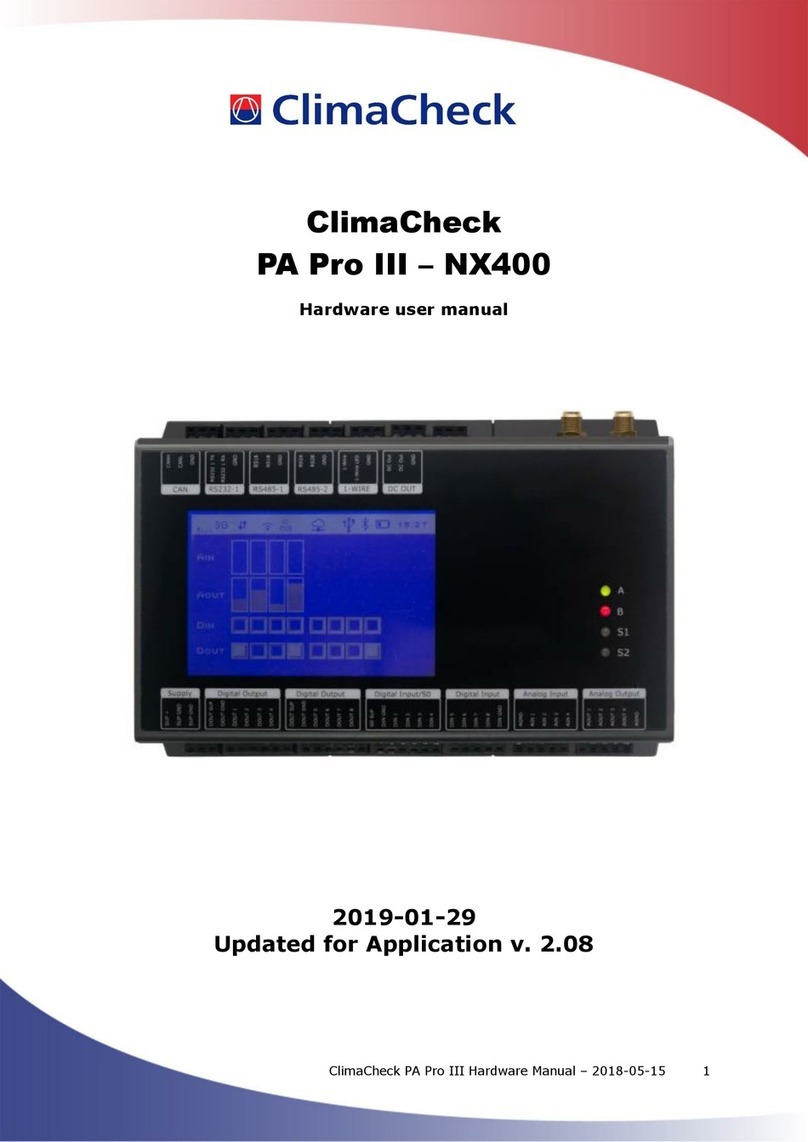
ClimaCheck PA Pro III online User manual

Installation Manual PA Pro III online –2018-03-16 Page 2 of 30
Safety Precautions
Read the instruction manuals for all relevant equipment carefully before
starting to use ClimaCheck Performance Analysing systems.
ClimaCheck PA Pro III is a measuring and analysing system developed to give
detailed evaluation of refrigeration, air-conditioning and heat-pump systems in
development laboratories, production tests and in the field.
If equipment is used in a way not specified by producer the protection and safety provided may be
impaired.
Certifications/licenses are required in most countries for activities related to electrical systems,
pressurised systems and systems charged with refrigerants that have environmental impacts
and/or flammability.
ClimaCheck products are only intended for use by competent technicians/engineers complying with
local requirements for certifications/licenses.
Any work with electricity, pressurised systems or refrigerant involves potential dangers to human
health and system integrity if not conducted with caution. Always inspect the equipment for
damaged cables or other components before use. For many installations loss of product or
disturbances in operation incurs high costs. ClimaCheck assumes no responsibility for injuries or
costs that may occur as a result of failures in connection with measurements. The user must
evaluate whether an inspection can be carried out without risk of injury and/or damage.
Measurements should only be carried out when it can be done under safe working conditions and
without risks.

Installation Manual PA Pro III online –2018-03-16 Page 3 of 30
Table of Contents
Safety Precautions............................................................................................................... 2
1Introduction .................................................................................................................. 5
2Handling and safety ....................................................................................................... 6
3Required documents and equipment ................................................................................ 7
4Connection of power measurement .................................................................................. 8
4.1 Motor configurations ................................................................................................. 8
4.1.1 Part Winding ..................................................................................................... 8
4.1.2 Y/D (Star/Delta) ................................................................................................ 8
4.2 Systems with inverter ............................................................................................... 9
4.3 Differential protection ............................................................................................... 9
5Connection of sensors ...................................................................................................10
5.1 Mounting of pressure transmitters/transducers ...........................................................10
5.2 Mounting temperature sensors ..................................................................................10
5.2.1 Required insulation ...........................................................................................10
5.2.2 Compensating for changes in temperature sensor cable length ...............................11
5.3 1-wire temperature sensors......................................................................................11
6ClimaCheck PA Pro III Hardware.....................................................................................13
6.1 LED indicators.........................................................................................................13
6.2 Display...................................................................................................................14
6.3 Start......................................................................................................................15
6.4 Menus....................................................................................................................16
6.5 Monitor ..................................................................................................................16
6.5.1 View all values .................................................................................................17
6.5.2 Send interval / Intense send ..............................................................................17
6.5.3 Signal level ......................................................................................................17
6.6 Setup.....................................................................................................................17
6.6.1 Reload configuration .........................................................................................17
6.6.2 Reboot ............................................................................................................18
7Configuration of 1-wire sensors ......................................................................................19
7.1 Connecting sensors..................................................................................................19
7.2 Replace a 1-wire senor.............................................................................................19
7.3 Clear all 1-wire sensors ............................................................................................19
8Configuration of PA Pro III .............................................................................................21
8.1 Change analog input mode (mA/V) ............................................................................21
8.2 Change communication mode ...................................................................................21
9Configuration of Power Meter EM24.................................................................................23
9.1 Change CT-ratio configuration...................................................................................23
9.2 Change Modbus address...........................................................................................23
10 Configuration of Power Meter EM210 ...............................................................................24
10.1 Change CT type configuration ...................................................................................24
10.2 Change Modbus address...........................................................................................24
11 Configuration of IO module R560 ....................................................................................25
11.1 Change Modbus address...........................................................................................25
11.2 Change Analog input mode .......................................................................................25
12 Troubleshooting............................................................................................................26
12.1 Pressure readings....................................................................................................26
12.1.1 Required tools and spare parts ...........................................................................26
12.1.2 Transmitter type...............................................................................................26
12.1.3 Supply voltage .................................................................................................26
12.1.4 Pressure signal .................................................................................................27
12.2 Temperature readings with PT1000 sensors ................................................................27
12.2.1 Required tools and spare parts ...........................................................................27
12.2.2 Common issues ................................................................................................28
12.2.3 Temperature-resistance table.............................................................................28

Installation Manual PA Pro III online –2018-03-16 Page 4 of 30
12.3 Temperature readings with 1-wire sensors .................................................................28
12.4 Power measurement ................................................................................................29
12.4.1 Supply voltage .................................................................................................29
12.4.2 Communication ................................................................................................29
12.4.3 Measurement ...................................................................................................29
Note: Areas with red side marking are related to certification and should not be changed without
new date here log on changes are kept separately. Current date of changes is 2018-03-16.

Installation Manual PA Pro III online –2018-03-16 Page 5 of 30
1Introduction
ClimaCheck1is a measuring and analysing system developed to give detailed evaluation of
refrigeration, air-conditioning and heat-pump systems in development laboratories, production
tests and in the field.
The method is based on measurements in the refrigeration circuit and does not require any fixed
installation of metering equipment in the system. The advantages of easy connection, immediate
and detailed information makes the ClimaCheck method superior for evaluating all refrigeration,
air-conditioning and heat pump systems.
An increased focus on energy efficiency can be seen in the EU Directive 2002/91/Ec on
the Energy Performance of Building and several other requirements on energy
performance on other markets. This directive requires annual inspections with
verifications of energy efficiency of all AC systems with more that 12 kW rated capacity.
Measuring with ClimaCheck gives and excellent foundation for performance inspections.
The ClimaCheck Performance Analysing method allows complete analysis of energy performance
as well as presenting all information to validate the individual components and their optimization
without the requirement of any fixed equipment making it possible to immediately identify and
locate any deficiencies in the system. The method was patented in 1986 and has since been used
in Sweden and internationally in the Product ETM 1500, ETM 2000, ClimaCheck PA 8:7 and now
ClimaCheck PA Pro.
The server based monitoring software is constantly logging the performance of the system and
uses the globally accepted equations for refrigerant properties in RefProp established by NIST
(National Institute of Standards and Technologies in USA). Anyone with the user name and
password can log in to the system from an Internet connected PC as well as have the server send
alarms when important parameters fall outside of their specified ranges.
The ClimaCheck method is suitable for almost all compressor-based refrigeration processes. All
suction or discharge gas cooled hermetic and semi hermetic compressors can be fully evaluated
without any compressor or system specific information. For open compressors the electrical motor
efficiency is given as input and for compressors with external cooling of air, water, oil or liquid
injection information on the cooling need to be entered to give a full capacity and COP accuracy.
For many types of systems data on compressor cooling are well known and necessary parameters
are known. ClimaCheck Specialists should be consulted to give advice on non-standard systems.

Installation Manual PA Pro III online –2018-03-16 Page 6 of 30
2Handling and safety
To ensure safe installation and operation the following instructions must be followed carefully:
-The equipment should be powered by either 90 –264 V AC at 47 –64 Hz or 120 –370 V
DC. The maximum power consumption of the system is 25 W.
-An easily reachable external switch for breaking power to the installation has to be
available.
-Operating temperature range for the equipment is -20 to +50 °C.
-Operating humidity is R.H. 0 –90 % non-condensing.
-Maximum operating altitude: 2000 m
-The equipment is designed for a maximum of Pollution Degree 2.
-The equipment enclosures have not been tested for UV-resistance and are thus not
approved for outdoor use.
-The enclosure must be mounted with at least three sides having a minimum clearance of
10 cm. The front must have a clearance of at least 30 cm.
-Burned out fuses must be replaced in accordance to the table below. Use only UL/CSA
approved fuses.
Marking on
fuse holder
Fuse type
L
T 1 A L, 250 V
L1
T 500 mA L, 250 V
L2
T 500 mA L, 250 V
L3
T 500 mA L, 250 V
-See section 4 for important safety instructions when connecting the power measurement.
-For all electrical wires not included with the equipment, use UL1569 AWG20 or better. Not
that special considerations should be taken for the wiring of the power meters, see section
4.
-The standard enclosure is marked with protection class IP55, but the protection of the final
installation may be lower depending on several factors. ClimaCheck do not guarantee a
certain protection class.
-If the instructions in this section and the rest of the manual are not observed, the
protection provided by the equipment may be impaired.

Installation Manual PA Pro III online –2018-03-16 Page 7 of 30
3Required documents and equipment
In addition to this instruction a number of documents and equipment is required in order to
successfully complete the installation:
-Flow chart of the system with sensor placement, supplied with the attached configuration
document.
-Wiring diagram of the system, supplied with the attached configuration document.
-Small flathead screwdriver 2.5 x 0.5 mm.
-Aluminium tape.
-Insulation tape.
-A number of standard tools depending on the nature of the installation.

Installation Manual PA Pro III online –2018-03-16 Page 8 of 30
4Connection of power measurement
Important!
Improper use of ClimaCheck power meters may cause high voltage
build up that can be dangerous both for equipment and operators. Adhere to the
practices below to avoid this:
-Always connect the CTs to the power meter before they are attached around a live
wire.
-Always remove the CTs from the live wire before the cables to the power meter
are disconnected.
-Incorrect connection of voltage between phase and neutral will damage the
equipment.
-Never use the CTs on uninsulated wires or rails.
In addition, follow the steps below to assure proper power and energy readings:
-It is important to only measure the power to the compressor. Make sure the measurement
is done after the point where circulation pumps and fans are connected.
-Make sure that the voltage and current for each phase corresponds with the markings on
the measuring equipment and that the arrow on the current clamps are pointing in the
direction of the current.
-Make sure that the CTs are completely closed and that the contact areas are clean.
-Check that the connections are correct by reading the voltage, current and power on the
display of the power meter. If you find a problem remove the clamps and attach L1
followed by a control and the repeat the process for L2 and L3.
4.1 Motor configurations
Power measurements require good understanding of the electrical layout of the plant.
It is for example necessary to identify if a three-phase motor is part winding or Y/D (Star/Delta)
and connect accordingly.
4.1.1 Part Winding
Part winding means that the motor has two separate windings and the total current to these should
be measured. This can be done in several ways depending on the physical restrictions of cables and
CTs.
-Preferred choice is to measure before the contactors where the total current runs through
one lead. This can sometimes be physically impossible.
-One alternative is to put clamps around both L1 cables after the contactor or in the
connection box on the compressor if this can be done. This is repeated for L2 and L3.
-It is possible to measure with 6 clamps i.e. 2 in parallel to the instrument per phase.
-If there is no way to connect around the total current an acceptable approximation can be
achieved by measuring on one of the contactors (the one with largest power draw is
preferred) and adjusting the power scale in the ClimaCheck software Input tab. The ratios
are typically 50/50 or 60/40 and can be deduced by moving the clamp back and forth.
4.1.2 Y/D (Star/Delta)
Motor with Y/D start should preferably be measured before supply is split between the three
contactors this normally consist of e.g. at L1, L2 and L3.

Installation Manual PA Pro III online –2018-03-16 Page 9 of 30
If measured after the split to K1 and K2/K3 both leads should be measured.
After the “Run” contactor K3 and the split to “Start” contactor K2 the cables to the motor will be
connected to different phases depending on position of K2 and K3.
If measured at motor correct cables must be matched so total L1, L2 respectively L3 feed is
measured but the reading will be incorrect during start when K2 is activated.
In picture below:
L1 is feeding U and Z
L2 is feeding V and X
L3 is feeding W and Y
If designation of poles is unknown the pairs can be identified by measuring voltage between poles
matching pairs will show zero voltage difference.
Figure 1 - Y/D (Star/Delta)
4.2 Systems with inverter
If inverters are used it is normally necessary to measure before inverter and use a loss factor of
typically 3-6% to compensate for the heat loss. Ensure that i.e. fans do not consume power from
the same feed. If so an offset can be added in the input tab
4.3 Differential protection
Differential protection is used to improve the security of the installation and will cut the supply if
any current is drawn outside the “protected loop”. As the EM210 is powered by the voltage line L1
and L2, differential protection must be taken into account when connecting.
Start contactor
Run contactor

Installation Manual PA Pro III online –2018-03-16 Page 10 of 30
5Connection of sensors
Sensors should be placed in accordance with the supplied flowchart and connected to the system
as shown on the supplied wiring diagram. All sensors should be checked against room temperature
and atmosphere pressure before being attached. Check section 12 for troubleshooting.
5.1 Mounting of pressure transmitters/transducers
Pressure should be registered as close as possible to the compressor inlet and outlet. Pressure drop
between sensor and compressor will affect the accuracy.
5.2 Mounting temperature sensors
Temperature sensors may be mounted on the outside of piping with the ClimaCheck method due to
the inherent low sensitivity to temperature errors. This is a critical advantage compared to
traditional methods but should not be taken as an excuse to not follow the recommended
procedures below.
Temperature sensors should be mounted:
-10-20 cm from the compressor, flanges, valves or other objects that can act change the
surface temperature compared to the inner temperature of the tube.
-Maximum contact should be ensured by:
▪Removal of any insulation and paint on the tube.
▪When mounted in pockets the sensor must be securely pressed against the wall of
the pocket.
▪Heat transfer paste should always be used for surface and “pocket” mounted
sensors.
-Aluminium tape should always be used for surface mounting.
-Insulation should be carefully done and diffusion tight if the surface/object is cold. The
openings of dip tubes/pockets should be sealed/covered with insulation.
-In the case of PT1000 sensors with red four lead cables, the pairs with the same colour
should be attached together to the terminals.
Figure 2 - Apply sensors with heat transfer compound, Aluminium and insulation
5.2.1 Required insulation
Many factors have an impact on required insulation to achieve good accuracy:
-dT to ambient
High dT obviously increases the error from poor insulation.
-Radiation from surrounding hot/cold surfaces.

Installation Manual PA Pro III online –2018-03-16 Page 11 of 30
-Material type in tube
Good heat transfer decreases the error caused by the wall from best to worse copper - iron
- stainless –plastic.
-Material thickness in tube
Dimension, pressure and material define thickness thicker tube wall increase need of
insulation.
-Condensation
It is important to avoid condensation on or near sensor as this will have a significant impact
on temperature reading.
-Ice formation
If ice is allowed to form around sensors (condensation on cold tubes) this creates an
insulation.
Importance of accuracy
A service check can allow a higher tolerance for errors than an inspection to validate that
performance is according to contract.
Note that even if temperatures on secondary side do not have any impact on capacity and COP of
refrigeration process, they will, if nominal data is taken from manufacturers, strongly impact these
reference data.
We advise common sense to be applied, with special attention to discharge and suction line sensor
on the refrigerant side due to high dT and risk of condensation.
For best accuracy, remove dirt, paint and corrosion, and avoid pushing sensors inside existing
insulation - cut a hole in insulation instead. Always use heat transfer paste and aluminium tape to
make insulation on cold tubes so that condensation or ice formation cannot take place on sensor.
Smaller size copper tube minimum 60 mm x 8 mm tight insulation pressed against
tube (thickness 8 mm or 3 turns of insulation tape)
Larger size CU (> 35 mm/1.5") minimum 100 mm x 8 mm tight insulation pressed against
tube (thickness 8 mm or 3 turns of insulation tape)
Steel/plastic/stainless piping minimum 15 cm x 8 mm insulation
5.2.2 Compensating for changes in temperature sensor cable length
No configuration has to be made when using black 1-wire sensors and when using the entire white
5 m cable or the entire red 10 m cable of a PT1000 temperature sensor. If a PT1000 cable is
shortened or lengthened the change in resistance needs to be compensated for. The standard
temperature offset (0.35 K) needs to be increased for a longer cable or decreased for a
shorter cable. The white cable got a resistance of 0.07 K/m and the red cable 0.035 K/m (using
all four leads in pairs).
Fill in the offset for each changed PT1000 in the Configuration document and send to ClimaCheck
support.
5.3 1-wire temperature sensors
1-Wire temperature sensors are bus sensors and the measured values are not affected by the
resistance in the cable between the master (PA Pro III) and the slave (sensor). However, there are
some limitations on how to wire these sensors. The preferred topology can be seen in Figure 3.

Installation Manual PA Pro III online –2018-03-16 Page 12 of 30
ClimaCheck
1-wire master
concom
PA Pro III
Split
(+0.5m)
Split
(+0.5m)
< X m
1-wire sensor
(+0.5 m)
1-wire sensor
(+0.5 m)
1-wire sensor
(+0.5 m)
< 3 m
<3 m
< 3 m
< X m
1-wire sensor
(+0.5 m)
1-wire sensor
(+0.5 m)
< 3 m
< 3 m
Split
(+0.5m)
1-wire sensor
(+0.5 m)
1-wire sensor
(+0.5 m)
1-wire sensor
(+0.5 m)
< 3 m
<3 m
< 3 m
< X m Split
(+0.5m)
1-wire sensor
(+0.5 m)
1-wire sensor
(+0.5 m)
1-wire sensor
(+0.5 m)
< 3 m
<3 m
< 3 m
< X m
1-wire bus
Stub
i.e. cold room,
Heating system,
chilled water
i.e. missing unit
temperatures
Figure 3 - 1-wire preferred topology
The PA Pro is connected at one end of the 1-wire bus and each sensor is connected to the bus with
branches or “stubs” where each stub is less than 3m. The PA Pro can handle a total of 16 sensors
and a total “weight” of 65 m. The weight is the length of all cables + 0.5m per sensor + 0.5m per
split.
Weight = total cable length + 0.5*sensor + 0.5*split
Example: 3 sensors on 2 meter stubs that is located 5 meters from the PA Pro with 1 split has a total
weight of 0.5*3+(2*3+5)+0.5*1=14.
Do not run signal wires in parallel with power cables.
Check section 7 for configuration of 1-wire sensors.

Installation Manual PA Pro III online –2018-03-16 Page 13 of 30
6ClimaCheck PA Pro III Hardware
This section describes the details of the ClimaCheck PA Pro III hardware.
6.1 LED indicators
The ClimaCheck PA Pro III has 4 LED indicators:
-A: ClimaCheck online
-B: 1-wire / Modbus
-S1: Status
-S2: Modem
The A LED indicates the status on contact with ClimaCheck online server.
-A Led (CC Online)
-Status
900ms on,
900ms off
Connection with ClimaCheck Online OK (Normal operation with internet
connection)
Off
No connection with ClimaCheck Online (Normal operation without
internet connection)
Fast blinking
Unsuccessful to send data to ClimaCheck Online
The B LED indicates the status of 1-wire and Modbus communication.
-B LED (1W/Modbus)
-Status
900ms on,
900ms off
All configured Modbus and 1-wire units OK (Normal operation)
400ms on,
400ms off
Modbus communication error
Continuous on,
off
1-wire communication error
The S1 LED indicates the status on the PA Pro program.
-S1 LED (Status)
-Status
500ms on,
500ms off
PA Pro application running OK (Normal operation)
1500ms on,
500ms off
PA Pro application running OK, while charging the internal back-up
battery.
500ms on,
500ms off
PA Pro application running OK, while connected to ClimaCheck
software (Normal operation, while connected to software)
Fast blinking
The unit has been forced into recovery mode with the use of the system
switch. The application is not executing.
Fastest blinking
The unit is initializing, preparing to start the application.
75ms on,
925ms off
Execution speed is different from full-speed.
Fast blinking
A runtime error has been detected in the program, contact ClimaCheck
support
Alternating
Fast/Slow
The unit has lost its firmware, contact ClimaCheck support
The S2 LED indicates the modem status.
Communication status is showed as an icon in the display and with the S2 LED, see table below.

Installation Manual PA Pro III online –2018-03-16 Page 14 of 30
-S2 LED (Modem)
-Status
Off
The GSM module is turned off.
600ms on,
600ms off
No SIM card inserted or no PIN code entered, or network search in
progress, or ongoing user authentication, or network logon in progress.
Single 75ms on,
3s off
Logged to the network, no call in progress.
Double 75ms on
3s Off
A GPRS session is active. Bars indicate signal strength
Flashing
Indicates GPRS data transfer.
6.2 Display
On the front of the PA Pro III unit a 240x160 pixel, withe on blue, LCD display with built in resistive
touch sensing can be found.
The top part of the display is reserved for a status bar showing status of the different communication
interfaces as well as the time and the battery status, see Figure 4.
The main part of the display is reserved for internal ClimaCheck PA Pro III application showing menus
and data. The lower and right side is used for virtual buttons to navigate.
Figure 4 - Display with status bar and virtual buttons
The table below describes the icons on the status bar.
-
-Icon
-Status
-GSM Status
GSM off
GSM on
Signal strength
GSM network type
2G
3G
Mobile network status
Network connected

Installation Manual PA Pro III online –2018-03-16 Page 15 of 30
Roaming
Network connected while roaming
Call Status
Call active (not used in Climacheck application)
Wi-Fi Status
Wi-Fi Off
Wi-Fi on
Wi-Fi signal level
LAN Status
LAN off
LAN on (disconnected)
LAN connected
RTCU Gateway Status
RTCU Gateway not enabled
RTCU Gateway enabled
RTCU Gateway connected
USB status
USB host supported
Bluetooth status
Bluetooth off
Bluetooth on
Power status
Battery level (animated while charging)
6.3 Start
ClimaCheck PA Pro III starts directly when it is connected to the power supply. After half a minute,
the display shows Connect to GPRS? (Default is Yes) or Connect to LAN? (Default is Yes)
depending on the configuration whether to use a SIM card or local network.
Press on Yes or wait for 10 seconds, to be able to connect to the internet and send data to
ClimaCheck online.
After around half a minute, the display shows ClimaCheck PA Pro III, the 6 digit ID, and the
application version. The unit can now be used.
The unit can be turned off by disconnecting the power. The internal backup battery allows for a
safe shut down.

Installation Manual PA Pro III online –2018-03-16 Page 16 of 30
6.4 Menus
There are 8 push buttons on the PA Pro touch screen. To open the main menu, press Esc. To open
a sub menu, press SEL.To choose a function or confirm a configuration, press OK. To go back,
press ESC. The menu structure is shown in Figure 5.
Figure 5 - Menu structure
6.5 Monitor
All values from sensors and power meters can be seen under the Monitor menu. From the Monitor
menu, the send interval to ClimaCheck online can also, temporarily, be changed.

Installation Manual PA Pro III online –2018-03-16 Page 17 of 30
6.5.1 View all values
To view all values:
-Press ESC to enter the Main menu
-Press Down until “Monitor” is shown in the display
-Press SEL to enter Monitor menu
-“Show values” appears in the display
-Press OK
Values are shown with a sensor/value number, a comment/description, the sensor reading, and a
unit. Press Up/Down to step through the list of values.
6.5.2 Send interval / Intense send
Data is sent to the ClimaCheck online server once every minute when the compressor is on and every
5 minutes when the compressor is off. To activate “intense send” and send data every 15 seconds:
-Press ESC to enter the Main menu
-Press Down until “Monitor” is shown in the display
-Press SEL to enter Monitor menu
-Press down until “Intense send” is shown in the display
-Press OK
-“Intense Send Active” appears
Intense send is automatically swished off after 15 minutes.
6.5.3 Signal level
When using the PA Pro III with GRPS modem or wireless WLAN, it is possible to check the signal
level.
-Press ESC to enter the Main menu
-Press Down until “Monitor” is shown in the display
-Press SEL to enter Monitor menu
-Press down until “Signal Level” is shown in the display
-Press OK
6.6 Setup
All configuration of the ClimaCheck PA Pro III unit, except 1-wire sensors and network configuration,
can be done on the ClimaCheck Online server. Any changes to Modbus addresses or external units
such as energy meters or IO modules can be done on the ClimaCheck Online server and then
downloaded to the unit. If the unit has an internet connection it will try to contact the server every
6 hours to check for commands to Reload configuration from the server or to Restart.
To set up 1-wire sensors, check section 7.
6.6.1 Reload configuration
It is possible to force a reload of the configuration through the hardware.
Make sure the unit has internet connection and then
-Press ESC to enter the Main menu
-Press Down until “Setup” is showed in the display
-Press SEL to enter setup menu
-Press Down until “Get Config Online” is showed in the display
-Press OK to load configuration from CC Online server
-“Waite for config, Loading..” appears in the display
After a few seconds, when the configuration has been updated, the unit will go back to the initial
view.

Installation Manual PA Pro III online –2018-03-16 Page 18 of 30
6.6.2 Reboot
It is possible to force a reboot of the unit through the hardware:
-Press ESC to enter the Main menu
-Press Down until “Setup” is showed in the display
-Press SEL to enter setup menu
-Press Down until “Restart/Reboot” is showed in the display
-Press OK
The unit will reboot.

Installation Manual PA Pro III online –2018-03-16 Page 19 of 30
7Configuration of 1-wire sensors
Each 1-wire sensor has a unique ID to identify it on the 1-wire bus and each sensor needs to be
configured/connected in the PA Pro.
The provided 1-wire sensors are already configured and labelled. To add or replace a non-
configured 1-wire sensor, follow the sections below.
Check section 12.3, for troubleshooting.
7.1 Connecting sensors
The sensors need to be connected and configured one at a time. Use the following sequence to
setup and connect the sensors:
-Press ESC to enter the Main menu
-Press Down until “Setup” is shown in the display
-Press SEL to enter setup menu
-“1W Sensor Setup”appears in the display
-Press OK to start setup
If this is the first setup, “T1 Sensor not conf” appears in the display. If sensors are already
configured, they will be listed.
-With the up and down arrows go to the position you want to save a sensor to
-Press SEL
-“TX NEW=xxxxxx OK” is shown in the display, where TX is the position and xxxxxx is the ID
number of the sensor
-Confirm with OK, “S-RID Saved” appears for 2 seconds
-Temperature reading and ID appears in the display “TX=XX.X ID=xxxxxx”
-Press up/down to continue with the next sensor or ESC 4 times to go back to the main menu.
If “No new s-r found” appears while setting up a new sensor, the PA Pro cannot find any sensor on
the bus that is not already configured. Check the connection and make sure the sensor has not
been configured already.
7.2 Replace a 1-wire senor
To replace a 1-wire sensor:
-Disconnect old sensor
-Press ESC to enter the Main menu
-Press Down until “Setup” is shown in the display
-Press SEL to enter setup menu
-“1W Sensor Setup”appears in the display
-Press OK
-Select the sensor number in the list, it will say “Sensor missing”.
-Connect new sensor and press SEL,
-“Tx NEW=xxxxxx OK” is shown in the display
-Confirm with OK, “S-RID Saved” appears for 2 seconds
-Temperature reading and ID appears in the display “TX=XX.X ID=xxxxxx”
-Press ESC 4 times to go back to the main menu.
7.3 Clear all 1-wire sensors
To clear all configured 1-wire sensors:
-Press ESC to enter the Main menu
-Press Down until “Setup” is shown in the display
-Press SEL to enter setup menu
-Press down until “Clear 1W Sensors” is shown in the display
-Press OK
Table of contents
Other ClimaCheck Measuring Instrument manuals
Popular Measuring Instrument manuals by other brands

Automation Dr. Nix
Automation Dr. Nix QNix 7500 instruction manual

Siemens
Siemens FIDAMAT 6 operating instructions

Endress+Hauser
Endress+Hauser Levelflex M FMP40 Description of Device Functions

Hioki
Hioki MR8880-20 quick start guide

janitza
janitza UMG 96 operating instructions

LI-COR
LI-COR LI-8100A manual